Makita RT0700C User manual

1
GB Trimmer INSTRUCTION MANUAL
SI Rezkalnik NAVODILO ZA UPORABO
AL Makina buzëprerëse MANUALI I PËRDORIMIT
BG Нагер
РЪКОВОДСТВО ЗА ЕКСПЛОАТАЦИЯ
HR Škare PRIRUČNIK S UPUTAMA
MK Тример
У
ПАТСТВО ЗА УПОТРЕБА
RO Maşinăde frezat unimanualăMANUAL DE INSTRUCŢIUNI
RS Уређај за опсецање
У
ПУТСТВО ЗА УПОТРЕБУ
RUS Триммер
РУКОВОДСТВО ПО ЭКСПЛУАТАЦИИ
UA Фрезер ІНСТРУКЦІЯ ЗЕКСПЛУАТАЦІЇ
RT0700C

2
1
2
3
45
6
1 011834
1
23
2 011836
1
3 011835
1
2
3
4 011837
1
2
3
5 011987
1
23
4
6 001985
7 011838
1
2
3
2
8 011839
1
2
3
45
6
10mm (3/8")
7
9 011982
10 011840
1
2
3
4
11 001990
1
2
34
12 011841
A
13 011842
1
2
3
4
5
14 001993
1
2
3
4
5
15 001994

3
1
2
3
16 011843 17 011844
1
2
3
4
18 011845
1
2
3
19 001998
1
20 011993
1
2
21 011994
22 012085
1
2
3
23 011858
1
23
24 011985
1
2
25 011859 26 011860
1
2
27 011861

4
1
2
28 011862
1
2
3
29 011992
1
2
3
30 011934
1
2
3
4
31 011935
1
2
3
32 011984 33 011986
1
2
34 011855
1
2
35 011856
1
36 011857

5
1
2
3
4
5
6
78
37 011983
1
23
4
38 001985 39 011848
123
40 011849
A
41 011850 42 011851
12
3
43 011852
1
2
3
45
6
7
44 003695 45 011854
1
46 001145
1
2
47 011846 48 005116

6
R
49 005117 50 005118 51 005120
52 005121 53 005125 54 005126
55 005129 56 005130 57 005131
58 005132 59 005133 60 005134
61 005135

7
ENGLISH (Original instructions)
Explanation of general view
1-1. Bit protrusion
1-2. Tool base
1-3. Scale
1-4. Locking lever
1-5. Adjusting screw
1-6. Hex nut
2-1. Switch
2-2. OFF (O) side
2-3. ON ( I ) side
3-1. Speed adjusting dial
4-1. Tighten
4-2. Loosen
4-3. Hold
5-1. Tighten
5-2. Loosen
5-3. Shaft lock
6-1. Feed direction
6-2. Bit revolving direction
6-3. Workpiece
6-4. Straight guide
8-1. Base protector
8-2. Screws
8-3. Screwdriver
9-1. Straight bit
9-2. Base
9-3. Templet
9-4. Distance (X)
9-5. Workpiece
9-6. Templet guide 10
9-7. Base protector
11-1. Bolt
11-2. Guide plate
11-3. Straight guide
11-4. Wing nut
12-1. Clamp screw (A)
12-2. Straight guide
12-3. Wing nut
12-4. Base
14-1. Wing nut
14-2. Guide plate
14-3. Straight guide
14-4. Center hole
14-5. Bolt
15-1. Wing nut
15-2. Guide plate
15-3. Straight guide
15-4. Center hole
15-5. Bolt
16-1. Nail
16-2. Center hole
16-3. Straight guide
18-1. Clamp screw (A)
18-2. Adjusting screw
18-3. Clamp screw (B)
18-4. Trimmer guide
19-1. Workpiece
19-2. Bit
19-3. Guide roller
20-1. Clamping screws
21-1. Base protector
21-2. Screw
23-1. Pulley
23-2. Collet nut
23-3. Collet cone
24-1. Wrench
24-2. Pulley
24-3. Shaft lock
25-1. Collet nut
25-2. Collet cone
27-1. Pulley
27-2. Belt
28-1. Locking lever
28-2. Offset base
29-1. Wrench
29-2. Hex wrench
29-3. Bit
30-1. Screws
30-2. Offset base plate
30-3. Upper section of the offset base
31-1. Bar type grip (optional accessory)
31-2. Grip attachment
(optional accessory)
31-3. Offset base plate
31-4. Trimmer base assembly
(optional accessory)
32-1. Screw
32-2. Knob type grip
32-3. Offset base plate
34-1. Plunge base
34-2. Grip
35-1. Screw
35-2. Knob
36-1. Bar type grip (optional accessory)
37-1. Adjusting knob
37-2. Lock lever
37-3. Depth pointer
37-4. Stopper pole setting nut
37-5. Fast-feed button
37-6. Stopper pole
37-7. Stopper block
37-8. Adjusting bolt
38-1. Feed direction
38-2. Bit revolving direction
38-3. Workpiece
38-4. Straight guide
40-1. Guide bar
40-2. Wing bolt
40-3. Straight guide
43-1. Screw
43-2. Base
43-3. Templet
44-1. Bit
44-2. Base
44-3. Templet
44-4. Workpiece
44-5. Distance (X)
44-6. Outside diameter of the templet
guide
44-7. Templet guide
46-1. Limit mark
47-1. Screwdriver
47-2. Brush holder cap

8
SPECIFICATIONS
Model RT0700C
Collet chuck capacity 6 mm, 8 mm, 1/4" or 3/8"
No load speed (min-1) 10,000 - 30,000
Overall length 200 mm
Net weight 1.8 kg
Safety class /II
• Due to our continuing program of research and development, the specifications herein are subject to change without notice.
• Specifications may differ from country to country.
• Weight according to EPTA-Procedure 01/2003
ENE010-1
Intended use
The tool is intended for flush trimming and profiling of
wood, plastic and similar materials.
ENF002-1
Power supply
The tool should be connected only to a power supply of the
same voltage as indicated on the nameplate, and can only
be operated on single-phase AC supply. They are double-
insulated in accordance with European Standard and can,
therefore, also be used from sockets without earth wire.
ENG905-1
Noise
The typical A-weighted noise level determined
according to EN60745:
Sound pressure level (LpA) : 82 dB (A)
Sound power level (LWA) : 93 dB (A)
Uncertainty (K) : 3 dB (A)
Wear ear protection
ENG900-1
Vibration
The vibration total value (tri-axial vector sum)
determined according to EN60745:
Work mode : rotation without load
Vibration emission (ah) : 2.5 m/s2or less
Uncertainty (K) : 1.5 m/s2
Work mode : cutting grooves in MDF
Vibration emission (ah) : 3.5 m/s2
Uncertainty (K) : 1.5 m/s2
ENG901-1
•
The declared vibration emission value has been
measured in accordance with the standard test method
and may be used for comparing one tool with another.
• The declared vibration emission value may also be
used in a preliminary assessment of exposure.
WARNING:
•
The vibration emission during actual use of the power
tool can differ from the declared emission value
depending on the ways in which the tool is used.
• Be sure to identify safety measures to protect the
operator that are based on an estimation of
exposure in the actual conditions of use (taking
account of all parts of the operating cycle such as
the times when the tool is switched off and when it
is running idle in addition to the trigger time).
ENH101-14
For European countries only
EC Declaration of Conformity
We Makita Corporation as the responsible
manufacturer declare that the following Makita
machine(s):
Designation of Machine:
Trimmer
Model No./ Type: RT0700C
are of series production and
Conforms to the following European Directives:
2006/42/EC
And are manufactured in accordance with the following
standards or standardised documents:
EN60745
The technical documentation is kept by our authorised
representative in Europe who is:
Makita International Europe Ltd.
Michigan Drive, Tongwell,
Milton Keynes, MK15 8JD, England
14.10.2010
000230
Tomoyasu Kato
Director
Makita Corporation
3-11-8, Sumiyoshi-cho,
Anjo, Aichi, JAPAN
GEA010-1
General Power Tool Safety
Warnings
WARNING Read all safety warnings and all
instructions.
Failure to follow the warnings and instructions
may result in electric shock, fire and/or serious injury.
Save all warnings and instructions for
future reference.

9
GEB019-4
TRIMMER SAFETY WARNINGS
1.
Hold power tool by insulated gripping surfaces,
because the cutter may contact its own cord.
Cutting a "live" wire may make exposed metal parts
of the power tool "live" and shock the operator.
2.
Use clamps or another practical way to secure and
support the workpiece to a stable platform.
Holding
the work by your hand or against the body leaves it
unstable and may lead to loss of control.
3. Wear hearing protection during extended
period of operation.
4. Handle the bits very carefully.
5. Check the bit carefully for cracks or damage
before operation. Replace cracked or
damaged bit immediately.
6. Avoid cutting nails. Inspect for and remove all
nails from the workpiece before operation.
7. Hold the tool firmly.
8. Keep hands away from rotating parts.
9. Make sure the bit is not contacting the
workpiece before the switch is turned on.
10. Before using the tool on an actual workpiece,
let it run for a while. Watch for vibration or
wobbling that could indicate improperly
installed bit.
11. Be careful of the bit rotating direction and the
feed direction.
12. Do not leave the tool running. Operate the tool
only when hand-held.
13. Always switch off and wait for the bit to come
to a complete stop before removing the tool
from workpiece.
14. Do not touch the bit immediately after
operation; it may be extremely hot and could
burn your skin.
15. Do not smear the tool base carelessly with
thinner, gasoline, oil or the like. They may
cause cracks in the tool base.
16. Use bits of the correct shank diameter
suitable for the speed of the tool.
17. Some material contains chemicals which may
be toxic. Take caution to prevent dust
inhalation and skin contact. Follow material
supplier safety data.
18. Always use the correct dust mask/respirator
for the material and application you are
working with.
SAVE THESE INSTRUCTIONS.
WARNING:
DO NOT let comfort or familiarity with product (gained
from repeated use) replace strict adherence to safety
rules for the subject product. MISUSE or failure to
follow the safety rules stated in this instruction manual
may cause serious personal injury.
FUNCTIONAL DESCRIPTION
CAUTION:
• Always be sure that the tool is switched off and
unplugged before adjusting or checking function
on the tool.
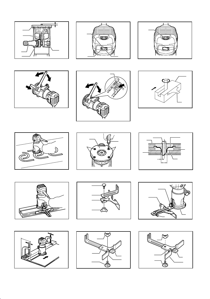
Adjusting bit protrusion
Fig.1
To adjust the bit protrusion, loosen the locking lever and
move the tool base up or down as desired by turning the
adjusting screw. After adjusting, tighten the locking lever
firmly to secure the tool base.
NOTE:
• When the tool is not secured even if the locking
lever is tightened, tighten the hex nut and then
tighten the locking lever.
Switch action
Fig.2
CAUTION:
• Before plugging in the tool, always check to see
that the tool is switched off.
To start the tool, press the "ON ( I )" side of the switch.
To stop the tool, press the "OFF (O)" side of the switch.
Electronic function
The tool equipped with electronic function are easy to
operate because of the following features.
Constant speed control
Electronic speed control for obtaining constant speed.
Possible to get fine finish, because the rotating speed is
kept constant even under load condition.
Soft start
Soft-start feature minimizes start-up shock, and makes
the tool start smoothly.
Speed adjusting dial
Fig.3
The tool speed can be changed by turning the speed
adjusting dial to a given number setting from 1 to 6.
Higher speed is obtained when the dial is turned in the
direction of number 6. And lower speed is obtained
when it is turned in the direction of number 1.
This allows the ideal speed to be selected for optimum
material processing, i.e. the speed can be correctly
adjusted to suit the material and bit diameter.
Refer to the table for the relationship between the
number settings on the dial and the approximate tool
speed.

10
Number min-1
1
2
3
4
5
6
10,000
30,000
12,000
17,000
22,000
27,000
011932
CAUTION:
• If the tool is operated continuously at low speeds
for a long time, the motor will get overloaded,
resulting in tool malfunction.
• The speed adjusting dial can be turned only as far
as 6 and back to 1. Do not force it past 6 or 1, or
the speed adjusting function may no longer work.
ASSEMBLY
CAUTION:
• Always be sure that the tool is switched off and
unplugged before carrying out any work on the
tool.
Installing or removing trimmer bit
Fig.4
Fig.5
CAUTION:
• Do not tighten the collet nut without inserting a bit,
or the collet cone will break.
• Use only the wrenches provided with the tool.
Insert the bit all the way into the collet cone and tighten
the collet nut securely with the two wrenches or by
pressing the shaft lock and using the provided wrench.
To remove the bit, follow the installation procedure in
reverse.
OPERATION
For the trimmer base
12
3
011989
WARNING:
• Before using the tool with the trimmer base,
always install the dust nozzle on the trimmer base.
Set the tool base on the workpiece to be cut without the
bit making any contact. Then turn the tool on and wait
until the bit attains full speed. Move the tool forward
over the workpiece surface, keeping the tool base flush
and advancing smoothly until the cutting is complete.
When doing edge cutting, the workpiece surface should
be on the left side of the bit in the feed direction.
12
3
44
2
001984
NOTE:
• Moving the tool forward too fast may cause a poor
quality of cut, or damage to the bit or motor.
Moving the tool forward too slowly may burn and
mar the cut. The proper feed rate will depend on
the bit size, the kind of workpiece and depth of cut.
Before beginning the cut on the actual workpiece,
it is advisable to make a sample cut on a piece of
scrap lumber. This will show exactly how the cut
will look as well as enable you to check
dimensions.
• When using the trimmer shoe, the straight guide or
the trimmer guide, be sure to keep it on the right
side in the feed direction. This will help to keep it
flush with the side of the workpiece.
Fig.6
CAUTION:
• Since excessive cutting may cause overload of the
motor or difficulty in controlling the tool, the depth
of cut should not be more than 3 mm at a pass
when cutting grooves. When you wish to cut
grooves more than 3 mm deep, make several
passes with progressively deeper bit settings.
Templet guide (optional accessory)
Fig.7
The templet guide provides a sleeve through which the
bit passes, allowing use of the trimmer with templet
patterns.
Loosen the screws and remove the base protector.
Place the templet guide on the base and replace the
base protector. Then secure the base protector by
tightening the screws.
1. Dust nozzle
2. Thumb screw
3. Trimmer base
1. Workpiece
2. Bit revolving direction
3. View from the top of the tool
4. Feed direction

11
Fig.8
Secure the templet to the workpiece. Place the tool on
the templet and move the tool with the templet guide
sliding along the side of the templet.
Fig.9
NOTE:
• The workpiece will be cut a slightly different size
from the templet. Allow for the distance (X)
between the router bit and the outside of the
templet guide. The distance (X) can be calculated
by using the following equation:
Distance (X) = (outside diameter of the templet guide -
router bit diameter) / 2
Straight guide (optional accessory)
Fig.10
The straight guide is effectively used for straight cuts
when chamfering or grooving.
Fig.11
Attach the guide plate to the straight guide with the bolt
and the wing nut.
Fig.12
Attach the straight guide with the clamp screw (A).
Loosen the wing nut on the straight guide and adjust the
distance between the bit and the straight guide. At the
desired distance, tighten the wing nut securely.
When cutting, move the tool with the straight guide flush
with the side of the workpiece.
If the distance (A) between the side of the workpiece
and the cutting position is too wide for the straight guide,
or if the side of the workpiece is not straight, the straight
guide cannot be used. In this case, firmly clamp a
straight board to the workpiece and use it as a guide
against the trimmer base. Feed the tool in the direction
of the arrow.
Fig.13
Circular work
Fig.14
Circular work may be accomplished if you assemble the
straight guide and guide plate as shown in the figures.
Min. and max. radius of circles to be cut (distance
between the center of circle and the center of bit) are as
follows:
Min.: 70 mm
Max.: 221 mm
For cutting circles between 70 mm and 121 mm in
radius.
For cutting circles between 121 mm and 221 mm in
radius.
Fig.15
NOTE:
• Circles between 172 mm and 186 mm in radius
cannot be cut using this guide.
Fig.16
Align the center hole in the straight guide with the center
of the circle to be cut. Drive a nail less than 6 mm in
diameter into the center hole to secure the straight
guide. Pivot the tool around the nail in clockwise
direction.
Trimmer guide (optional accessory)
Fig.17
Trimming, curved cuts in veneers for furniture and the
like can be done easily with the trimmer guide. The
guide roller rides the curve and assures a fine cut.
Fig.18
Install the trimmer guide on the tool base with the clamp
screw (A). Loosen the clamp screw (B) and adjust the
distance between the bit and the trimmer guide by
turning the adjusting screw (1 mm per turn). At the
desired distance, tighten the clamp screw (B) to secure
the trimmer guide in place.
Fig.19
When cutting, move the tool with the guide roller riding
the side of the workpiece.
Tilt base (optional accessory)
Tilt base (optional accessory) is convenient for
chamfering.
Fig.20
Place the tool onto the tilt base and close the locking
lever at the desired protrusion of the bit. For desired
angle, tighten the clamping screws on its sides.
Firmly clamp a straight board to the workpiece and use
it as a guide against the tilt base. Feed the tool in the
direction of the arrow.
Base protector removed from the tilt base
(optional accessory)
Mounting the base protector which has been removed
from the tilt base on the trimmer base allows the change
of the trimmer base from the round base to a square
base.
For another application, remove the base protector from
the tilt base by loosening and removing four screws.
Fig.21
And then mount the base protector on the trimmer base.
Offset base (optional accessory)
Fig.22
(1) Offset base (optional accessory) is
convenient for work in a tight area such as a
corner.
Fig.23
Before installing the tool on the offset base, remove the
collet nut and collet cone by loosening the collet nut.
Fig.24
Install the pulley on the tool by pressing the shaft lock
and firmly tightening the pulley with a wrench.

12
Fig.25
Place the collet cone and screw the collet nut on the
offset base as shown in the figure.
Fig.26
Mount the tool on the offset base.
Fig.27
Put an end of the belt over the pulley using a
screwdriver and make sure that its entire belt width fits
over the pulley completely.
Fig.28
Secure it with a locking lever on the offset base.
Fig.29
To install the bit, fall the tool with the offset base on its
side. Insert the hex wrench into the hole in the offset
base.
With the hex wrench held in that position, insert the bit
into the collet cone on the shaft of the offset base from
the opposite side and tighten the collet nut firmly with a
wrench.
To remove the bit at replacement, follow the installation
procedure in reverse.
(2) Offset base (optional accessory) can also be
used with a trimmer base and a grip
attachment (optional accessory) for more
stability.
Fig.30
Loosen the screws and remove the upper section from
the offset base. Put aside the upper section of the offset
base.
Fig.31
Mount the trimmer base with four screws and the grip
attachment (optional accessory) with two screws on the
offset base plate.
Screw a bar type grip (optional accessory) onto the grip
attachment.
Fig.32
In another way of use, the knob type grip which is
removed from a plunge base (optional accessory) can
be installed on the grip attachment. To install the knob
type grip, place it on the grip attachment and secure it
with a screw.
Fig.33
When using as a router only with a plunge
base (optional accessory)
CAUTION:
• When using as a router, hold the tool firmly with
both hands.
Fig.34
To use the tool as a router, install the tool on a plunge
base (optional accessory) by pressing it down fully.
Either knob type grip or bar type grip (optional
accessory) can be used according to your work.
Fig.35
To use the bar type grip (optional accessory), loosen the
screw and remove the knob type grip.
Fig.36
And then screw the bar type grip on the base.
Adjusting the depth of cut when using the plunge
base (optional accessory)
Fig.37
Place the tool on a flat surface. Loosen the lock lever
and lower the tool body until the bit just touches the flat
surface. Tighten the lock lever to lock the tool body.
Turn the stopper pole setting nut counterclockwise. Lower
the stopper pole until it makes contact with the adjusting
bolt. Align the depth pointer with the "0" graduation. The
depth of cut is indicated on the scale by the depth pointer.
While pressing the fast-feed button, raise the stopper
pole until the desired depth of cut is obtained. Minute
depth adjustments can be obtained by turning the
adjusting knob (1 mm per turn).
By turning the stopper pole setting nut clockwise, you
can fasten the stopper pole firmly.
Now, your predetermined depth of cut can be obtained
by loosening the lock lever and then lowering the tool
body until the stopper pole makes contact with the
adjusting hex bolt of the stopper block.
Always firmly hold the tool by both grip during operation.
Set the tool base on the workpiece to be cut without the bit
making any contact. Then turn the tool on and wait until the
bit attains full speed. Lower the tool body and move the tool
forward over the workpiece surface, keeping the tool base
flush and advancing smoothly until the cutting is complete.
When doing edge cutting, the workpiece surface should
be on the left side of the bit in the feed direction.
12
3
44
2
001984
NOTE:
•
Moving the tool forward too fast may cause a poor
quality of cut, or damage to the bit or motor. Moving
the tool forward too slowly may burn and mar the
cut. The proper feed rate will depend on the bit size,
the kind of workpiece and depth of cut. Before
beginning the cut on the actual workpiece, it is
advisable to make a sample cut on a piece of scrap
lumber. This will show exactly how the cut will look
as well as enable you to check dimensions.
1. Workpiece
2. Bit revolving direction
3. View from the top of the tool
4. Feed direction

13
• When using the straight guide, be sure to install it
on the right side in the feed direction. This will help
to keep it flush with the side of the workpiece.
Fig.38
Straight guide when using as a router
(needed to use with guide holder
(optional accessory))
The straight guide is effectively used for straight cuts
when chamfering or grooving.
1
2
3
4
5
6
7
8
011988
Install the straight guide on the guide holder (optional
accessory) with the wing nut.
Insert the guide holder into the holes in the plunge base
and tighten the wing bolts. To adjust the distance
between the bit and the straight guide, loosen the wing
nut. At the desired distance, tighten the wing nut to
secure the straight guide in place.
Straight guide (optional accessory)
Fig.39
The straight guide is effectively used for straight cuts
when chamfering or grooving.
Fig.40
To install the straight guide, insert the guide bars into
the holes in the plunge base. Adjust the distance
between the bit and the straight guide. At the desired
distance, tighten the wing bolts to secure the straight
guide in place.
When cutting, move the tool with the straight guide flush
with the side of the workpiece.
Fig.41
If the distance (A) between the side of the workpiece
and the cutting position is too wide for the straight guide,
or if the side of the workpiece is not straight, the straight
guide cannot be used. In this case, firmly clamp a
straight board to the workpiece and use it as a guide
against the router base. Feed the tool in the direction of
the arrow.
Templet guide (optional accessory)
Fig.42
The templet guide provides a sleeve through which the
bit passes, allowing use of the tool with templet patterns.
To install the templet guide, loosen the screws on the
tool base, insert the templet guide and then tighten the
screws.
Fig.43
Secure the templet to the workpiece. Place the tool on
the templet and move the tool with the templet guide
sliding along the side of the templet.
Fig.44
NOTE:
• The workpiece will be cut a slightly different size
from the templet. Allow for the distance (X)
between the bit and the outside of the templet
guide. The distance (X) can be calculated by using
the following equation:
Distance (X) = (outside diameter of the templet
guide - bit diameter) / 2
Dust nozzle sets
For the trimmer base
12
3
011989
1. Bolt
2. Guide holder
3. Wing nut
4. Bolt
5. Wing nut
6. Guide plate
7. Straight guide
8. Wing bolts
1. Dust nozzle
2. Thumb screw
3. Trimmer base

14
For the plunge base (optional accessory)
1
2
011853
Use the dust nozzle for dust extraction. Install the dust
nozzle on the tool base using the thumb screw so that
protrusion on the dust nozzle fit to the notch in the tool
base.
Then connect a vacuum cleaner to the dust nozzle.
Fig.45
MAINTENANCE
CAUTION:
• Always be sure that the tool is switched off and
unplugged before attempting to perform inspection
or maintenance.
• Never use gasoline, benzine, thinner, alcohol or
the like. Discoloration, deformation or cracks may
result.
Replacing carbon brushes
Fig.46
Remove and check the carbon brushes regularly.
Replace when they wear down to the limit mark. Keep
the carbon brushes clean and free to slip in the holders.
Both carbon brushes should be replaced at the same
time. Use only identical carbon brushes.
Fig.47
Use a screwdriver to remove the brush holder caps.
Take out the worn carbon brushes, insert the new ones
and secure the brush holder caps.
To maintain product SAFETY and RELIABILITY, repairs,
any other maintenance or adjustment should be
performed by Makita Authorized Service Centers,
always using Makita replacement parts.
OPTIONAL ACCESSORIES
CAUTION:
• These accessories or attachments are
recommended for use with your Makita tool
specified in this manual. The use of any other
accessories or attachments might present a risk of
injury to persons. Only use accessory or
attachment for its stated purpose.
If you need any assistance for more details regarding
these accessories, ask your local Makita Service Center.
• Straight & groove forming bits
• Edge forming bits
• Laminate trimming bits
• Straight guide assembly
• Trimmer guide assembly
• Trimmer base assembly
• Tilt base assembly
• Plunge base assembly
• Offset base assembly
• Templet guide
• Collet cone 6 mm
• Collet cone 6.35 mm (1/4")
• Collet cone 8 mm
• Collet cone 9.53 mm (3/8")
• Wrench 13
• Wrench 22
Trimmer bits
Straight bit
Fig.48
mm
DA L1L2
20 50 15
20 6
20E 1/4"
86
8E 1/4"
850 18
66
6E 1/4" 650 18
8860 25
011929
"U"Grooving bit
Fig.49
mm
DAL1L2
66
6E 1/4"
66028
R
3
006486
"V"Grooving bit
Fig.50
mm
DAL1L2
1/4" 20 50 15 90
006454
1. Dust nozzle
2. Thumb screw

15
Drill point flush trimming bit
Fig.51
mm
DAL1L2
66
6E 1/4"
66018
L 3
28
888 2060 35
011930
Drill point double flush trimming bit
Fig.52
mm
D A L 1 L 2 L 4
66
6E 1/4" 67040
L 3
12 14
88880952025
011931
Corner rounding bit
Fig.53
mm
DA1 L1L2 R
25 48 13 8
8R 6
8RE 1/4"
4R 6
4RE 1/4"
20
A 2
9
845 10
L 3
5
44
006489
Chamfering bit
Fig.54
mm
D A L 1 L 2 L 3
6
6
62049142
20 50 13 5
23 46 11 6 30
45
60
006462
Cove beading bit
Fig.55
mm
DAL1L2R
20 43 8 46
62548138
006464
Ball bearing flush trimming bit
Fig.56
mm
DAL1L2
6
1/4" 10 50 20
006465
Ball bearing corner rounding bit
Fig.57
mm
D A 1 A 2 L 1 L 2 L 3 R
6
6
1/4"
3.5 3
3.5 6
21
40 10
15 8 37 7
21 8
8 40 10 3.5 6
006466
Ball bearing chamfering bit
Fig.58
mm
D A 1 L 1
26 42
6
1/4" 45
60620
A 2
8
841
L 2
12
11
006467
Ball bearing beading bit
Fig.59
mm
D A 1 A 2 A 3 L 1 L 2 L 3 R
6
6
5.5 4
4.5
10
12 726 12 8 42
20 12 8 40
006468
Ball bearing cove beading bit
Fig.60
mm
D A 1 A 2 A 4 L 1 L 2 L 3 R
6
6
5.5 3
5
10
12 526 22 8 42
20 18 8
A 3
12
12 40
006469
Ball bearing roman ogee bit
Fig.61
mm
D A 1 A 2 L 1 L 2 L 3 R1 R2
6
6
2.5 4.5
3
4.5
4.5 626 8 42 12
20 8 40 10
006470
NOTE:
• Some items in the list may be included in the tool
package as standard accessories. They may differ
from country to country.

16
SLOVENŠČINA (izvirna navodila)
Razlaga splošnega pogleda
1-1. Izbočeni del nastavka
1-2. Osnovna plošča orodja
1-3. Merilna letev
1-4. Zaklepna ročica
1-5. Nastavitveni vijak
1-6. Šestroba matica
2-1. Stikalo
2-2. Stran OFF (O)
2-3. Stran ON ( I )
3-1. Številčnica za izbiro hitrosti
4-1. Priviti
4-2. Zrahljati
4-3. Držalo
5-1. Priviti
5-2. Zrahljati
5-3. Zapora vretena
6-1. Smer pomika
6-2. Smer vrtenja nastavka
6-3. Obdelovanec
6-4. Vzporedni prislon
8-1. Ščitnik osnovne plošče
8-2. Vijaki
8-3. Izvijač
9-1. Ploski nastavek
9-2. Osnovna plošča
9-3. Šablona
9-4. Razdalja (X)
9-5. Obdelovanec
9-6. Vodilo za šablone 10
9-7. Ščitnik osnovne plošče
11-1. Vijak z matico
11-2. Vodilna plošča
11-3. Vzporedni prislon
11-4. Krilna matica
12-1. Vpenjalni vijak (A)
12-2. Vzporedni prislon
12-3. Krilna matica
12-4. Osnovna plošča
14-1. Krilna matica
14-2. Vodilna plošča
14-3. Vzporedni prislon
14-4. Sredinska luknja
14-5. Vijak z matico
15-1. Krilna matica
15-2. Vodilna plošča
15-3. Vzporedni prislon
15-4. Sredinska luknja
15-5. Vijak z matico
16-1. Žebelj
16-2. Sredinska luknja
16-3. Vzporedni prislon
18-1. Vpenjalni vijak (A)
18-2. Nastavitveni vijak
18-3. Vpenjalni vijak (B)
18-4. Vodilo za prirezovanje
19-1. Obdelovanec
19-2. Nastavek
19-3. Kolešček vodila
20-1. Vpenjalna vijaka
21-1. Ščitnik osnovne plošče
21-2. Vijak
23-1. Jermenica
23-2. Vpenjalna matica
23-3. Vpenjalni stožec
24-1. Ključ
24-2. Jermenica
24-3. Zapora vretena
25-1. Vpenjalna matica
25-2. Vpenjalni stožec
27-1. Jermenica
27-2. Jermen
28-1. Zaklepna ročica
28-2. Odmično podnožje
29-1. Ključ
29-2. Inbus ključ
29-3. Nastavek
30-1. Vijaki
30-2. Plošča odmičnega podnožja
30-3. Zgornji del odmičnega podnožja
31-1. Palični ročaj (izbirni pripomoček)
31-2. Priključek ročaja
(izbirni pripomoček)
31-3. Plošča odmičnega podnožja
31-4. Sklop osnovne plošče rezkalnika
(izbirni pripomoček)
32-1. Vijak
32-2. Gumbni ročaj
32-3. Plošča odmičnega podnožja
34-1. Pogrezna osnovna plošča
34-2. Ročaj
35-1. Vijak
35-2. Ročica
36-1. Palični ročaj (izbirni pripomoček)
37-1. Nastavljalni gumb
37-2. Zaklepna ročica
37-3. Kazalec globine
37-4. Nastavljalna matica ustavljalnega
droga
37-5. Gumb za hiter pomik
37-6. Ustavljalni drog
37-7. Omejevalnik
37-8. Nastavljalni vijak
38-1. Smer pomika
38-2. Smer vrtenja nastavka
38-3. Obdelovanec
38-4. Vzporedni prislon
40-1. Meč
40-2. Krilni vijak
40-3. Vzporedni prislon
43-1. Vijak
43-2. Osnovna plošča
43-3. Šablona
44-1. Nastavek
44-2. Osnovna plošča
44-3. Šablona
44-4. Obdelovanec
44-5. Razdalja (X)
44-6. Zunanji premer vodila za šablone
44-7. Vodilo za šablone
46-1. Meja obrabljenosti
47-1. Izvijač
47-2. Pokrov krtačke

17
TEHNIČNI PODATKI
Model RT0700C
Zmogljivost obroča vpenjalne glave 6 mm, 8 mm, 1/4" ali 3/8"
Hitrost brez obremenitve (min-1) 10.000 - 30.000
Celotna dolžina 200 mm
Neto teža 1,8 kg
Varnostni razred /II
• Zaradi našega nenehnega programa raziskav in razvoja si pridržujemo pravico do spremembe tehničnih podatkov brez obvestila.
• Tehnični podatki se lahko razlikujejo od države do države.
• Teža je v skladu z EPTA-postopkom 01/2003
ENE010-1
Namenska uporaba
Orodje je namenjeno za poravnano prirezovanje in
profiliranje lesa, plastike in podobnih materialov.
ENF002-1
Priključitev na električno omrežje
Napetost električnega omrežja se mora ujemati s
podatki na tipski ploščici. Stroj deluje samo z enofazno
izmenično napetostjo. Stroj je v skladu z evropskimi
standardi dvojno zaščitno izoliran, zato se ga lahko
priključi tudi na vtičnice brez ozemljitvenega voda.
ENG905-1
Hrup
Tipični, z A ocenjeni vrednosti hrupa glede na EN60745:
Raven zvočnega tlaka (LpA): 82 dB (A)
Raven zvočne moči (LWA): 93 dB (A)
Odstopanje (K): 3 dB (A)
Uporabljajte zaščito za sluh
ENG900-1
Vibracije
Skupne vrednosti vibracij (vektorska vsota treh osi) po
EN60745:
Delovni način: vrtenje brez obremenitve
Oddajanje tresljajev (ah): 2,5 m/s2ali manj
Odstopanje (K): 1,5 m/s2
Delovni način : rezanje utorov v plošče MDF
Oddajanje tresljajev (ah): 3,5 m/s2
Odstopanje (K): 1,5 m/s2
ENG901-1
•
Navedena vrednost oddajanja vibracij je bila
izmerjena v skladu s standardnimi metodami
testiranja in se lahko uporablja za primerjavo orodij.
• Navedena vrednost oddajanja vibracij se lahko
uporablja tudi pri predhodni oceni izpostavljenosti.
OPOZORILO:
•
Oddajanje vibracij med dejansko uporabo električnega
orodja se lahko razlikuje od navedene vrednosti
oddajanja, odvisno od načina uporabe orodja.
• Upravljavec mora za lastno zaščito poznati
varnostne ukrepe, ki temeljijo na oceni
izpostavljenosti v dejanskih pogojih uporabe
(upoštevajočceloten delovni proces v trenutkih, ko
je orodje izključeno in ko deluje v prostem teku z
dodatkom časa sprožitve).
ENH101-14
Samo za evropske države
ES Izjava o skladnosti
Makita Corporation kot odgovorni proizvajalec
izjavlja, da je naslednji stroj Makita:
Oznaka stroja:
Rezkalnik
Št. modela / tip: RT0700C
del serijske proizvodnje in
Je skladen z naslednjimi evropskimi direktivami:
2006/42/ES
In je izdelan v skladu z naslednjimi standardi ali
standardiziranimi dokumenti:
EN60745
Tehnično dokumentacijo hrani naš pooblaščeni
predstavnik za Evropo.
Makita International Europe Ltd.
Michigan Drive, Tongwell,
Milton Keynes, MK15 8JD, England
14.10.2010
000230
Tomoyasu Kato
Direktor
Makita Corporation
3-11-8, Sumiyoshi-cho,
Anjo, Aichi, JAPAN
GEA010-1
Splošna varnostna opozorila za
električno orodje
OPOZORILO Preberite vsa varnostna opozorila
in navodila. Neupoštevanje opozoril in navodil lahko
vodi do električnega udara, požara, in/ali hudih telesnih
poškodb.
Shranite vsa opozorila in navodila za
kasnejšo uporabo.

18
GEB019-4
VARNOSTNA OPOZORILA ZA
REZALNIK
1. Električno orodje držite samo na izoliranih
držalnih površinah, saj se lahko rezalnik
dotakne lastnega kabla. Ob stiku z vodniki pod
napetostjo dobijo napetost vsi neizolirani kovinski
deli električnega orodja, zaradi česar lahko
uporabnik utrpi električni udar.
2. Uporabljajte sponke ali druge praktične
načine za pritrditev in podporo obdelovanca
na stabilno podlago.Če držite obdelovanec z
roko ali ga naslanjate na telo, je nestabilen in
lahko povzroči izgubo nadzora.
3. Med daljšo uporabo uporabljajte zaščito za
sluh.
4. Z nastavki ravnajte zelo previdno.
5. Pred uporabo skrbno preverite nastavek glede
obrabe, razpok ali poškodb. Takoj zamenjajte
počen ali poškodovan nastavek.
6. Izogibajte se rezanju žebljev. Pred delom
poiščite in odstranite vse žeblje iz
obdelovanca.
7. Trdno držite orodje.
8. Ne približujte rok vrtečim se delom.
9. Preden vklopite stikalo, se prepričajte, ali se
nastavek ne dotika obdelovanca.
10. Orodje naj nekaj časa deluje, preden ga
uporabite na dejanskem obdelovancu. Bodite
pozorni na vibracije ali majanje, ki bi lahko
kazalo na nepravilno nameščen nastavek.
11. Bodite pozorni na smer vrtenja nastavka in
smer pomika.
12. Orodja ne pustite delovati brez nadzora.
Dovoljeno ga je uporabljati samo ročno.
13. Orodje vedno izključite in počakajte, da se
nastavek popolnoma ustavi, preden ga
odstranite iz obdelovanca.
14. Takoj po končani obdelavi se ne dotikajte
nastavka; ta je lahko zelo vročin lahko
povzroči opekline kože.
15. Drsnika orodja ne mažite brezbrižno z
razredčilom, bencinom, oljem ali podobnimi
sredstvi. To lahko povzroči razpoke v drsniku
orodja.
16. Uporabite nastavke s pravilnim premerom osi,
ki so primerni za hitrost orodja.
17. Nekateri materiali vsebujejo kemikalije, ki so
lahko strupene. Bodite previdni in preprečite
vdihavanje prahu in stik s kožo. Upoštevajte
varnostne podatke dobavitelja materiala.
18. Vedno uporabite pravilno protiprašno
masko/respirator za material in uporabo.
SHRANITE TA NAVODILA.
OPOZORILO:
NE dopustite si, da bi zaradi udobnejšega dela ali
poznavanja izdelka (pridobljenega z večkratno
uporabo) opustili striktno upoštevanje varnostnih
pravil pri uporabi stroja. ZLORABA ali
neupoštevanje varnostnih pravil v teh navodilih za
uporabo lahko povzroči hude telesne poškodbe.
OPIS DELOVANJA
POZOR:
• Pred vsako nastavitvijo ali pregledom nastavitev
stroja se prepričajte, da je le to izključeno in
ločeno od električnega omrežja.
Prilagoditev izbočenega dela nastavka
Sl.1
Za prilagoditev izbočenega dela nastavka odvijte
zaklepno ročico in po želji premaknite osnovno ploščo
orodja gor ali dol, tako da zavrtite prilagoditveni vijak.
Po prilagoditvi trdno zategnite zaklepno ročico, da
pritrdite osnovno ploščo orodja.
OPOMBA:
• Če orodje ni trdno pritrjeno, tudi če je zaklepna
ročica zategnjena, zategnite šestrobo matico, nato
pa zategnite zaklepno ročico.
Delovanje stikala
Sl.2
POZOR:
• Preden priključite orodje se vedno prepričajte, ali
je orodje izklopljeno.
Za vklop orodja premaknite vklopno/izklopno stikalo v
stran „ON (I)". Za izklop orodja premaknite
vklopno/izklopno stikalo v stran „OFF (O)".
Elektronska funkcija
Orodja, opremljena z elektronsko funkcijo, so enostavna
za uporabo zaradi naslednjih značilnosti.
Uravnavanje konstantnega števila vrtljajev
Elektronski nadzor hitrosti za konstantno število vrtljajev.
Možnost fine končne obdelave, saj je hitrost rotacije
konstantna tudi v stanju obremenitve.
Mehki zagon
Funkcija mehkega zagona zmanjša sunek ob zagonu in
omogoči gladek zagon orodja.
Gumb za nastavitev hitrosti
Sl.3
Hitrost orodja lahko spremenite z obračanjem številčnice
za izbiro hitrosti na ustrezno številko od 1 do 6.
Višji hitrost dosežete, če številčnico obrnete v smeri številke
6. Nižjo hitrost dobite, če jo obrnete v smeri številke 1.
To omogoča izbiro idealen hitrosti za optimalno
obdelavo materiala, torej lahko hitrost pravilno nastavite,
da ustreza materialu in premeru nastavka.

19
Za razmerje med nastavitvijo številke in približno
hitrostjo orodja glejte tabelo.
Število min
-1
1
2
3
4
5
6
10.000
30.000
12.000
17.000
22.000
27.000
011932
POZOR:
• Če stroj dalj časa neprekinjeno deluje z nizkim
številom vrtljajev, pride do čezmerne obremenitve
motorja, zaradi česar lahko pride do okvare stroja.
• Številčnico za izbiro hitrosti lahko obrnete samo do
6 in nazaj do 1. Ne vrtite je prek 6 ali 1, ker morda
funkcija izbire hitrosti ne bo večdelovala.
MONTAŽA
POZOR:
• Pred vsakim posegom v orodje se prepričajte, da
je le to izključeno in ločeno od električnega
omrežja.
Namestitev ali odstranitev nastavka
rezkalnika
Sl.4
Sl.5
POZOR:
• Ne zategnite vpenjalne matice brez vstavljenega
nastavka, sicer se bo vpenjalni stožec zlomil.
• Uporabljajte le ključe, ki so priloženi orodju.
Nastavek vstavite do konca v vpenjalni stožec in trdno
zategnite vpenjalno matico z dvema ključema ali s
pritiskom na zaporo vretena in uporabo priloženega
ključa.
Za odstranjevanje nastavka izvedite postopek
namestitve v obratnem vrstnem redu.
DELOVANJE
Za osnovno ploščo rezkalnika
12
3
011989
OPOZORILO:
• Preden uporabite orodje z osnovno ploščo
rezkalnika, vedno namestite sesalni nastavek na
osnovno ploščo rezkalnika.
Postavite osnovno ploščo orodja na obdelovanec tako,
da se nastavek ne dotika obdelovanca. Nato vklopite
orodje in počakajte, da nastavek doseže polno število
vrtljajev. Orodje premaknite naprej po površini
obdelovanca, pri tem pa mora osnovna plošča orodja
plosko nalegati, dokler rez ni dokončan.
Robove posnemajte tako, da se površina obdelovanca,
gledano v smeri pomika, nahaja levo od nastavka.
12
3
44
2
001984
OPOMBA:
• Prehitro potiskanje orodja lahko poslabša
natančnost reza ali povzroči poškodbo nastavka
ali okvaro motorja. Če stroj potiskate prepočasi,
lahko rez povzroči nastanek ožganih mest ali
poškodb v obdelovancu. Pravšnja hitrost pomika
je vselej odvisna od velikosti nastavka, materiala
obdelovanca in globine reza. Pred začetkom
rezkanja je priporočljivo narediti poskusni rez na
vzorčnem, odpadnem kosu materiala, ki ga
obdelujete. Na ta način je najlažje oceniti učinek
rezkanja in preveriti mere obdelave.
1. Sesalna šoba
2. Krilati vijak
3. Osnovna
p
lošča rezkalnika
1. Obdelovanec
2. Smer vrtenja nastavka
3. Pogled na orodje od zgoraj
4. Smer pomika

20
•
Če delate z okovom rezalnika, vzporednim prislonom ali
vodilom za prirezovanje, ga obdržite na desni strani,
gledano v smeri pomika. S tem je zagotovljen tesen stik
med pripomočkom in stranskim robom obdelovanca.
Sl.6
POZOR:
• Dolgotrajno rezkanje lahko preobremeni motor in
povzroči težave z vodenjem orodja, zato pri
izdelavi utorov pazite, da nastavljena globina reza
ne bo večja od 3 mm na delovni korak. Če želite
rezati utore z globino nad 3 mm, zarežite večkrat s
postopnim večanjem nastavitve globine nastavka.
Vodilo za šablone (izbirni pripomoček)
Sl.7
Vodilo za šablone je opremljeno z vencem, skozi
katerega prehaja nastavek, kar omogoča uporabo
rezalnika s šablonskimi vzorci.
Odvijte vijake in odstranite ščitnik osnovne plošče.
Namestite vodilo za šablone na osnovno ploščo in
znova namestite ščitnik osnovne plošče. Nato pritrdite
ščitnik osnovne plošče, tako da zategnete vijake.
Sl.8
Pritrdite šablono na obdelovanca. Položite orodje na
šablono in ga pomikajte tako, da vodilo za šablone drsi
vzdolž bočne strani šablone.
Sl.9
OPOMBA:
• Rez v obdelovancu nekoliko odstopa od velikosti
šablone. Upoštevajte odmik (X) med rezkalnim
nastavkom in zunanjostjo vodila za šablone.
Odmik (X) se izračuna po spodnji enačbi:
odmik (X) = (zunanji premer vodila za šablone - premer
rezkalnega nastavka) / 2
Vzporedni prislon (izbirni pripomoček)
Sl.10
Vzporedni prislon je učinkovit pripomoček za
posnemanje robov ali izdelavo vzdolžnih rezov.
Sl.11
Priključite vodilno ploščo na vzporedni prislon z vijakom
in krilno matico.
Sl.12
Pritrdite vzporedni prislon z vpenjalnim vijakom (A).
Odvijte krilno matico in prilagodite razdaljo med
nastavkom in vzporednim prislonom. Pri želeni razdalji
trdno zategnite krilno matico.
Med rezanjem premikajte orodje z vzporednim
prislonom poravnano s stranico obdelovanca.
Če je razmik (A) med stranico obdelovanca in položajem
rezanja preširok za vzporedni prislon ali če stranica
obdelovanca ni ravna, vzporednega prislona ni mogoče
uporabiti. V tem primeru lahko kot pripomoček za vodenje
osnovne plošče rezkalnika uporabite kos ravne deske, ki jo
namestite na obdelovanec. Orodje pomikajte v smeri puščice.
Sl.13
Krožno rezkanje
Sl.14
Krožno rezkanje se lahko izvaja, če sestavite vzporedni
prislon in vodilno ploščo, kot je prikazano na slikah.
Najmanjši in največji polmer krogov, ki jih boste rezali
(razdalja med sredino kroga in sredino nastavka), so
naslednji:
najmanj: 70 mm
največ: 221 mm
Za rezanje krogov s polmerom med 70 in 121 mm.
Za rezanje krogov s polmerom med 121 in 221 mm.
Sl.15
OPOMBA:
• Krogov s polmerom med 172 in 186 mm ni
mogoče rezati z uporabo tega vodila.
Sl.16
Poravnajte sredinsko luknjo v vzporednem prislonu s
sredino kroga, ki ga boste rezali. Zabijte žebelj s
premerom manj kot 6 mm v sredinsko luknjo, da pritrdite
vzporedni prislon. Zavrtite orodje okrog žeblja v smeri
urinega kazalca.
Vodilo za prirezovanje (izbirni pripomoček)
Sl.17
Prirezovanje, ukrivljeni rezi v furnir pohištva in podobno
so z vodilom za prirezovanje enostavno izvedljivi.
Kolešček vodila sledi krivulji in zagotavlja natančen rez.
Sl.18
Namestite vodilo za prirezovanje na osnovno ploščo
orodja z vpenjalnim vijakom (A). Odvijte vpenjalni vijak
(B) in prilagodite razdaljo med nastavkom in vodilom za
prirezovanje, tako da zavrtite prilagoditveni vijak (1 mm
na obrat). Ko je želeni razmik nastavljen, zategnite
vpenjalni vijak (B), da pritrdite vodilo za prirezovanje.
Sl.19
Med rezanjem premikajte orodje s koleščkom vodila
poravnano s stranico obdelovanca.
Nagibna osnovna plošča (izbirni pripomoček)
Nagibna osnovna plošča (izbirni pripomoček) je priročna
za posnemanje.
Sl.20
Orodje namestite na nagibno osnovno ploščo in zaprite
zaklepno ročico na želeni izboklini nastavka. Za želen
kot zategnite vpenjalne vijake na straneh.
Trdno vpnite kos ravne deske na obdelovanec in ga
uporabite kot vodilo ob nagibni osnovni plošči. Orodje
pomikajte v smeri puščice.
Ščitnik osnovne plošče odstranjen z nagibne
osnovne plošče (izbirni pripomoček)
Nameščanje ščitnika osnovne plošče, ki je bil
odstranjen z nagibne osnovne plošče na osnovni plošči
rezkalnika omogoča spremembo osnovne plošče
rezkalnika iz okrogle v kvadratno osnovno ploščo.
Other manuals for RT0700C
13
Table of contents
Languages:
Other Makita Trimmer manuals

Makita
Makita UH4570 User manual

Makita
Makita UH6300 Manual

Makita
Makita RST210 User manual

Makita
Makita UR013G User manual

Makita
Makita HU02 User manual

Makita
Makita UH4570 User manual

Makita
Makita RT0700C User manual

Makita
Makita UH4570 User manual

Makita
Makita ur3000 User manual

Makita
Makita XHU02 User manual

Makita
Makita RBC2510 Quick start guide

Makita
Makita UR100D User manual

Makita
Makita EX2650LH User guide

Makita
Makita DUR184L User manual

Makita
Makita UR008G User manual

Makita
Makita UR002GD201 User manual

Makita
Makita EM4351UH User guide

Makita
Makita DUN600L User manual

Makita
Makita 3711 User manual

Makita
Makita DUR181RT Manual