Malyan MA10 User manual

User’s Manual

CONTENTS
SAFETY WARNINGS AND GUIDELINES
INTRODUCTION
FEATURES
CUSTOMER SERVICE
PACKAGE CONTENTS
PRODUCT OVERVIEW
INSTALLATION
SETUP
OPTIONAL WI-FI SETUP
SOFTWARE INSTALLATION AND SETUP
INSTALLING Cura
Repetier-Host
TECHNICAL SUPPORT
REGULATORY COMPLIANCE
NOTICE FOR FCC
EU DECLARATION OF CONFORMITY
02
19
19
20
17
13
13
12
8
18
7
6
5
5
4
4
3

Be careful not to damage the PC paper on the build plate.
Take care to avoid touching hot parts, including heat blocks, extruder nozzle,
extruded lament, and the heated build plate.
Do not wear gloves when operating or repairing to avoid entanglement.
Keep the printer and all accessories out of reach of children.
Do not remove or disconnect the USB cable when printing from a computer.
Do not pull or twist the black cable at any time.
Do not force or tear anything during unpacking and setup. This may cause
damage to the printer and/or its accessories.
Do not reach inside the printer during operation.
Always allow the printer and extruded lament to cool before reaching inside.
Ensure that the printer is turned o and unplugged from its power source
before making repairs or performing service.
Do not install this device on an unstable surface where it could fall and cause
either personal injury or damage to the device and/or other equipment.
Do not subject the product to extreme force, shock, or uctuations in
temperature or humidity.
This device is intended for indoor use only.
Do not expose this device to water or moisture of any kind. Do not place
drinks or other containers with moisture on or near the device. If moisture
does get in or on the device, immediately unplug it from the power outlet
and allow it to fully dry before reapplying power.
Do not touch the device, the power cord, or any other connected cables
with wet hands.
Use only in a well-ventilated area. Do not use in close, conned spaces.
SAFETY WARNINGS AND GUIDELINES
03

Prior to operation, check the unit and power cord for physical damage.
Do not use if physical damage has occurred.
Before plugging the unit into a power outlet, ensure that the outlet
provides the same type and level of power required by the device.
Unplug this device from the power source when not in use.
Take care to prevent damage to the power cord. Do not allow it to
become crimped, pinched, walked on, or become tangled with other
cords. Ensure that the power cord does not present a tripping hazard.
Never unplug the unit by pulling on the power cord. Always grasp the
connector head or adapter body.
04
INTRODUCTION
Thank you for purchasing this 3D printer from MALYAN! This printer
features a single extruder, which is capable of printing in PLA, ABS,
and other materials. You can print from a Windows® or Mac® PC
using a USB connection or can print from 3D model les stored on a
memory card, without the need for a PC connection of any kind. This
printer is easy to setup and easy to use following the instructions in
this manual.
FEATURES
Single extrusion print head
Can print PLA, ABS, wood, Copper Fill, Steel Fill, Bronze Fill, and other
materials
Open frame design for ease of use and maintenance
Includes a memory card with Cura, Repetier-Host, and a sample 3D model
3
1
4
2

The MALYAN Customer Service department is dedicated to ensuring that y
our ordering, purchasing, and delivery experience is second to none.
If you have any problem with your order, please give us an opportunity to
make it right. You can contact a MALYAN Customer Service representative
Please take an inventory of the package contents to ensure you have all
the items listed below. If anything is missing or damaged, please contact
MALYAN Customer Service for a replacement.
1x 3D printer
1x Filament rack
1x Plastic scraper
1x USB cable
1x MicroSD card
4x Hex wrench (2mm, 2.5mm, 3mm, 4mm)
5x M5x20 screw
5x M4x6 screw
1x Open-end wrench (8mm)
1x AC power cord
1x User's manual
05
PACKAGE CONTENTS
CUSTOMER SERVICE
1
1
2
3
5
6
4

1. Extruder 2. LCD screen
3. Filament rack 4. Feed Mechanism
5. Micro USB and microSD™ports 6. Power switch
7. AC power connector
PRODUCT OVERVIEW
06
56
7
3
1
4
2
All instructions assume you are looking at the front of the printer during
assembly.
1. Use the packaging material to lay the printer on its side so that you can
see the holes on the bottom. Position the vertical portion of the frame
opposite the holes in the bottom, align the holes on the bottom of the
vertical frame with those on the horizontal frame, then use the included
2.5mm hex wrench and 4x M5x20 screws to secure the vertical frame
to the horizontal frame (2 screws on each side).
2. Place the printer on its feet so that you have access to both sides.
The Z Axis Lead Screw is stored inside the Left Y Axis Carriage Bar
and is secured in place using two plastic brackets. Use the 2.5mm hex
wrench to remove the plastic brackets. You will need to move the bed
backward to access the rear most bracket. Remove the Z Axis Lead
INSTALLATION
07
1
1
2
3
5
6
4

Screw from the Left Y Axis Carriage Bar, then replace the plastic
brackets and tighten the screws to secure them in place.
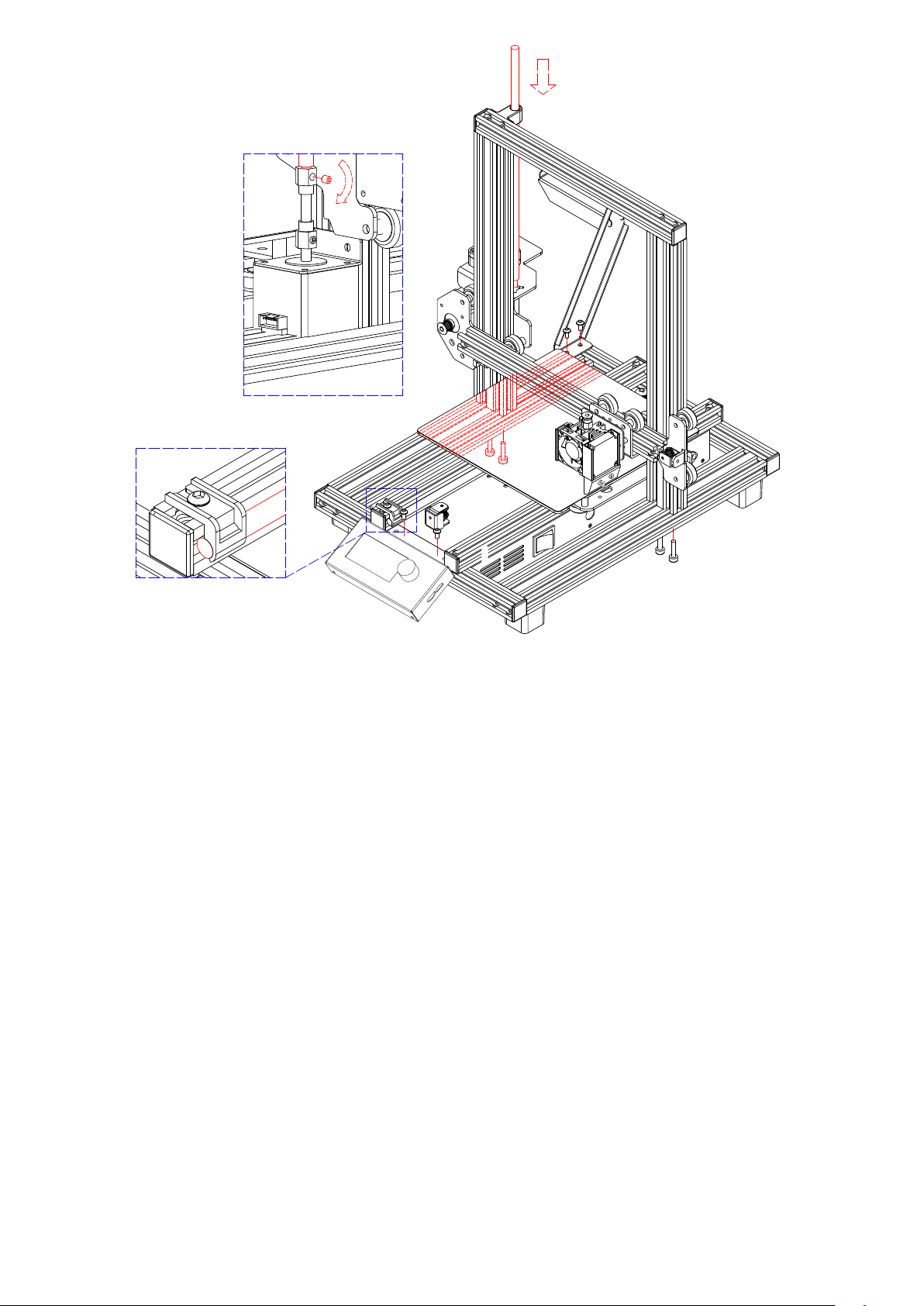
Using the included 3mm hex wrench, loosen the screw in the top of
the motor coupling, so that the Z Axis Lead Screw can be inserted.
Insert the Z Axis Lead Screw through the hole in the top of the frame,
then thread the it through the hole on the extruder housing until the
unthreaded portion of the screw is fully inserted into the motor coupling.
When it is properly inserted, the top will be ush with the frame. Tighten
the screw loosened in the previous step to secure the Z Axis Lead Screw
to the motor.
Using the 2.5mm hex wrench and 2x M4x6 screws, x the LCD Display
Module to the the printer frame. Insert the plug into the back of the module.
Align the t-nuts in the frame with the holes on the lament holder, then
using the 2.5mm hex wrench and 2x M4x6 screws, secure the lament
holder to the frame.
Mount the extruder hotend to the bracket on the X Axis Gantry by aligning
the positioning rods and magnets. Ensure that the cables are on top.
Plug the three cable connectors into the appropriate connections on the
front left side of the Left Y Axis Carriage, beneath the Z Axis Lead Screw
storage location referenced in step 3 above.
SETUP
Perform the following steps to prepare the printer for use.
1. Put the printer on a at, stable surface with plenty of ventilation and a
nearby AC power outlet.
2. Ensure that the Power Switch is in the OFF position. Plug the included
AC Power Cord into the AC Power Connector jack on the right side of the
08
3.
4.
5.
6.
7.
8.
Warning! Take care not to remove or damage the printing surface on the build
platform. This paper is essential to ensure the 3D model properly adheres to
the build platform during printing.

printer, then plugthe other end into a nearby AC power outlet. Flip the
Power Switch to the ON position.
Insert the included memory card into the slot on
the right side of the LCD module, the main
menu will display on the screen.
Press the center of control wheel and the contents
as the following picture will display on the screen.
Please rotating the control wheel clockwise to
choose the Change SD card if No SD card show
on the screen instead of Print from SD.
Rotating the control wheel clockwise to move
the highlight to Prepare, press the center of
control wheel to enter the menu.
Rotating the control wheel clockwise to move
the highlight to Auto home, the printer will move
the extruder to the home position automatically.
Check the distance between nozzle and platform,
if it is incorrect, please rotating the screw on the
bottom of four corners of the platform to adjust
the height of platform.
Rotating the control wheel counterclockwise to
move the highlight to Main, press the center of
the control wheel to back to the previous menu.
Rotating the control wheel clockwise to move
the highlight to the Control and press the center
of the control wheel to enter the menu.
09
3.
4.
5.
6.
7.
8.

Rotating the control wheel clockwise to move the highlight to Nozzle and press
the center of control wheel to enter the menu, Rotating the control wheel to set
the temperature of the nozzle to your target value, it depends on the lament you
plan to use. After you set up your target value, press the center of control wheel
Using the same procedure, set the Bed temperature to the target temperature
for your lament type.
Rotating the control wheel counterclockwise to move the highlight to Control,
press the center of control wheel to back to the previous menu.
While the printer is heating, open your lament. Using a pair of scissors or side
cutters, diagonally snip the end of the lament to make a point, as shown in the
images below.
Place the lament reel on the lament rack
on the left side of the printer.
While squeezing the lever on the Feed
Mechanism, insert the lament and push it into
opening. Keep pushing until you feel
resistance as it hits the extruder. Release the
lever on the Feed Mechanism.
10
9.
10.
11.
12.
13.
14.
Other manuals for MA10
1
Table of contents
Other Malyan 3D Printer manuals


