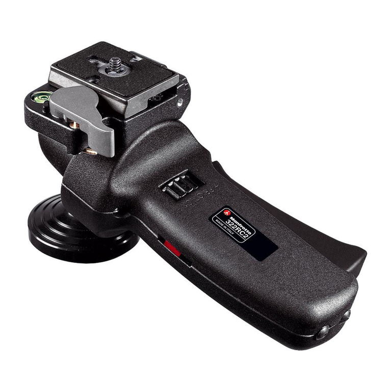
The shutter release mechanism is
supplied unassembled, and comprises
the following parts :
- button “A”
- casing “B” for use with the 322RC2
head in horizontal position
- casing “C” for use with the 322RC2
head in vertical position
- allen key “D”
- two screws “E“ with countersunk
heads
- one screw “F” with flat pan heads
MOUNTING THE SHUTTER
RELEASE MECHANISM TO THE
HEAD USED IN RIGHT-HANDED
HORIZONTAL POSITION
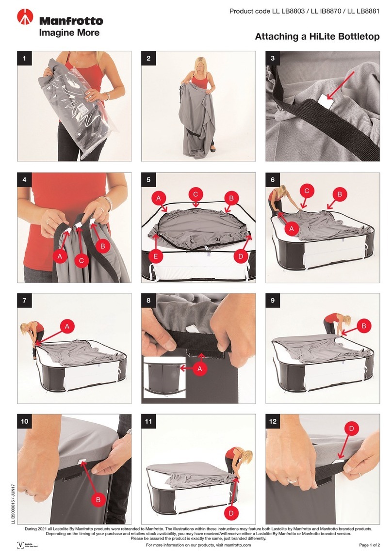
Attach casing “B” to the head as
shown in figure 2; tighten screw “F”
using the supplied allen key “D”. Slide
the button “A” into the casing as
shown
MOUNTING THE SHUTTER
RELEASE MECHANISM TO THE
HEAD USED IN LEFT-HANDED
HORIZONTAL POSITION
Attach casing “B” to the head as
shown in figure 3; tighten screws “E”
using the supplied allen key “D”. Slide
the button “A” into the casing as
shown.
MOUNTING THE SHUTTER
RELEASE MECHANISM TO THE
HEAD USED IN RIGHT-HANDED
VERTICAL POSITION
Attach casing “C” to the head as
shown in figure 4; tighten screws “E”
using the supplied allen key “D”. Slide
the button “A” into the casing as
shown.
MOUNTING THE SHUTTER
RELEASE MECHANISM TO THE
HEAD USED IN LEFT-HANDED
VERTICAL POSITION
Attach casing “C” to the head as
shown in figure 5; tighten screw “F”
using the supplied allen key “D”. Slide
the button “A” into the casing as
shown.
AB C D F
DE
AA
E
22
1
D
F
A
CC
1
2
1
B
ED
F
D
1
A
2
B
1
2 3
4 5
Ce kit télécommande de déclenche-
ment électronique est fourni non
monté. Il se compose des pièces sui-
vantes :
- bouton de déclenchement “A” avec
câble
- bague de fixation “B” pour utilisation
avec la rotule 322RC2 en position
horizontale
- bague de fixation “C” pour
utilisation avec la rotule 322RC2 en
position verticale
- clé allen “D”
- deux vis “E” à tête fraisée
- une vis “F” à tête plate
FIXATION DU KIT DÉCLENCHEUR
À LA ROTULE EN POSITION
HORIZONTALE
POUR DROITIERS
Fixez la bague de fixation “B” à la
rotule avec les deux vis “E” à l’aide
de la clé allen “D” fournie (cf. fig. 2).
Insérez le bouton de déclenchement
“A” dans la bague de la manière
illustrée.
FIXATION DU KIT DÉCLENCHEUR
À LA ROTULE EN POSITION
HORIZONTALE
POUR GAUCHERS
Fixez la bague de fixation “B” à la
rotule avec les deux vis “E” à l’aide
de la clé allen “D” fournie (cf. fig. 3).
Insérez le bouton de déclenchement
“A” dans la bague de la manière
illustrée.
FIXATION DU KIT DÉCLENCHEUR
À LA ROTULE EN POSITION
VERTICALE POUR DROITIERS
Fixez la bague de fixation “C” à la
rotule avec la vis “F” à l’aide de la clé
allen “D” fournie (fig. 4). Insérez le
bouton de déclenchement “A” dans la
bague de la manière illustrée.
FIXATION DU KIT DÉCLENCHEUR
À ROTULE EN POSITION
VERTICALE POUR GAUCHERS
Fixez la bague de fixation “C” à la
rotule avec la vis “F” à l’aide de la clé
allen “D” fournie (fig. 5). Insérez le
bouton de déclenchement “A” dans la
bague de la manière illustrée.
Der Auslöser wird nicht montiert
geliefert und umfasst folgende
Teile :
- Knopf “A”
- Gehäuse “B” zur Verwendung des
Stativkopfes 322RC2 im Querformat
- Gehäuse “C” zur Verwendung des
Stativkopfes 322RC2 im
Hochformat
- Steckschlüssel “D”
- Zwei Senkkopfschrauben “E”
- Eine Flachkopfschraube “F”
ANBINGUNG DES AUSLÖSERS AM
STATIVKOPF IN STELLUNG FÜR
RECHTSHÄNDIGE BEDIENUNG
UND QUERFORMAT
Bringen Sie Gehäuse “B” gemäß Abb.
2 am Stativkopf an. Ziehen Sie
Schrauben “E” mit dem mitgelieferten
Steckschlüssel “D” an. Schieben Sie
Knopf “A” wie abgebildet in das
Gehäuse.
ANBRINGUNG DES AUSLÖSERS
AM STATIVKOPF IN STELLUNG
FÜR LINKSHÄNDIGE BEDIENUNG
UND QUERFORMAT
Bringen Sie Gehäuse “B” gemäß Abb.
3 am Stativkopf an. Ziehen Sie
Schrauben “E” mit dem mitgelieferten
Steckschlüssel “D” an. Schieben Sie
Knopf “A” wie abgebildet in das
Gehäuse.
ANBRINGUNG DES AUSLÖSERS
AM STATIVKOPF IN STELLUNG
FÜR RECHTSHÄNDIGE
BEDIENUNG UND HOCHFORMAT
Bringen Sie das Gehäuse “C” gemäß
Abb. 4 am Stativkopf an. Ziehen Sie
Schraube “F” mit dem mitgelieferten
Steckschlüssel “D” an. Schieben Sie
Knopf “A” wie abgebildet in das
Gehäuse.
ANBRINGUNG DES AUSLÖSERS
AM STATIVKOPF IN STELLUNG
FÜR LINKSHÄNDIGE BEDIENUNG
UND HOCHFORMAT
Bringen Sie das Gehäuse “C” gemäß
Abb. 5 am Stativkopf an. Ziehen Sie
Schraube “F” mit dem mitgelieferten
Steckschlüssel “D” an. Schieben Sie
Knopf “A” wie abgebildet in das
Gehäuse.
El mecanismo de liberación del
obturador se proporciona sin montar,
y contiene las siguientes partes :
- botón “A”
- carcasa “B” para usar con la rótula
322RC2 en posición horizontal
- carcasa “C” para usar con la
322RC2 en posición vertical
- llave allen “D”
- dos roscas “E” con rótulas
encastradas
- un rosca “F” con rótula panorámica
plana
MONTANDO EL MECANISMO DE
LIBERACIÓN DEL OBTURADOR A
LA RÓTULA USADA EN POSICIÓN
HORIZONTAL PARA LA MANO
DERECHA
Una la carcasa “B” a la rótula (fig. 2);
apriete los roscas “E” usando la llave
allen “D” proporcionada. Deslice el
botón “A” en la carcasa como se
muestra.
MONTANDO EL MECANISMO DE
LIBERACIÓN DEL OBTURADOR A
LA RÓTULA USADA EN POSICIÓN
HORIZONTAL PARA LA MANO
IZQUIERDA
Una la carcasa “B” a la rótula (fig. 3);
apriete los roscas “E” usando la llave
allen “D” proporcionada. Deslice el
botón “A” en la carcasa como se
muestra.
MONTANDO EL MECANISMO DE
LIBERACIÓN RÁPIDO A LA RÓTULA
USADA EN POSICIÓN VERTICAL
PARA LA MANO DERECHA
Una la carcasa “C” a la rótula (fig. 4);
apriete la rosca “F” usando la llave
allen “D” proporcionada. Deslice el
botón “A” en la carcasa como se
muestra.
MONTANDO EL MECANISMO DE
LIBERACIÓN DEL OBTURADOR A
LA RÓTULA USADA EN POSICIÓN
VERTICAL PARA LA MANO
IZQUIERDA
Una la carcasa “C” a la rótula (fig. 5);
apriete la rosca “F” usando la llave
allend “D” proporcionada. Deslice el
botón “A” en la carcasa como se
muestra.
