manuals.online logo
Brands
  1. Home
  2. •
  3. Brands
  4. •
  5. Manrose
  6. •
  7. Fan
  8. •
  9. Manrose Classic Series User manual

Manrose Classic Series User manual

Yellow - Switched Live
Orange - Permanent Live
Black - Neutral
INTERNAL WIRING
DETAILED VIEW
Only Adjust with power switched off.
Timer Adjustment Any fan with a time delay tted will run approximately one minute after it has been switched off. The
time delay can be increased by rstly switching off the power to the fan, remove front cover, and insert a small allen key
in to the slot, marked in Diagram 3A, and turning clockwise to reduce the time and anti-clockwise to increase the
time. Only adjust with power switched off.
The minimum time the timer will run for is 20 seconds and the maximum is about 30 minutes.
NOTE: (i) The fan is to be installed so that the blades are 2.1m above the oor. For best results
this Extractor Fan should be tted as high on the wall as possible, or if preferred, on the
ceiling.
(ii) Do not install the unit within a shower cubicle. Use our shower fan SF150 models
(iii) Switch off mains supply before making electrical connections. This system should
be installed by a qualied electrician.
(iv) This fan is double insulated and does not require an earth.
(v) When installing fan through an external wall, an external wall grille must be tted
at all times.
DIAGRAM 3: Auto Shutter Models
DIAGRAM 3A: Timer Adjustment for Auto Shutter Fans
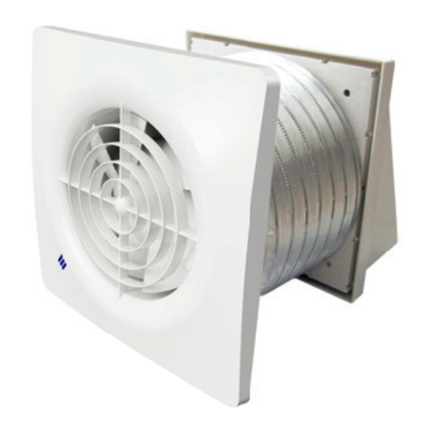
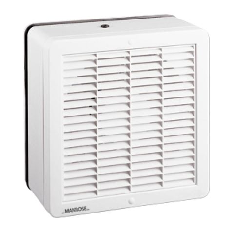
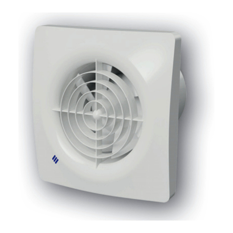
Thank you for selecting our Manrose 150mm Wall/Ceiling Fan.
Please read all instructions before commencing installation.
1. Cut a 160mm diameter hole in the wall. If the fan is to be xed onto the ceiling ensure that
the hole is between the joists.
2. Fit 150mm ducting ush to the plaster.
3. Remove the cover from the fan by simply unclipping the fascia. The front cover screw and
plug are conveniently located within the fan housing as shown in diagram 1 & 2.
4. Hold the body of the fan against the wall or ceiling and mark the four screw holes and the
cable entry. IMPORTANT: Ensure that the fan is square on wall or ceiling.
5. Bring power cable into position, as marked. Allow an extra 230mm (9”) protruding to
facilitate connection. Fan should only be installed by xed wiring, a exible cord should not
be used.
6. If an XP150 kit - Select a suitable position on the outside wall for the weatherproof cowl.
Carefully remove the cowl from its housing by levering gently at the sides with a small
screwdriver. Cut a 160mm hole ensuring rst that the area is free from obstruction.
7. Wiring of Standard/Pullcord Model (see diagram 1)
(Pullcord model unsuitable for ceiling mounting)
The fan can be connected to the light switch so that the fan will start when the light is
switched on. The fan should not be accessible to a person using either the shower or the bath.
NOTE: All wiring must be xed securely and the cable to the fan should be a minimum of 1mm2
in section. All wiring must comply with current Regulations. This system should be installed by a
qualied electrician.
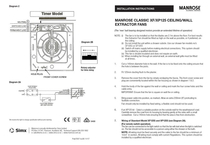
8. Wiring of Timer Model (see diagram 2).
The fan can be connected to the light switch so that the fan will start when the light is
switched on. When the light switch or pullcord is switched off the fan will run for between 20
sec & 30 minutes (pre-set to 1 minute). The fan should not be accessible to a person using
either the shower or the bath.
FAN0120/0127/0135/0136 Wall Fan and Kits
INSTALLATION INSTRUCTIONS CLASSIC SERIES
IMPORTANT NOTE:
If your fan is equipped
with auto shutters it will
be tted with a thermally
activated mechanism
that opens and closes
the shutters. When the
unit is turned on/off the
automatic shutters will
take approximately 45
seconds to respond.
Manrose is proudly distributed by Ventair Pty Ltd
4 Capital Place, Carrum Downs, 3201 VIC, AUSTRALIA.
Technical Support (03) 9775 0556
e: info@ventair.com.au | www.ventair.com.au | www.manrose.com.au
We reserve the right to change specication without prior warning
FAN0120/0127/0135/0136 Wall Fan and Kits IM Iss:01 03/20
Specications:
Model: NZNVF150SBB; NZNVF150TBB; NZXF150ABB; NZXF150ATBB
Electrical: 220-240V ~ 50Hz
Fan Wattage: 25W (45W for auto shutter model)
Max Temp: 40˚C
Airow: 87l/s (313m3 hr) - free air performance
Max Pressure: 60 Pa
Sound Volume: 40 dB(A)
IP Rated: IP44 (except pullcord model IP24)
IMPORTANT
• Isolate the mains supply before making any electrical connections. This system
should be installed by a qualied electrician.
• When tting through an external wall, an external grille must be tted at all times.
• Fan should only be installed by xed wiring, a exible cord should not be used.
• The appliance is not intended for use by young children or inrm persons without supervision.
• Young children should be supervised to ensure that they do not play with the appliance.
• Precautions must be taken to avoid the back-ow of gases into the room from
the open ue of gas or other open-re appliances when mounted in outside
windows or walls.
DIAGRAM 1: Standard & Pullcord Models:
DIAGRAM 2: Timer Models (XF/XP150)
Diagram 2A
Rotary adjuster
for time delay
NOTE: All wiring must be xed securely and the cable to the fan should be a minimum of 1mm2
in section. All wiring must comply with current Regulations. This system must be installed by a
qualied electrician.
Timer Adjustment
This time delay can be adjusted by rstly switching off the power to the fan and removing the
fascia. Locate the rotary adjuster as shown in Diagram 2. The serrated adjuster wheel can be
rotated using a thumbnail to adjust the timer setting.
+ = Rotate to the right to increase the time (indicated by + on the diagram)
- = Rotate to the left to decrease the time (indicated by - on the diagram)
Only adjust with power switched off.
9. Wiring of Autoshutter Models (see diagram 3)
(This model is unsuitable for ceiling mounting) This fan has its own integral pullcord on/off
switch. The fan should not be accessible to a person using either the shower or the bath.
NOTE: All wiring must be xed securely and the cable to the fan should be a minimum of
1mm2 in section. All wiring must comply with current Regulations. This system should be
installed by a qualied electrician.
10. Wiring of Auto shutter Model (see diagram 3A)
When light switch or pullcord is switched off fan will run for a between 20 sec and 30 mins
(pre-set to 1 minute). The fan should not be accessible to a person using either the shower
or the bath.
NOTE: All wiring must be xed securely and the cable to the fan should be a minimum of
1mm2 in section. All wiring must comply with current Regulations. This system should
be installed by a qualied electrician.

This manual suits for next models

8

Other Manrose Fan manuals

Manrose PRO Series User manual

Manrose

Manrose PRO Series User manual

Manrose PRO Series User manual

Manrose

Manrose PRO Series User manual

Manrose MET Series Assembly instructions

Manrose

Manrose MET Series Assembly instructions

Manrose FAN7500 User manual

Manrose

Manrose FAN7500 User manual

Manrose FAN7191 User manual

Manrose

Manrose FAN7191 User manual

Manrose FAN5375 User manual

Manrose

Manrose FAN5375 User manual

Manrose FAN0531 User manual

Manrose

Manrose FAN0531 User manual

Manrose Showerlite LEDSLKTC User manual

Manrose

Manrose Showerlite LEDSLKTC User manual

Manrose intellivent 2.0 User manual

Manrose

Manrose intellivent 2.0 User manual

Manrose FAN2120 User manual

Manrose

Manrose FAN2120 User manual

Manrose LED Series Installation guide

Manrose

Manrose LED Series Installation guide

Manrose PURO DCT4565 User manual

Manrose

Manrose PURO DCT4565 User manual

Manrose VIVO FAN7291 User manual

Manrose

Manrose VIVO FAN7291 User manual

Manrose FAN2040 User manual

Manrose

Manrose FAN2040 User manual

Manrose FAN7189 User manual

Manrose

Manrose FAN7189 User manual

Manrose FAN0085 User manual

Manrose

Manrose FAN0085 User manual

Manrose CLASSIC XF125 User manual

Manrose

Manrose CLASSIC XF125 User manual

Manrose FAN0148 User manual

Manrose

Manrose FAN0148 User manual

Manrose Aria 250 Motor User manual

Manrose

Manrose Aria 250 Motor User manual

Manrose M200P User manual

Manrose

Manrose M200P User manual

Manrose CQF100 User manual

Manrose

Manrose CQF100 User manual

Manrose SLIM F100 User manual

Manrose

Manrose SLIM F100 User manual

Manrose FAN0531 User manual

Manrose

Manrose FAN0531 User manual

Manrose FAN7180 User manual

Manrose

Manrose FAN7180 User manual

Popular Fan manuals by other brands

Vortice VORT PRESS 110 LL Instruction booklet

Vortice

Vortice VORT PRESS 110 LL Instruction booklet

Fanmaster IWEL200 instruction manual

Fanmaster

Fanmaster IWEL200 instruction manual

AC Infinity CLOUDLINE PRO S Series user manual

AC Infinity

AC Infinity CLOUDLINE PRO S Series user manual

Lervia LERVIA KH 1150 operating instructions

Lervia

Lervia LERVIA KH 1150 operating instructions

Smaair WGS-484CL installation guide

Smaair

Smaair WGS-484CL installation guide

FUAVE SV5010 instruction manual

FUAVE

FUAVE SV5010 instruction manual

Itho Daalderop CVE-S ECO instruction manual

Itho Daalderop

Itho Daalderop CVE-S ECO instruction manual

Hunter 23298 Installating and operation manual

Hunter

Hunter 23298 Installating and operation manual

Eglo BONDI Series instruction manual

Eglo

Eglo BONDI Series instruction manual

Hunter Hunter Ceiling Fan user manual

Hunter

Hunter Hunter Ceiling Fan user manual

Nibe SAM 42 user manual

Nibe

Nibe SAM 42 user manual

Natural Light Gable Solar Attic Fan installation instructions

Natural Light

Natural Light Gable Solar Attic Fan installation instructions

Monte Carlo Fan Company 5KBR54 Series owner's manual

Monte Carlo Fan Company

Monte Carlo Fan Company 5KBR54 Series owner's manual

Caframo Sirocco II Elite operating instructions

Caframo

Caframo Sirocco II Elite operating instructions

Hunter Hardwick 50593 installation manual

Hunter

Hunter Hardwick 50593 installation manual

Clas Ohlson TBK-F04 instruction manual

Clas Ohlson

Clas Ohlson TBK-F04 instruction manual

Optimus F-7585WH Instruction manual and owner's guide

Optimus

Optimus F-7585WH Instruction manual and owner's guide

HOMCOM 820-297V90 manual

HOMCOM

HOMCOM 820-297V90 manual

manuals.online logo
manuals.online logoBrands
  • About & Mission
  • Contact us
  • Privacy Policy
  • Terms and Conditions

Copyright 2025 Manuals.Online. All Rights Reserved.