Mark MRACK 12E User manual
MRACK 12E
User Manual –Version 1.0

1
SAFETY INSTRUCTIONS
1. Read the instructions of this manual.
2. Keep these instructions in a safe place.
3. Heed and follow all warnings and instructions.
4. Please, respect your country safety regulations.
5. Don’t use this device close to the water or high humidity places. Clean only with dry cloth.
6. Don’t install near any heat sources such as radiators, heat registers, stoves, or other apparatus (including
amplifiers) that produce heat. Make certain that the equipment is always installed so that is cooled and
can’t overheat.
7. Don’t block any ventilation openings. Install in accordance with the manufacturer’s instructions.
8. Protect the power cord from being walked on or pinched, particularly at plugs, convenience receptacles,
and the point where they exit from the apparatus.
9. Only use attachments/accessories specified by MARK.
10. Unplug this device during lightning storms or when unused for long periods of time.
11. The technical service is required when the device has been damaged in any way, such as power supply
cord or plug is damaged, liquid has been spilled or objects have fallen into the device, doesn’t operate
normally or has been dropped.
12. To completely disconnect this apparatus from the AC mains, disconnect the power supply cord plug
from the AC receptacle.
13. The mains plug of the power supply cord shall remain readily operable.
14. WARNING –to reduce the risk of fire or electric shock, don’t expose this device to rain or humidity.
15. Don’t expose this equipment to dripping or splashing and ensure that no objects filled with liquids,
such as vases, are placed on the equipment.
2
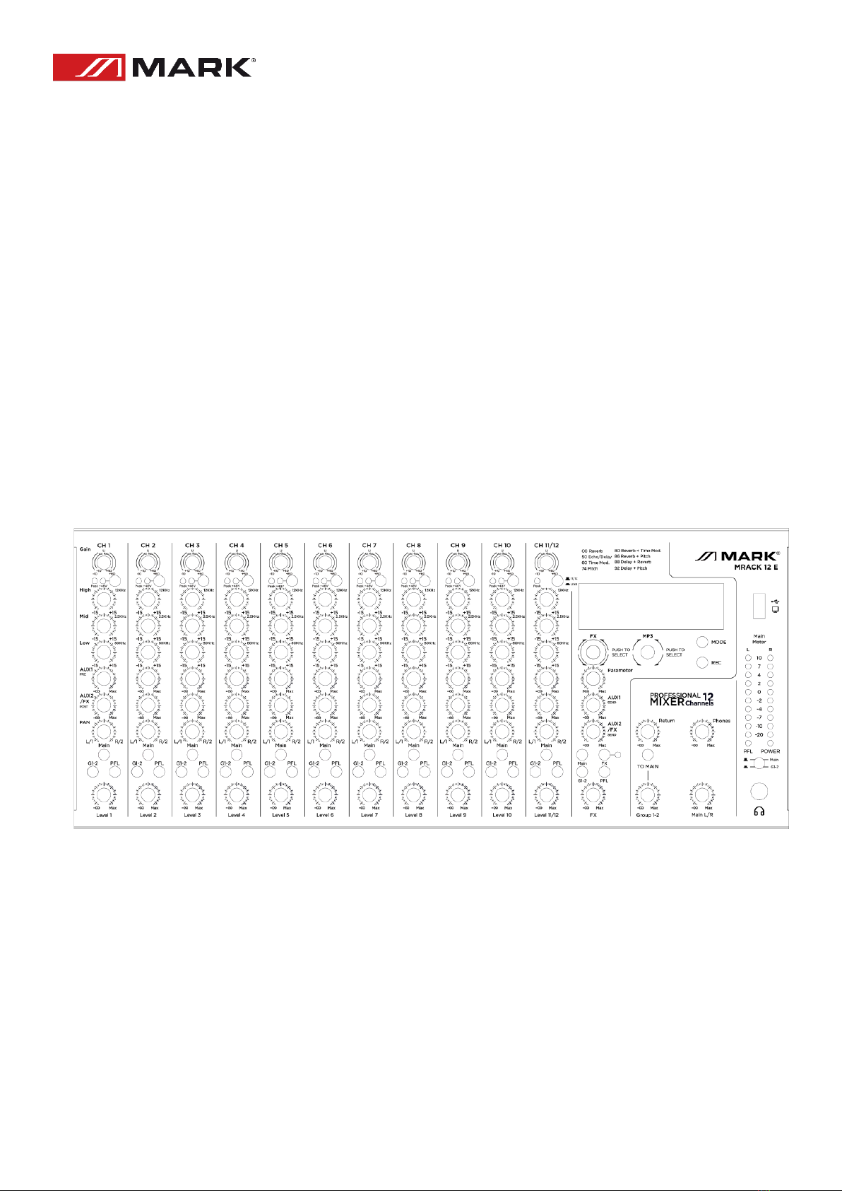
OVERVIEW
MRACK 12E is an analog 12 Channel, 10 mono + 1 stereo, Rackmount Mixer. with 3 tone controls per channel and
send/return connections.
The input mono channels of the MRACK 12E MIC/LINE mixer incorporate phantom power for condenser
microphones.
-MRACK 12E has 2 AUX outputs (AUX1 & AUX2/EX), 2 GROUPS and foot switch connection.
MRACK 12E features a USB player/recorder and 99 built-in digital effects, Bluetooth and USB sound card
operation and 99 built-in digital effects.
Technical Data:
INPUT channels
10 mono MIC/LINE + 1 stereo
OUTPUT channels
2 Main out, Phones, 2 AUX send and 2 GROUP OUT (incl. FX)
EQUALIZATION
High
Gain: ±15dB Frequency: 12kHz
Mid
Gain: ±15dB Frequency: 2.5kHz
Low
Gain: ±15dB Frequency: 80Hz
PEAK LED
LED turns on when post EQ signal reaches 3 dB below clipping level
Level Meter
Pre Monitor LEVEL 2x10-segment LED meter (+10, +7, +4, +2, 0, -2, -4, -7, -
10, -20dB)
Built-in Effect
99 programs, 1 Parameter Control, Foot Switch
USB Player/Recorder
MP3 & WMA
Phantom Power
Voltage
48V
Main supply
AC 100 -240 V 50/60 Hz
Dimmensions (W,H,D)
483 x 85 x 208 mm
Features:
-Audio mixer with 10 mono MIC/LINE channels + 1 stereo channel
-USB player /recorder and Bluetooth and the same USB port for PC connectivity (sound card
operation).
-+48V phantom.
-99 Effect included.
-3 tone control on each input channel.
-AUX send/return connectivity.
3
CONTROLS & FUNCTIONS
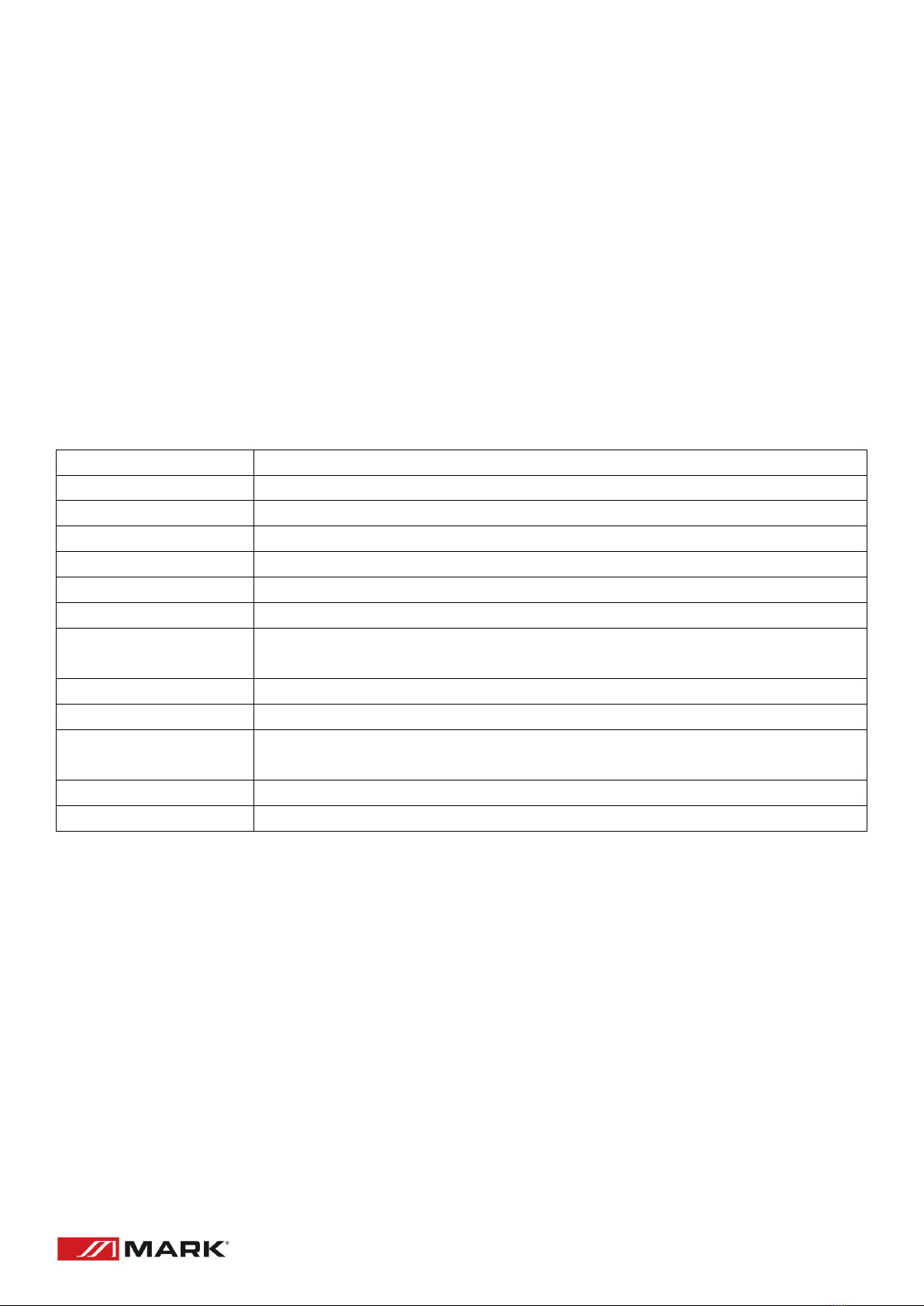
INPUT CHANNEL (MONO & STEREO)
1. MIC/LINE INPUT
Accepts both XLR and TRS connectors.
Connect the microphone or instrument you
intent to use.
+ 48V phantom power available on each
input Mic socket.
2. Stereo input jacks
These line stereo input jacks (unbalanced) for
connecting line-level instruments, such as
electric keyborads and audio equipment.
3. GAIN knob
For adjust the gain of the input signal. To get
the best balance between SNR and dynamic
range, adjust the gain so that the PEAK
indicator lights up only occasionally and briefly
on the highest input transients.
4. PHANTOM +48V switch and indicator
Turn this switch on to supply DC +48V to the
XLR input.
Be sure to leave this switch off if you don’t
need phantom power
5. PEAK indicator
The peak level of the post-EQ signal is
detected, and the PEAK indicator lights yellow
when the level reaches 3dB bellow clipping.
6. Stereo INPUT and MP3 player signal
switching
Push this switch up, the signal is switched to
stereo input (CH11/12), push this switch down
the signal switches to USB.
7. Equalizer (HIGH, MID and LOW)
Setting the knob to the middle position
produces a flat response. Turning the knob to
the right amplifies the corresponding
Frequency band, while turning to the left
attenuates the band.

4
8. AUX1 and AUX(2/FX)
AUX1 knob controls the signal level sent from this channel to AUX1 BUS.
AUX(2/FX) knob controls the adjust of signal level sent to the AUX bus and FX BUS (built-in in effects).
The same signal level is sending to the AUX and FX buses connected to these knobs.
9. PAN knobs
This knob adjusts the volume balance of each channel sent to the MAIN BUS. If the BUS assign switch
(1-2) is pressed, this knob adjusts the volume balance sent to the GROUP BUS.
10. MAIN switch
Turn this switch on assigns the channel’s signal to the MAIN BUS.
11. G(1-2) switch
Assigns the channel’s signal to the GROUP 1-2 BUSES.
12. PFL switch
When the PFL switch is on the channel pre-knob signal is output to PHONES jack for monitoring.
When a PFL switch is turned on the PFL indicator below the level meter flashes.
13. Channel knobs
For adjusting the level of the channel signal. Use this controls to adjust the balance between the
various channels.
5
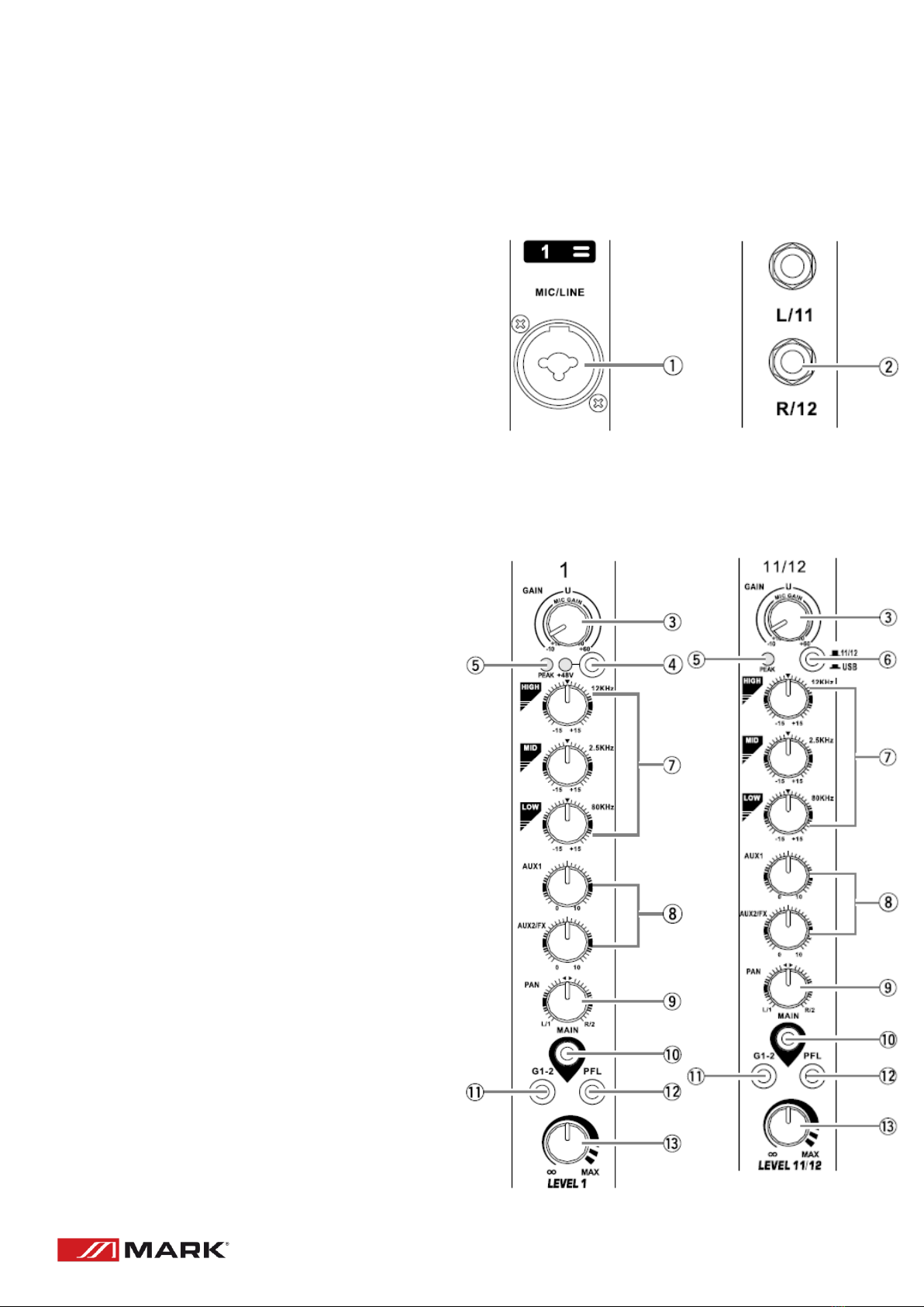
MASTER BLOCK
1. MAIN OUT
These are XLR and TRS balanced output that
output the mixed stereo signal.
2. GROUP OUT jacks
These impedance-balanced TRS output the
(GROUP 1-2) signals. Use those jacks to
connect to the input of a multi-track recorder,
external mixer, or another similar device.
3. AUX jacks
AUX (1-2) are impedance-balanced TRS, these
jacks output signals from AUX. You use these
jacks, for example, to connect to an external
effect device.
4. RETURN
These are unbalanced jacks. Signal received
by these jacks is sent to the MAIN BUS.
These jacks are typically use to receive return
from an external effect device (reverb, delay…)
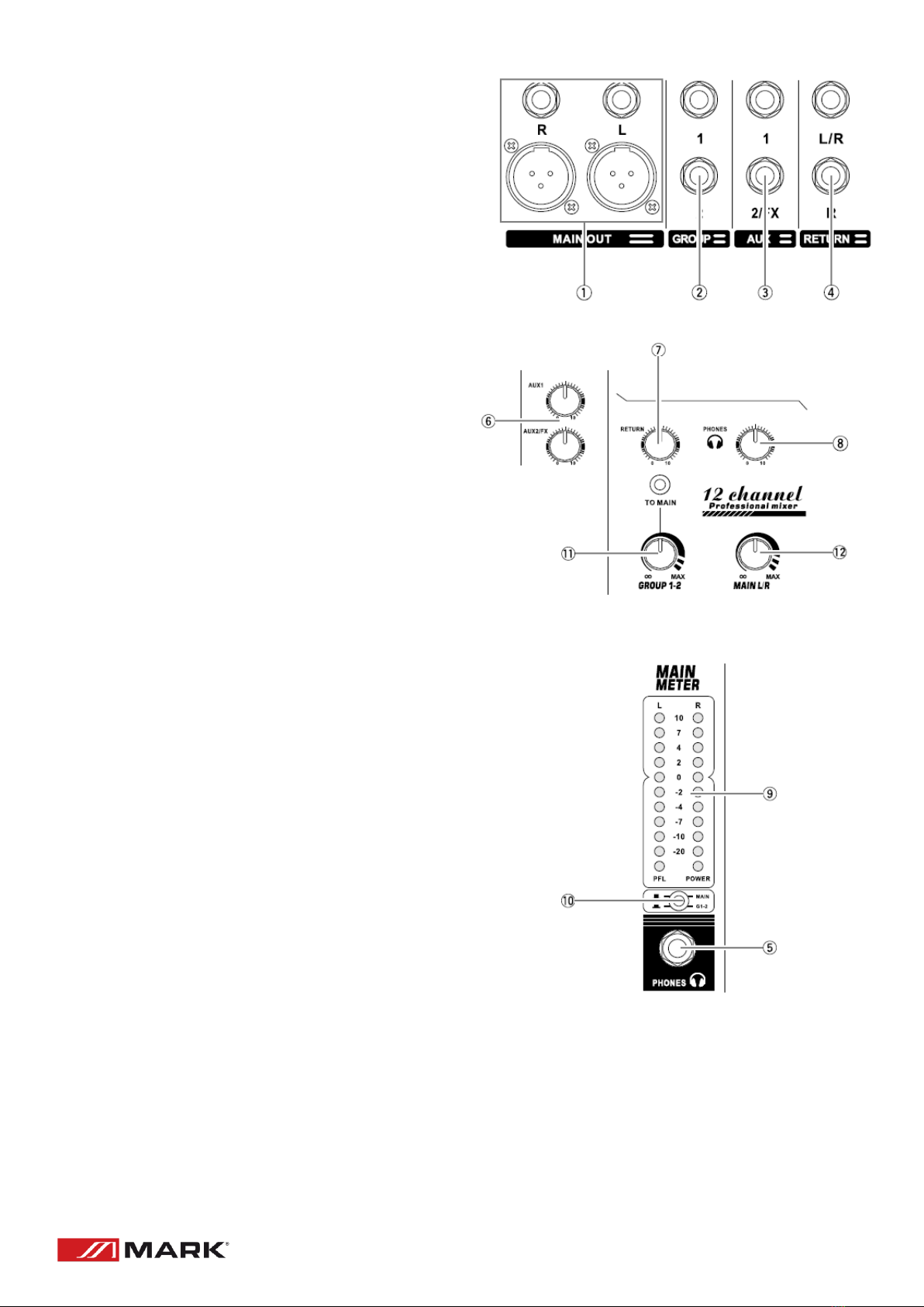
5. PHONES jack
Connect a pair of headphones to this TRS
phone jack.
6. SEND knob AUX(1-2)
For adjusting the level of the signals output to
the SEND jack and AUX(1-2).
7. RETURN knob
For adjusting the level of the signals sent
from the RETURN input jack to the stereo
BUS.
8. PHONES knob
For adjusting the level of the signals output to the phones.
9. POWER level control
The level meter LED shows the level of the signal in the MAIN and GROUP buses or selected PFL
channel.
6
10. MAIN(G1/G2)
This switch can switch the output signal of MAIN or GROUP to PHONES.
11. GROUP knob
-(GROUP 1-2) knob. For adjusting the level of the signals output to the (GROUP OUT 1,2) jacks.
-(TO MAIN) switch. If it is on, the signals are sent to the MAIN BUS via the (GROUP 1-2) knob.
12. MAIN(L-R)
For adjusting the level of the signals output to the MAIN OUT jack.
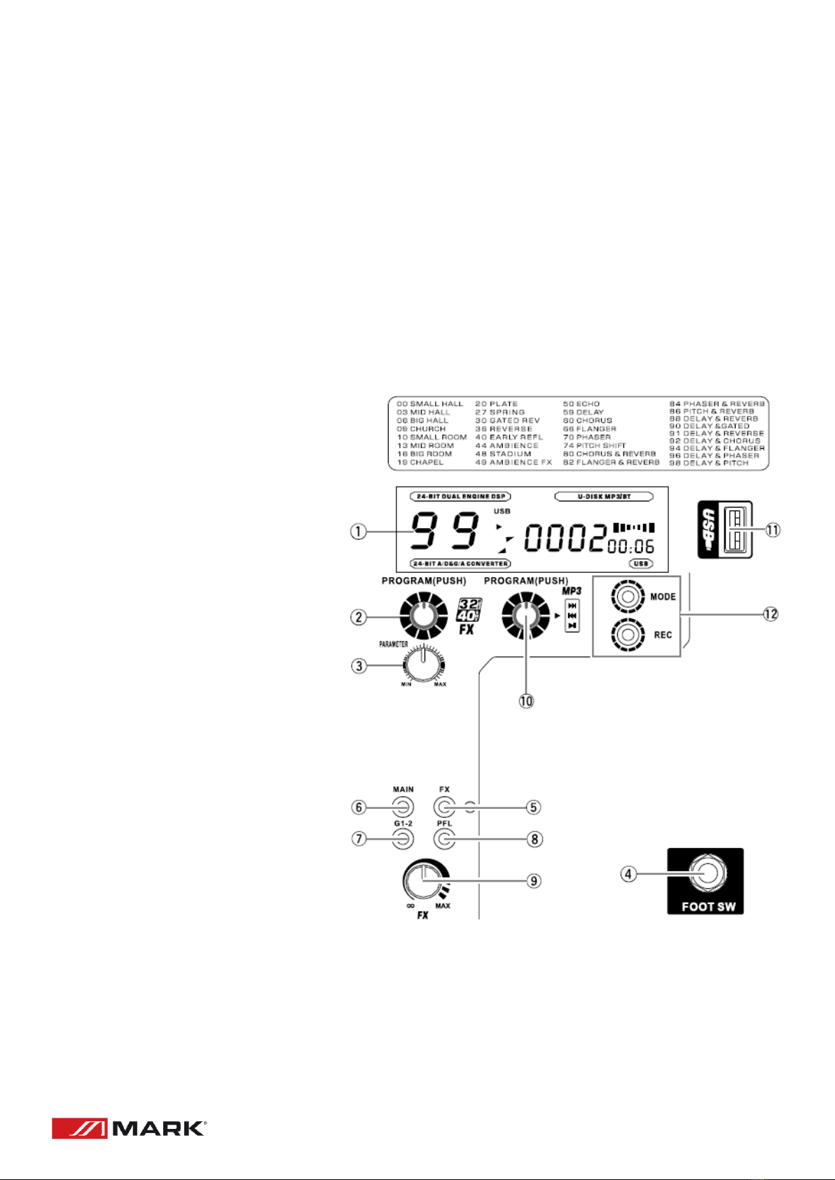
BUILT-IN EFFECTS AND MP3 BLOCK
1. DISPLAY
2. PROGRAM knob
To select an effect turn the knob
and press the knob to enable it.
3. PARAMETER knob
For adjusting (depth, speed…) for
the selected effect. The last value
used with each effect type is
saved.
4. FOOT SW jack
Connect a foot switch to this
input jack.
5. FX switch
This button turns the
corresponding effect on or off.
When the fuction is ON the
switch lights red.
6. MAIN switch
Turn this switch on to output the
signals of the built-in effect to
the MAIN buses.
7. G1-2 switch
Turns this switch on to output signals of the built-in effect to the GROUP 1-2 buses.
8. PFL switch
To output the built-in effect signals to the PFL buses, turn this switch on.

7
9. FX knob
For adjusting the level of the effect sent from to built-in effect to the GROUP 1-2 and MAIN
buses.
10. PROGRAM mp3 KNOB
Turn the knob to select the desire music file, press the knob to play/pause/record/confirm the
selection.
11. USB player
Insert a USB flash drive with music files such as MP3, WMA into the player’s jack and control the
playback of the music trough the PROGRAM knob.
12. MODE and REC button
This player has a Bluetooth and recording function. Use MODE button to switching. Press the
REC button after inserting the USB flash drive, an then press the “confirm” button to record. The
recording content is the main output signal. Long press program knob to stop recording.
After recording, press the MODE button to switch to USB MODE or Bluetooth MODE, and pull
out USB disk.
13. USB Section
USB 2.0 port type A
Connects to a computer via a USB cable. The signal from the MAIN L/R buses is output to the
computer.
CAUTIONS:
Use an A/A type USB cable. The cable should be no more than 1.5 m long. An USB 3.0 cable
cannot be used.
Be sure the computer is not in sleep/suspend/standby mode before making a connection with
the mixer.
Connect the mixer to the computer before turning the mixer power on.
8
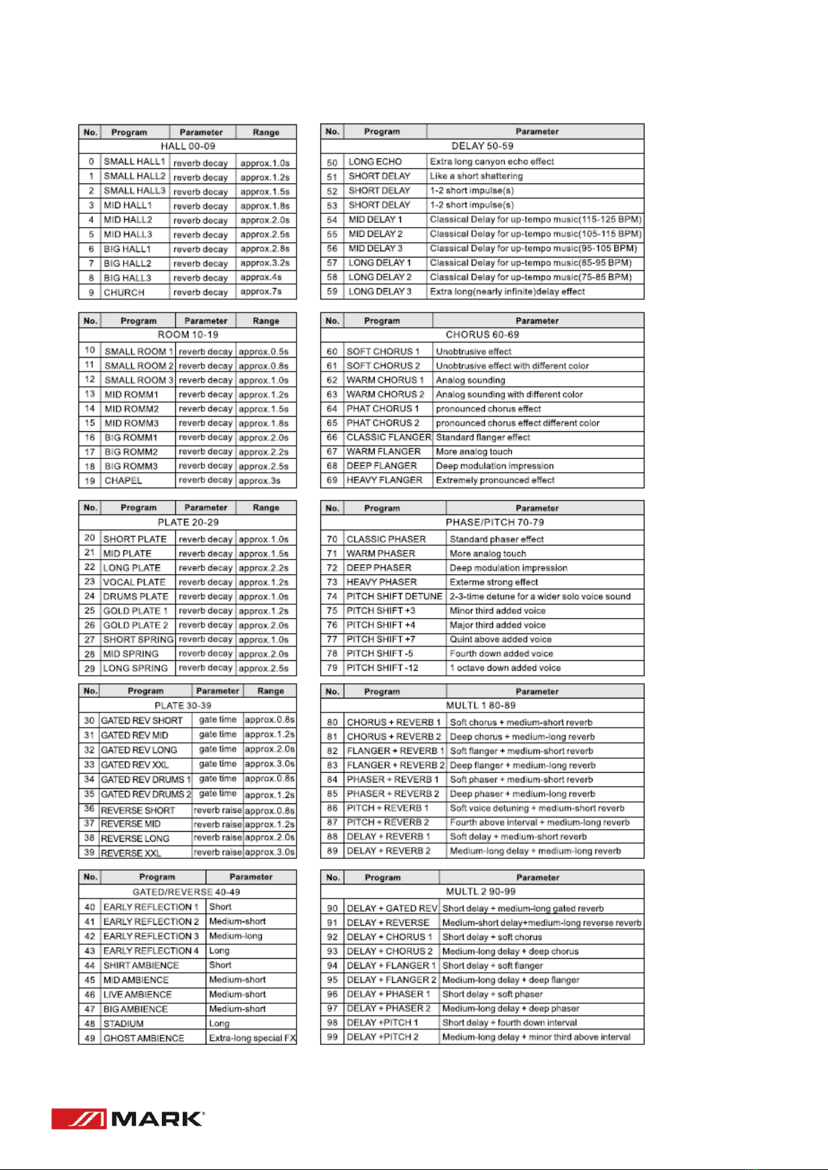
BUILT-IN EFFECT PROGRAMS
9
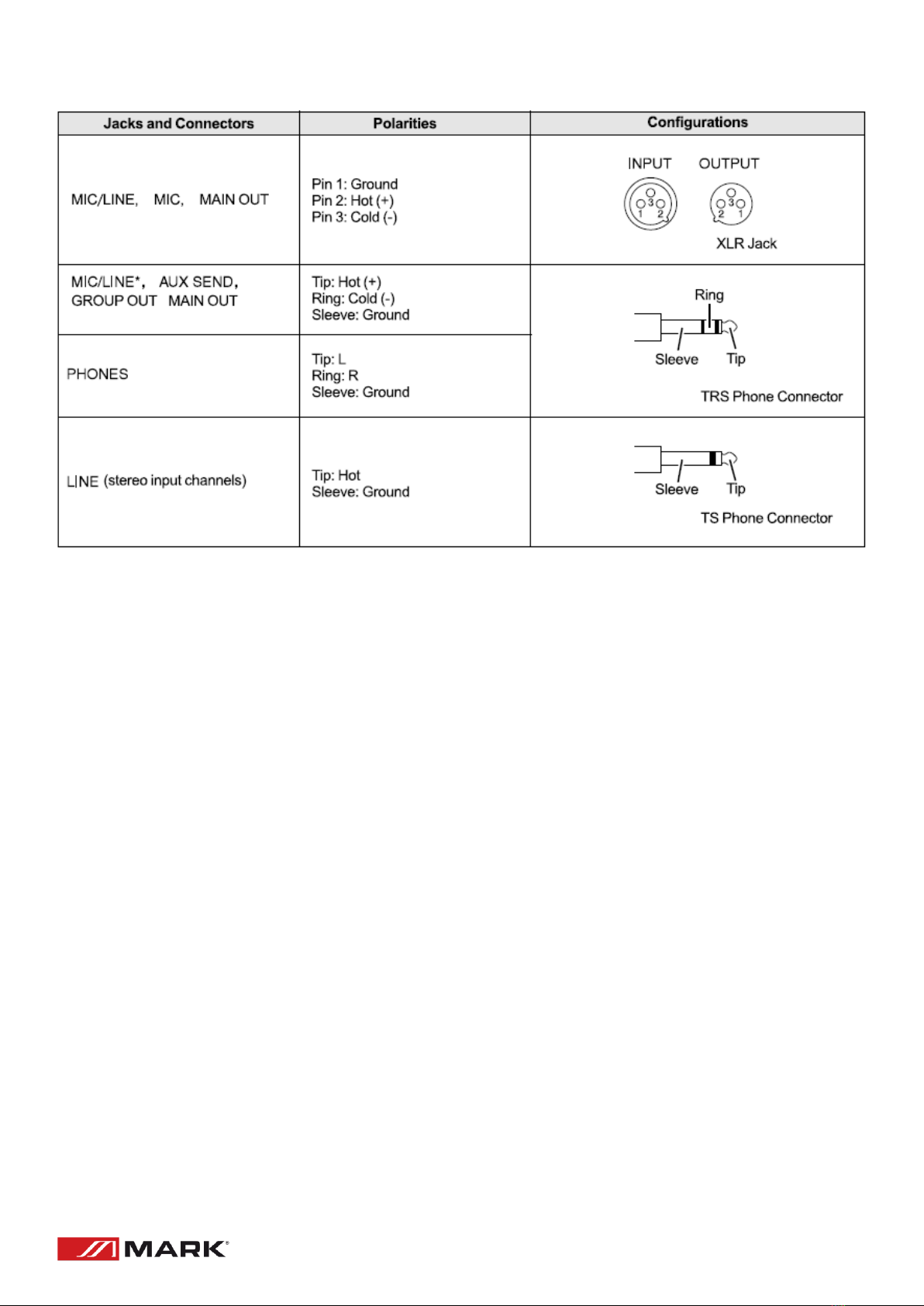
JACK AND CONNECTOR LIST
Table of contents
Languages:
Other Mark Dj Equipment manuals

Mark
Mark BEAM LED 150 User manual

Mark
Mark DecoPAR DPR36 User manual

Mark
Mark BEAM 350 User manual

Mark
Mark BEAM 190 User manual

Mark
Mark BEAM 198 MKII User manual

Mark
Mark THEATRE 650 User manual

Mark
Mark Superparled 355 IP User manual

Mark
Mark MOVILIGHT BEAM 150 User manual

Mark
Mark DecoPAR DPR30 User manual

Mark
Mark SUPERPARLED 136 User manual


