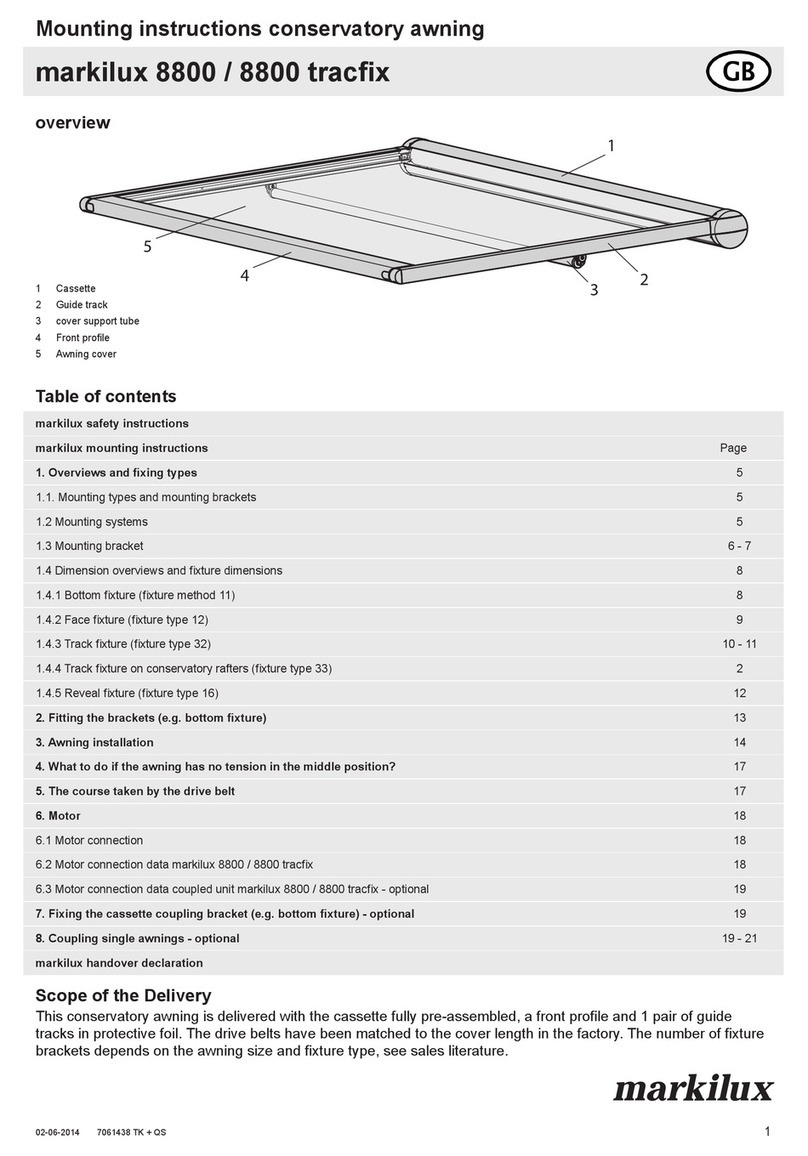
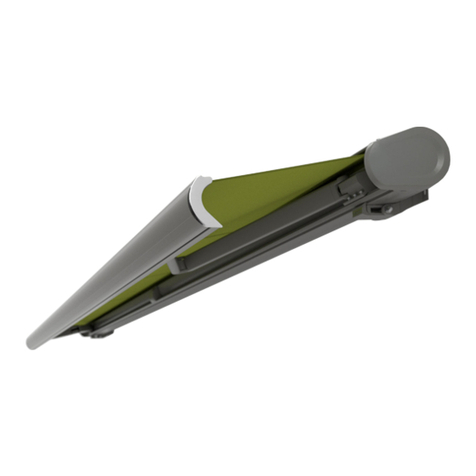
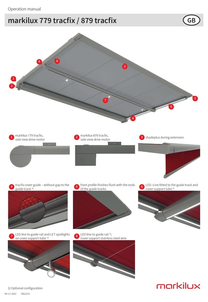
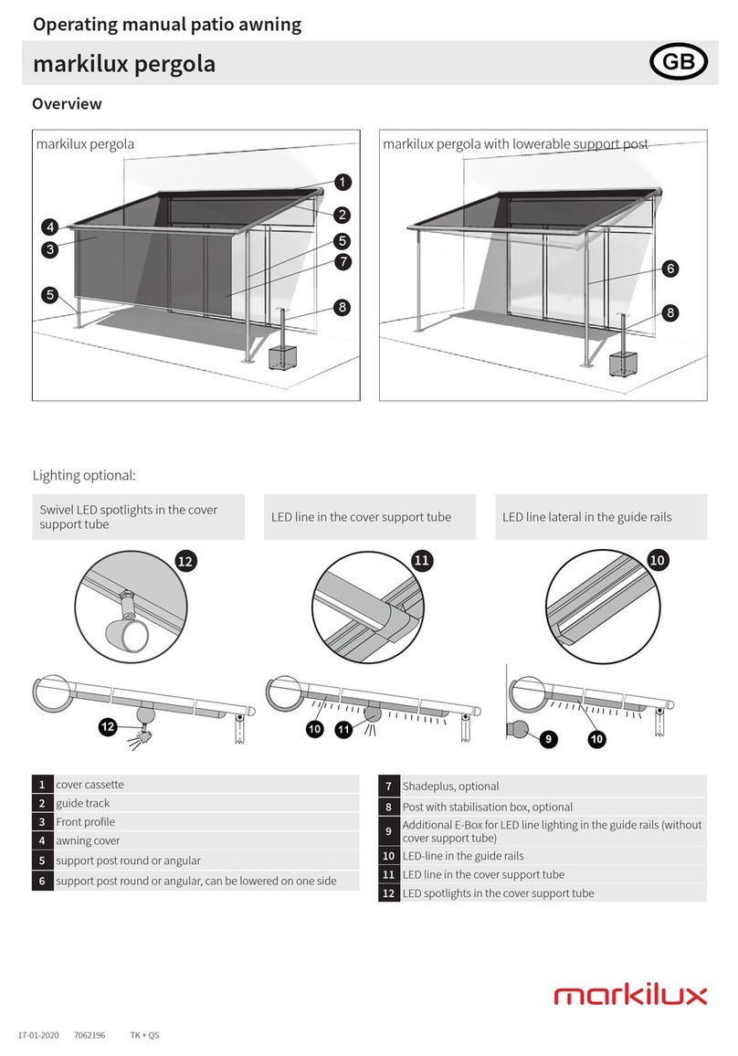
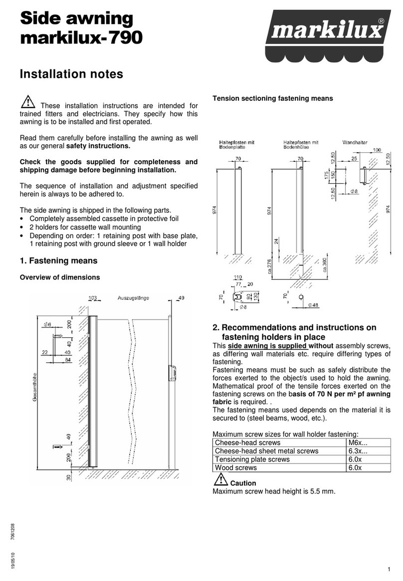
Markilux pergola 110 User manual

safe • timeless • beautiful
Conservatory awnings − shade for large areas
markilux 8800 | pergola 110 / 210 | pavillon
markilux
20-04-2015 7060488 TK + QS
What to to do, if... Page
1. … the cassette cover has to be removed? 2
2. … the tension on the cloth has to be released? 2
3. … the drive belt in the guide rail is twisted? 3
4. … the drive belt has to be wound around the roller tube again?
− Application of the drive belt assembly tool 4
5. … the awning does not retract/extend or the motor limit switch is wrongly adjusted? 4
6. … the awning stops approx. 10 - 15 cm prior to retraction position? 4
7. … the projection profile stops before reaching the end stop in extension direction? 5
8. ... the awning has no tension on one side? 6
9. ... the awning has no tension in the middle position? 7
10. … the awning runs unevenly? 7
11. … the Velcro fastener / drive belt has been pulled out of the belt clamp in the projection prole? 7
12. … the awning cloth should be replaced? 8
13. … the projection profile cap (with carriage) should be replaced? 9
14. … the motor should be replaced? 10
15. … the drive belt needs to be replaced? 11
16. … the projection prole does not retract completely on one side? 12
17. … maintenance is required? 12
18. Motor overview 13
19. Brief instructions for "Becker" drive with electronic limit switch (standard motor without radio) 14
20. Important general guideline for this "What do I do, if, ...?" booklet 17
What to to do, if...
This booklet describes in simple words the necessary
assembly steps in case any problems occur.
Table of contents
markilux 8800
markilux pergola 110 / 210
markilux pavilion
The work described here may only be carried out by a trained
markilux specialist company.
www.samsondoors.co.uk
0800 328 6250
www.samsondoors.co.uk
0800 328 6250
www.samsondoors.co.uk

2
www.markilux.com
1. … if the cassette cover has to be removed?
8
9
41
Unscrew the countersunk screw (8) on the side cover and remove the
inspection cap (9). Remove the cassette lid (41).
2. … if the tension on the cloth has to be released?
e.g. in case of motor and cloth replacement or maintenance work
19
23 2
By pulling the drive belt (19) out of
the guide rail (2) in the direction of
the middle of the awning, release
the tension on the clamping module
and fix it using a safety splint (23)
into the guide rail (right and left).
Possibility A: Retracted or partially retracted awning.
Possibility B: Completely extended awning.
NOTE: If the cloth should be
reclamped, pull out the safety splint
(23) by releasing the tension on the
clamping module again, see also
Chapter 3, Point 4.
Depending on the system size, one or two storm chocks (40) are positioned
at the rear between the lower cassette (5) and the cassette cover (41),
which need to be removed.
Once the cassette lid (41) has been reinstalled, the safeguards (40) are
reinserted.
41
40
5
1. Remove the cap closure (21) and
remove the drive belt (19) from the
projection prole (right and left).
3. Hold the drive belt (19) tight with
one hand, thus securing it.
Press the belt clamp (29) and release
the drive belt (19) carefully a little
way at a time until there is no more
tension on the clamping module.
21 29
19
10 cm
19 29
Attention! Hold the belt tightly
at the loose end when the system
is under tension and the belt
clamp is pressed!
NOTE: If the cloth should be
reclamped, proceed acc. Chapter
7., Points 5. and 6.
www.samsondoors.co.uk
0800 328 6250
www.samsondoors.co.uk
0800 328 6250
www.samsondoors.co.uk

3
www.markilux.com
NOTE: See also Figure Chapter 15. Drive belt progression
3. … if the drive belt in the guide rail is twisted?
20
13
18 5
13
13
19
5Cassette
13 Belt roller
18 roller tube
19 Drive belt
20 front prole
21 29
19
1. Release the tension on the awning
cloth as described in Chapter 2 by
fixing the clamping module with the
safety splint (23) (right and left).
Open the inspection cap (see
Chapter 1). Remove the cap closure
(21) of the projection profile, remove
the drive belt (19).
2. Withdraw the connected Velcro
fastener (22) with the drive belt (19) a
little way through the belt clamp (29)
of the projection profile.
Remove the twist in the drive belt :
With your fingers, push out the twist
through the belt clamp (29).
19 29
22
19 22 20
23
219
3. Carefully pull the drive belt (19)
back into the projection prole (right
and left) (20) with the aid of the
Velcro fastener (22) through the belt
clamp (29). Here the belt drive must
be held under light counter-tension.
Avoid forceful and sudden pulling.
Store the loose end of the drive belt
incl. Velcro fastener under the cap
closure (21), but do not cut it off!
4. By pulling the drive belt (19) in the
guide rail (2) in the direction of the
middle of the awning, release the
tension on the inside clamping
module so that the splint (23) can be
pulled out easily (right and left). The
awning is now under tension.
5
18
13
20
13 19 13
5
18
13
20 13 19 13
5
18
19
20
www.samsondoors.co.uk
0800 328 6250
www.samsondoors.co.uk
0800 328 6250
www.samsondoors.co.uk

4
www.markilux.com
4. … the belt has to be wound around the roller tube again?
− Using the drive belt assembly tool
1. Extend the awning by max. ¾
rotation until the roller tube groove
(27) becomes accessible. Guide the
assembly tool (17) with the thickened
end pointing upwards between the
roller tube (18) and the cassette.
17
18 12
27
12
18 17
12
17
12 17
18 19
2. Guide the drive belt clamping loop
(12) upwards.
3. Press the drive belt clamping loop
(12) through the slit in the assembly
tool (17).
Attention! Do not twist the drive
belts!
4. Retract the assembly tool (17). In
this way, the drive belt (19) is wound
around the roller tube (18). Remove
the drive belt clamping loop (12) from
the assembly tool.
5. Now guide the drive belt (19) a
second time around the roller tube
and insert under the first winding of
the drive belt in the roller tube groove
(27).
19
12
27
5. … the awning does not retract/extend or the motor limit switch is wrongly
adjusted?
Possibility A Possibility B
Check the awning controls and the sun/wind and rain
mechanisms and readjust if necessary.
Readjust the motor end positions. See brief instructions
for the "Becker" standard motor in Chapter 19.
6. … the awning stops approx. 10 - 15 cm prior to entry position?
Extend awning approx. 30 cm.
By pressing the belt clamp (29) alternately on the right and left side, release
the tension on the clamping module by letting more belt run through.
Release the tension on each belt bit by bit and check progress by retracting
the awning again slowly until it closes again.
Carefully extend the awning by 30
cm.
Relieve the tension on the cloth as
described in Chapter 2 (right and
left).
By pressing the belt clamps on the
right and left-hand sides (29), the
drive belts can be pulled approx. 30
cm in the direction of the guide rails.
Remove the drive belts from the
roller tube. Retract the awning.
Now proceed as in Chapter 4.!
29
Possibility A: Clamping module overtightened
Attention!
Hold the belt tightly on the loose
end; the system is under tension!
Possibility B: The belt has no
additional winding on the roller
tube
www.samsondoors.co.uk
0800 328 6250
www.samsondoors.co.uk
0800 328 6250
www.samsondoors.co.uk

5
www.markilux.com
Different cover thickness leads to different winding behaviour, which can inuence the gas piston and lead to the
projection prole stopping prior to reaching the end stop point.
NOTE: During the initial retraction and extension of systems with a projection exceeding 5 m, a tighter winding of
the cover onto the roller tube might occur. This may lead to a decrease in cloth tension or to a lower clamping
module tension. See Chapter 9.
7. … the projection prole stops prior to reaching the end stop point??
1. Extend the awning as far as
possible.
2. Remove the cap closure (21) and
remove the drive belt (19) from the
projection prole (right and left).
3. Hold the drive belt (19) tight with
one hand, thus securing it.
Attention! Hold the loose end
of the belt tightly as the system is
under tension! Press the belt clamp
(29) and the drive belt (19) and
release the tension by approx. 10
cm. Let go of the belt clamp (29)
(right and left)
21 29
19
10 cm
19 29
4. Extend the awning completely. 5. Pull the drive belt (19) on the
projection prole until it cannot be
pulled any further.
6. Now pull the drive belt (19) tight
again with one hand, and keep it in
this position, thus securing it. Press
the belt clamp (29) with your other
hand and relieve the tension on the
drive belt (19) for about 6 cm.
Release the belt clamp (29).
Check retraction and extension of the
system.
19
6 cm
19 29
7. If the projection prole does not close properly or if the awning is not tensioned uniformly, continue with Chapter
9 or Chapter 4 (Point 5).
In this case extra drive belt has to be allocated both right and left.
www.samsondoors.co.uk
0800 328 6250
www.samsondoors.co.uk
0800 328 6250
www.samsondoors.co.uk

6
www.markilux.com
5
18
19
20
8. ...the awning has no tension in the middle position?
Possibility A Possibility B
The drive belt has been partially
released from the belt clamp (29).
The drive belt has released itself
completely from the belt clamp (29).
Possibility C
Clamping module defective – request
replacement element, stating the
serial number.
• Release the tension on the
clamping module as described in
Chapter 2.
• Then correct as described in
Chapter 3.
Please refer to chapter 11.
1. Retract the connected Velcro
fastener (22) with the drive belt (19)
through the belt clamp (29) of the
projection profile.
2. Remove the guide rail cover (44)
by loosening the fillister head self-
tapping screw (43) and removing the
clamping module (38) from the guide
rail (2). To do this, unscrew the
countersunk screw M 5 (42) at the
side of the holder for the gas pressu-
re spring (45).
3. Retract the available drive belt (19)
back into the guide rail again and
thread into the clamping module.
Ensure central position and no
twisting of the drive belts (19) on the
deflection rollers.
4. Install a new clamping module into
the guide rail.
5. Retract the drive belt back into the
drive belt clamp and clamp the
awning (see Chapter 3., from Point
3.)
19 29
22
44
45 42
243
Fig.: Drive belt progression with clamping
module, right and left
www.samsondoors.co.uk
0800 328 6250
www.samsondoors.co.uk
0800 328 6250
www.samsondoors.co.uk

7
www.markilux.com
11. … the Velcro fastener / drive belt has been pulled out of the belt clamp in the
projection prole?
The awning is still in delivery condition and the cloth is not under tension.
10. … the awning runs unevenly?
Possibility A Possibility B
Are the guide rails mounted straight?
Are the guide rails perpendicular to
the cassette? Are the cassette and
guide rails positioned at right angles
to each other?
Are the guide rails dirty (leaves etc.)?
Possibility C
Are the gas pressure springs evenly
prestressed?
Align the awning at the mounting
brackets so that smooth running of
the projection profile in the guide
rails is guaranteed.
Clean the inside guide rails and
polish if necessary, see also care and
maintenance in the operating
instructions.
If not, proceed as in Chapter 8.
Possibility A.
1. Remove the cap closure (21).
2. Remove the belt clamp with the
belt clamp holder (46). To do this,
loosen the socket head cap screw
with hexagon socket, key width 6
(39).
3. Grip the drive belt and the Velcro
fastener and carefully thread it
through the projection profile (2)
and through the dismantled belt
clamp holder (46).
Note: Should the Velcro fastener
be damaged or torn off, then
thread the end of the drive belt
(without the Velcro fastener)
directly through the belt clamp
holder (46). If necessary, the
Velcro fastener can also be
retightened with staples.
4. Mount the belt clamp holder (46)
back into the projection profile (2)
and apply the cap closure.
46
39
21
2
9. … the awning has no tension in the middle position?
19 23 Retract awning.
By pulling the drive belt (19) in the guide rail (2) towards the centre, bring
the hole in the clamping module into line with that of the guide rail (right and
left). Then insert the safety splint (23) (right and left). The drive belts (19) are
now no longer under tension and the clamping module is held securely in
position. Now tighten the drive belts (19) as described in Chapter 2 and
tension the awning again.
www.samsondoors.co.uk
0800 328 6250
www.samsondoors.co.uk
0800 328 6250
www.samsondoors.co.uk

8
www.markilux.com
12. … the awning cloth has to be replaced?
Order the cloth, stating the serial number.
1. Remove the inspection cap (9),
and release the tension on the cloth
(see Chapter 2.)
8
9
41
4. Disconnect the motor mains
connection via the plug coupling in
order to prevent extension or
retraction of the system whilst the
work is being conducted.
2. Remove the drive belt clamping
loop (12) from the roller tube groove
(27).
3. Extend the awning by approx. 20
- 30 cm.
12 27
20 - 30 cm
5. Remove the guide rails (2) on both
sides. To do this, unscrew the socket
head cap screws, key width 6 (16)
from the rail by 15 mm, and loosen it
by lightly tapping the connection on
the screw head!
Remove the guide rail (2) so that the
projection profile lies exposed at the
side.
6. Remove the cloth dowelling pins
(30) and the piping (31) from the
projection profile groove.
Attention!
In case of awnings with tracfix
system, first release the additional
screws (32) of the tracfix terminal on
the carriage.
8. Activate the motor via the
adjustment set (for standard motor,
see also Chapter 19) and extend the
awning until the cloth (3) is
completely unwound from the tube.
Pull out the cloth dowelling pins (32)
and the piping (31) via the roller tube
groove (27).
Clean the roller tube, cassette and
projection profile after inserting a new
cloth!
16 25
32
31
30
32 31 27 3
NOTE: To make the work easier, the roller tube and the projection profile can also be removed and the cloth
changed by resting it on trestles.
5. Loosen the cassette housing (2)
on both sides. To do this, unscrew
the socket head cap screw, key width
6 (16) from the rail by 15 mm and
loosen the connection by lightly
tapping on the screw head!
Remove the cassette (2) so that the
projection profile is exposed at the
side.
16 25
7. Reconnect the motor power
connection.
A: In case of cassette floor and
wall assembly B: For cassette frame assembly
www.samsondoors.co.uk
0800 328 6250
www.samsondoors.co.uk
0800 328 6250
www.samsondoors.co.uk

9
www.markilux.com
10. Insert the clamping loops (12) of
the drive belts (19) with the awning
retracted back into the roller tube
(18) (see Chapter 4).
Then tension the awning cloth as
described in Chapter 3. Point 4.
19
12
27
9. Insert the cloth (3) into the lower
piping groove of the projection
profile, and thread in the piping (31).
Carefully lay the cloth over the
projection profile. With a rounded,
thin sheet metal plate (37), prefold
the cloth into the upper piping run
and then draw in the upper piping.
Only fix the lower piping, and
therefore also the cloth with the cloth
dowelling pins (30) at the right and
left-hand sides again.
11. Reprogram the end positions of
the motor with the adjustment set (in
case of "Becker" standard motor),
see Chapter 18.
37
31 30
3
13. … the projection prole cap (with carriage) has to be replaced?
5. Fasten the belt clamp holder (46)
again with the socket head cap screw
with hexagon socket, key width 6
(39). Reapply the cap closure (21).
46
39
21
2
2. Remove the cap closure (21) on
the respective belt clamp of the
projection profile (2). Deinstall the
belt clamp with the belt clamp holder
(46). To do this, loosen the socket
head cap screw with the hexagon
socket, key width 9 (39). Remove the
drive belt from the carriage.
3. Behind the previously-loosened
socket head cap screw (39) there is
a threaded pin M 5 (47). Loosen the
threaded pin.
4. Remove the old carriage. Thread
the drive belt (19) through the new
carriage (48) and the drive belt
holder (46). Tighten the threaded
screw M 5 (47), see Point 3.
Insert the new carriage (48) into the
projection profile (2).
46
39
21
2
47
48 2
19 46
1. Expose the respective carriage at the protection prole cap so that it can be accessed, see also Chapter 12
Point 1. to 5. In case of tracx systems, rst loosen the tracx terminal screws as described in Chapter 12 Point 6.
8. Apply the new cloth.
Attention! In case of awnings
with tracx system, the cloth must
be threaded into the plastic rail (15)
with the "zipper" (14) for the tracx
system to function.
Then x the cloth with the tracx
terminal and the screws (32), see
Point 6., with a front projection of
2mm on both sides back onto the
carriage, see Point 6.
Then mount the guide rail (2) onto
the side cover.
15
14
2
www.samsondoors.co.uk
0800 328 6250
www.samsondoors.co.uk
0800 328 6250
www.samsondoors.co.uk

10
www.markilux.com
14. … the motor has to be replaced?
In case of a retracted, partially or completely extended awning:
6. Replace the motor.
After installation of the new motor,
secure the motor cable again using
the previously-unscrewed inside
plastic screw (36).
4. Loosen the locking bolts, key width
5 (33) on the motor side.
5. Loosen the motor cable safeguard.
To do this, unscrew the plastic screw
for the motor cable (36) lying inside
the cassette.
Lift the roller tube (18) until the motor
(34) can be pulled out of the tube.
33
18
36
34
1. Remove the inspection cap (9),
see Chapter 1.
2. Release the tension on the cloth,
see Chapter 2.
Attention!
Secure the projection profile against
uncontrolled extension during the
deinstallation of the motor.
3. Disconnect the motor mains
connection via the plug coupling.
8
9
41 19
23 2
7. Put the system back into operation
and program the positioning of the
end positions with the adjustment
set, see Chapter 18 (standard motor
without radio).
Prior to this, order a replacement motor, stating the awning serial number.
www.samsondoors.co.uk
0800 328 6250
www.samsondoors.co.uk
0800 328 6250
www.samsondoors.co.uk

11
www.markilux.com
15. … the drive belt has to be replaced?
Prior to this, order a new drive belt including the Velcro fastener, stating the serial number.
Possibility A: The drive belt is torn
1. If the drive belt is torn, the appropriate clamping module is relieved of tension. The second drive belt must then
also be relieved of tension according to Chapter 2. Possibility B, by pressing the belt clamp.
2. On the side where the drive belt has to be replaced:
Remove the guide rail cover (44) by loosening the fillister head self-tapping screw (43) and removing the
clamping module (38) from the guide rail (2). To do this, unscrew the countersunk screw M 5 (42) at the side of
the holder for the gas pressure spring (45).
3. Remove the old drive belt (19).
4. Thread the new drive belt (19) onto the clamping module and then into the guide rail (38). Ensure central position
and correct running of the drive belts (19) on the deflection rollers.
5. Reinstall the belt clamp (29) after pulling through the drive belt (19) (see Chapter 11).
6. Fasten the drive belt clamping loop onto the roller tube, see Chapter 4.
7. Reclamp the awning, see also Chapter 3, from Point 3.
5
18
19
20
29
38
44
45 42
2
43
Fig.: Drive belt progression with clamping
module, right and left
www.samsondoors.co.uk
0800 328 6250
www.samsondoors.co.uk
0800 328 6250
www.samsondoors.co.uk

12
www.markilux.com
17. … maintenance has to be carried out?
In order to prevent malfunctions or to detect any damage early on, the product must be regularly serviced (at least
once per year).
1. Check the product regularly for signs of wear, damage to the motor line and for stability (e.g. screws for tight
fit)!
2. The required spare parts or wear parts should be ordered in advance, stating the serial number.
2. Check the cassette, guide rails and guide rail end caps for dirt, smaller branches, leaves, pine needles etc.
and clean if necessary.
3. Carry out a visual inspection and check on the holder fastening, the cloth, the drive belts and a functional
inspection of the motor limit switching.
4. Carry out a function check on the belt deflection rollers for smooth running and clean if necessary.
5. Replace damaged drive belts.
6. If the cloth is too loose during the running phases, retighten the belts in retracted condition.
7. If the connection of the projection profile is not parallel, adjust through the insertion of fabric wads on the roller
tube, see Chapter 16.
8. In case of systems with radio remote control, the battery must be replaced.
16. … the projection prole does not retract completely on one side?
(compensation possible through fabric support)
1. Delete positioning of the lower end position using the adjustment set
for the "Becker" standard motor, see Chapter 18.
2. Extend the awning until the cloth sags visibly.
3. At the awning side, which does not retract completely, push fabric strips
(approx. 20 x 20 cm) between the cloth and the roller tube so that it
cannot fall out again.
4. Retract the awning and check the position of the projection profile.
5. By supporting with smaller or larger wads of fabric, the retraction
adjustment can be adapted.
6. Position the lower end positions with the adjustment set for the
"Becker" standard motor, see Chapter 18.
Possibility B: The drive belt is torn slightly
1. Release the tension on the cloth, see Chapter 2.
2. Unthread and cut off the drive belt clamping loop (12) (see Figure under Chapter 4, Point 5) from the roller
tube groove.
3. Fasten the fleece band of the new drive belt, for example using staples, onto the old drive belt at the cut-off
point. Now, with the aid of the damaged drive belt, pull the new drive belt through the belt clamp. See Chapter
11 and also the drive belt progression Chapter 15.
4. Remove the staples and the damaged drive belt.
5. Tension the awning. See Chapter 3.
www.samsondoors.co.uk
0800 328 6250
www.samsondoors.co.uk
0800 328 6250
www.samsondoors.co.uk

13
www.markilux.com
18. Motor overview
Motor data
single unit coupled units
Torque [Nm] 40 60
Speed [rpm] 17 11
Voltage [V] 230 230
Frequency [Hz] 50 50
Current consumption [A] 1.2 1.15
Motor power [W] 246 260
Duty cycle [min] 4 4
Limit switch range [U] 64 64
single unit
With radio (433 MHz) Somfy Orea 35/17 RTS optionally
with radio IO technology (868 - 870 MHz) Somfy sunea 50 IO optionally
wired Becker R 40/17 C SE K2 without tracx
Without radio (silenteC Becker markilux AB optionally
Coupled unit
wireless (433 MHz) Somfy Orea 55/17 RTS optionally
with radio IO technology (868 - 870 MHz) Somfy sunea 60 IO optionally
wired Becker L 60/11 C SE K2 without tracx
Observe the installation and adjustment instructions. These are attached to the motor cable in case of new
deliveries, or included with the awning. In case of radio motors, a note on the adjustment of the motor at the awning
is included with new deliveries.
single unit
mit Funk (433 MHz) Somfy Orea 35/17 RTS optionally
wired Becker R 40/17 C SE K2 without tracx
Without radio (silenteC Becker markilux AB optionally
Coupled unit wireless (433 MHz) Somfy Orea 55/17 RTS optionally
wired Becker L 60/11 C SE K2 without tracx
markilux 8800
markilux pergola 110 / 210
markilux pavilion
single unit With radio (433 MHz) Somfy Orea 55/17 RTS optionally
Adjustment instructions for radio motors with 433 MHz technology
For radio motors, markilux provides the additional booklet "Adjustment instruction for radio motors with 433 MHz
technology". This booklet describes in simple words the adjustment of markilux awnings via radio, and any
problems which may occur.
Order no. German: 7061444
English: 7061446
French: 7061445
Spanish: As pdf file
www.samsondoors.co.uk
0800 328 6250
www.samsondoors.co.uk
0800 328 6250
www.samsondoors.co.uk

14
www.markilux.com
5. In addition, press the reset/programming button again.
The tube drive will make a "click-click" sound in
acknowledgement.
The end positions are now deleted.
4. Now release the reset/programming button and
continue to keep the travel button pressed.
19. Brief instructions for "Becker" drive with electronic limit switching
(standard motor without radio)
B Deletion of end positions:
1. Approach the required extension end position on the
adjustment set.
2. Press the rest/programming button on the adjustment
set. The acknowledgement was successful if the tube
drive emits one clicking sound.
If the clicking sound is heard twice, an existing end
position has been deleted! Then it is necessary to press
again until the tube drive emits one clicking sound.
3. Then RETRACT until you reach the top, permanent,
existing end stop.
The tube drive will switch off automatically. The end
positions are adjusted.
1. Move the awning between the end positions!
A Adjustment of new end positions
2. Press the reset/programming button and keep it
pressed.
3. Then press down the travel button and keep it
pressed.
www.samsondoors.co.uk
0800 328 6250
www.samsondoors.co.uk
0800 328 6250
www.samsondoors.co.uk

15
www.markilux.com
C Plug-in coupling wiring diagram "Hirschmann" for "Becker" standard motor without radio.
Plug-in coupling for "Becker" standard motor, connection line 4 x 1.5 mm²
H05RR-F 4 G 075 sw
1
2
3
1
2
3
PE
4
10
10
2
7
8
9
230 V
3 4 5
6
11
Becker drives with electronic limit switching can be
switched in parallel.
Observe the permitted maximum current carrying
capacity of the switching element.
Only qualified specialists may carry out work on the
electrical system. Electrical installations must comply
with the valid standards and regulations. During
installation, an all-pole disconnection possibility from the
mains with at least 3 mm contact opening width per pole
must be created (DIN EN 60335). Only use switching
elements with mechanical or electrical locking which
guarantee that the motor is switched voltage-free for at
least 0.5 seconds when the motor changes direction
directly.
1Neutral (blue)
2High/low command (black)
3High/low command (brown)
4PE = Protective conductor PE (green-yellow)
1Electronics
2black
3brown
4blue
5green-yellow
6Adjustment set
7Protective conductor (green-yellow)
8N (Neutral conductor, blue)
9L1 (Phase, brown or black)
10 motor
www.samsondoors.co.uk
0800 328 6250
www.samsondoors.co.uk
0800 328 6250
www.samsondoors.co.uk

16
www.markilux.com
D What to do if the end positions on a Becker standard drive cannot be
adjusted as described?
Awning extension
Awning retraction
Reset / programming button
Overview of different adjustment sets for the "Becker" standard motor
www.samsondoors.co.uk
0800 328 6250
www.samsondoors.co.uk
0800 328 6250
www.samsondoors.co.uk

17
www.markilux.com
FAULT Standard motor CAUSE REMEDY
Tube drive exceeds the end
position or does not reach the set
end position.
1. Electrical connection has short-
circuited due to humidity.
Repair electrical connection and
reset the end positions.
2. External consumers are switched
in the connection lines of the tube
drive.
Check the electrical installation,
remove external consumers, reset
end positions.
3. L1 and N connections swapped
due to long line length.
Swap L1 and N (N = bl, L1 = SW/
bn), reset end positions
4. Stops have been torn off or one
or more suspensions have been
broken.
Repair system; reset tube drive,
then reset end positions.
Tube drive does not run in the
specified direction.
1. Tube drive is overheated. After several minutes, the tube drive
is ready for operation again.
2. Tube drive defective (does not
run, even after a longer downtime).
Replace tube drive; conduct RESET
with programming button. Here you
will not hear a "click" (emergency
program), the tube drive can be
raised and lowered for deinstallation
using the adjustment set.
3. Tube drive has switched itself off
during the last run in the same
direction due to an obstruction.
Disentangle obstruction and
remove.
4. Faulty electrical connection. Check electrical connection.
Tube drive only runs for approx. 5
seconds. Tube drive is in error mode. Reset end positions, or replace tube
drive.
Tube drive switches off
automatically prior to
programming of the required 1st
end position (extension end
position).
Tube drive has detected a torque
increase.
1. Clear and overrun this position.
2. Press the reset/programming
button at this position.
This "What to do if ...?" does not replace the enclosed markilux original instructions and
the associated documents for the motors and controls. It is merely intended to promote
understanding of the product functionality.
The instructions contained in the original instructions must be adhered to and observed.
20. Important general guidelines for the "What to do if ...?
www.samsondoors.co.uk
0800 328 6250
www.samsondoors.co.uk
0800 328 6250
www.samsondoors.co.uk
This manual suits for next models
3
Table of contents
Other Markilux Accessories manuals

Markilux
Markilux markilux pergola User manual

Markilux
Markilux 779 User manual

Markilux
Markilux 740 User manual

Markilux
Markilux Markant User manual

Markilux
Markilux 1700 User manual

Markilux
Markilux Syncra uno User manual

Markilux
Markilux 869 User manual

Markilux
Markilux 990 User manual

Markilux
Markilux 6000 User manual

Markilux
Markilux 990 User manual