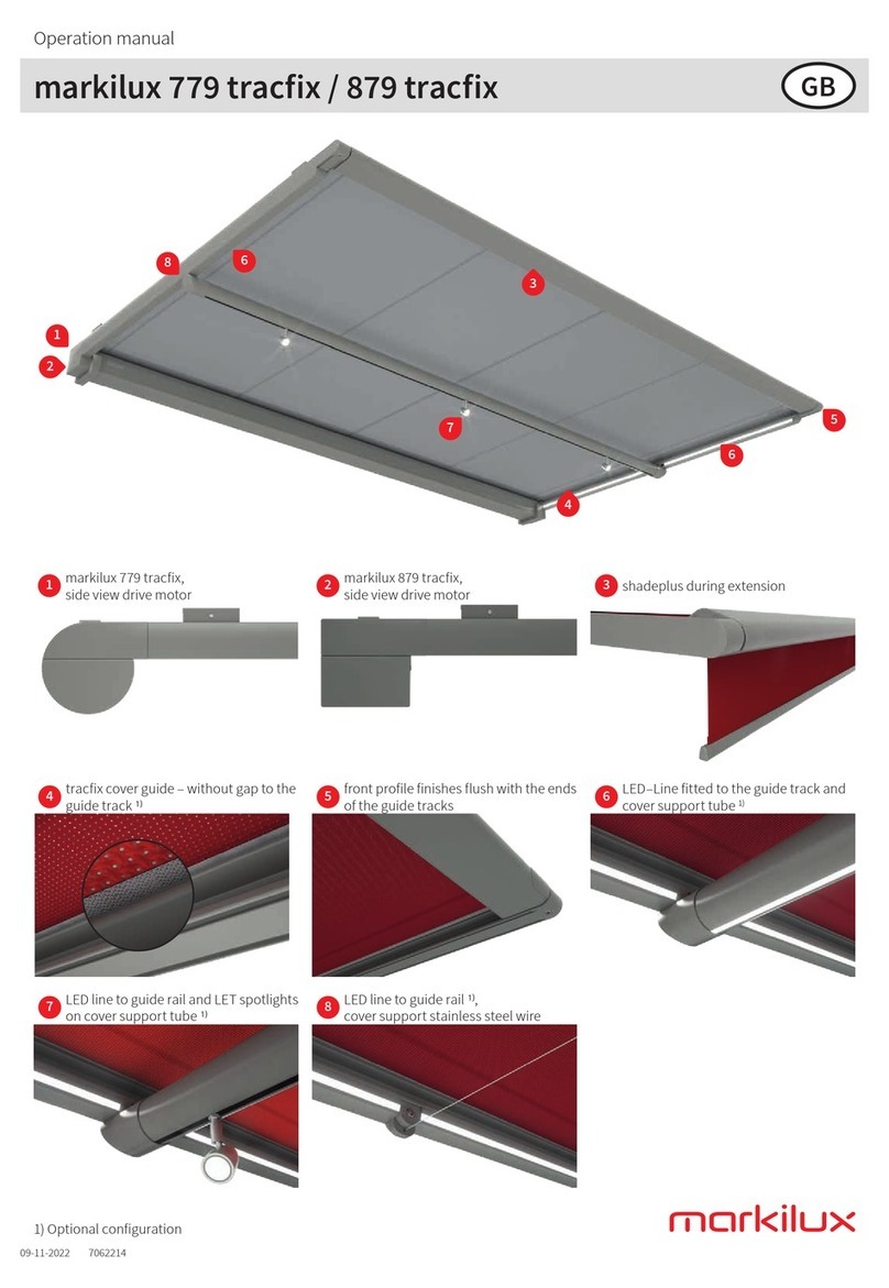
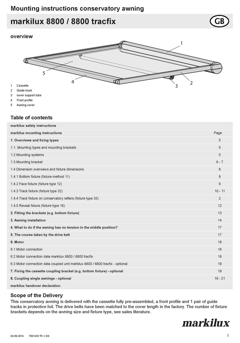
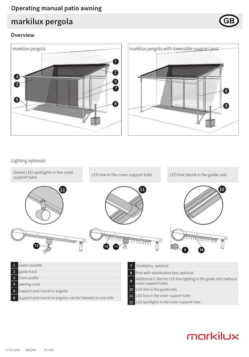
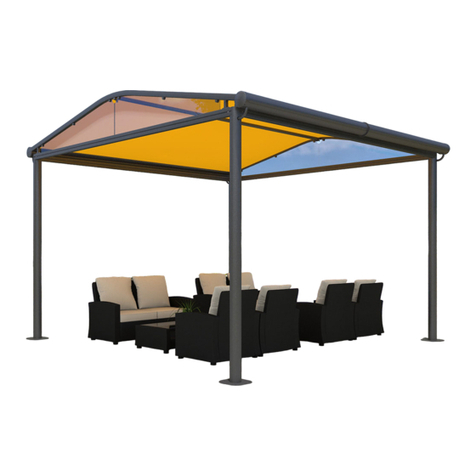
Markilux Syncra uno User manual

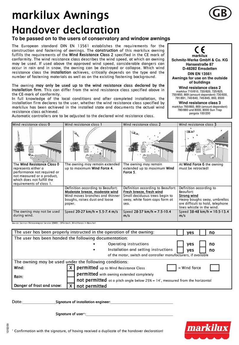
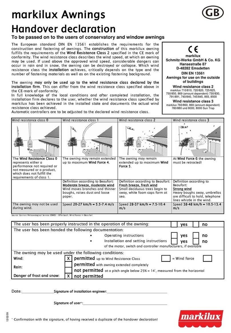
markilux Awnings
Handover declaration
To be passed on to the users of folding-arm awnings
06/04/09
Wind resistance class 0 Wind resistance class 1 Wind resistance class 2 Wind resistance class
The Wind Resistance Class 0
represents either a
performance not required or
not measured or a product,
which does not fulfill the
requirements of class 1.
The awning may remain extended
up to maximum Wind Force 4.
The awning may remain
extended up to maximum Wind
Force 5.
At Wind Force 6 the awning
must be retracted!
Definition according to Beaufort:
Moderate breeze, moderate wind
Wind moves branches and thinner
boughs, raises dust and loose
paper.
Definition according to Beaufort:
Fresh breeze, fresh wind
Small deciduous trees begin to
sway, white foam caps form at
sea.
Definition according to
Beaufort:
Strong wind
Heavy boughs sway, umbrellas
are difficult to hold, telephone
lines whistle in the wind.
The awning may not be used
during wind.
Speed 20-27 km/h = 5.5-7.4 m/s Speed 28- 7 km/h = 7.5-10.4
m/s
Speed 8-48 km/h = 10.5-1 .4
m/s
Source: German Meteorological Service (DWD) – Offenbach, Wind Forces in Beaufort
The user has been properly instructed in the operation of the awning:
yes
no
The user has been handed the following documentation:
•Operating instructions
yes
no
•Installation and setting instructions
yes
no
of the motor, switch and controller manufacturers, if available
The awning may be used under the following conditions:
Wind:
X
permitted
up to Wind Resistance Class
= Wind force
permitted
with awning extended completely
Rain:
not permitted
at a pitch angle below 25% = 14°, measured from the horizontal
Danger of frost and snow:
X
not permitted
Date
: Signature of installation engineer:
Signature of user*:
The European standard DIN EN 1 561 establishes the requirements for the
construction and fastening of awnings. The construction of this markilux awning
fulfills the requirements of the Wind Resistance Class 2
specified in the CE mark of
conformity. The wind resistance class describes the wind speed, at which an awning
may be used.
If used above the approved wind speed, considerable dangers can
occur in r
ain and in snow, the awning can be destroyed or collapse. Which wind
resistance class the installation
achieves, critically depends on the type and the
number of fastening materials as well as on the existing fastening background.
The awning may only be u
sed up to the wind resistance class declared by the
installation firm.
This can differ from the wind resistance class specified above in
the CE-mark of conformity.
In full knowledge of the local conditions and after completed installation, the
installatio
n firm declares to the user, whether the wind resistance class specified by
markilux has been achieved in the installed state and documents the actual wind
resistance class achieved.
Automatic controllers are to be adjusted to the declared wind resistance
class.
*
Confirmation with the signature, of having received a duplicate of the handover declarat
ion!
markilux
Schmitz-Werke GmbH & Co.
KG
Hansestraße 87
D-48282 Emsdetten
DIN EN 1 561
Awnings for use on the
outside of buildings
Wind resistance class 2
7061421
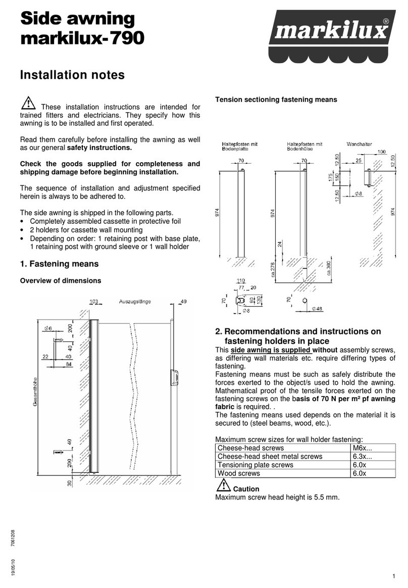
Awning stand system for a folding-arm
awning
markilux syncra uno
Mounting instructions
1
10/11/09
Table of contents
1. Overview Page 2
2. Unit's height (A ) and central posts' spacing(SAM) Page 3
3. Preparation of the transverse brace Page 4 - 6
4. Preparation of the roof elements
syncra uno with markilux 6000, 5010, 1500, 1550, skylife 2,
1200, 990
Page 7
5. Assembly of the posts Page 8
6.1.
Installation of the transverse brace
syncra uno with markilux 6000, 5010, 3300, 3300 pur,
1500, 1550, skylife 2, 1200
Page 9
6.2.
Installation of the transverse brace
syncra uno with markilux 990
Page 9
7. anging up the awnings Page 10
8. Mount frontal covering elements
syncra uno with markilux 6000, 5010, 1500, 1550, skylife 2,
1200, 990
Page 10
9. Mount covering elements
syncra uno with markilux 3300, 3300 pur
Page 11

2
1.Overview
Example: syncra uno with markilux 6000
dimensions in cm
GB =
overall width of
the unit
M
=
awning width
=
projection
A
=
unit height
D
=
headroom
SAM
=
central posts'
spacing
dimensions in cm
B = Raised-edge
stone holder
B = on-site weight-
ing via two raised-edge
stones per side (DIN
483, Form A, A4, width
15 cm, height 30 cm,
length 100 cm, weight
100 kg / piece)

3
2. Unit's height (A ) and central posts' spacing(SAM)
markilux syncra uno
with: markilux 6000 markilux 5010 markilux 3300, 3300 pur
A : 296 cm 294 cm 298 cm
SAM: M - 18 cm M - 20 cm M - 11 cm
Overall width: M M M + 3 cm
markilux syncra uno
with:
markilux 1500, 1550,
skylife 2 markilux 1200 markilux 990
A :
300 cm 299 cm 295 cm
SAM:
M - 11 cm
M - 11 cm
M - 46 cm
Overall width: M + 3 cm M + 3 cm M

4
3. Preparation of the transverse brace
Upper edge bracket (5)
must be flush with upper
edge cross beam (1)
syncra uno with markilux 6000
D = 20 mm
The distance upper edge
bracket (5) to upper edge
cross beam (1) is 12
mm.
syncra uno with markilux 5010
D = 6 mm
1
Cross beam
2
Roof bracket
3
Washer Ø 10.5
4
exagonal head
screw
M 10 x 100
5
Bracket
6
Washer Ø 13
7
exagonal head
screw
M 12 x 120
8
exagonal head
screw
M 12 x 120
9
exagonal nut M 10
10
exagonal nut M 12 Dimensions in mm

5
syncra uno with markilux 1500, 1550, skylife 2, 1200
markilux 1500, 1550,
skylife 2
D = 54 mm
markilux 1200
D = 45 mm
syncra uno with markilux 990
markilux 990
D = 7 mm
1
Cross beam
2
Roof bracket
3
Washer Ø 10.5
4
exagonal head screw M 10 x 100
5
Bracket
6
Washer Ø 13
7
exagonal head screw M 12 x 120
9
exagonal nut M 10
10
exagonal nut M 12 Dimensions in mm

6
syncra uno with markilux 3300, 3300 pur
Bracket 100 mm (bracket 60 mm dimension-dependent)
syncra uno with markilux 3300, 3300 pur
Bracket 200 mm
1
Cross beam
6
Washer Ø 13
8
exagonal head
screw
M 12 x 130
10
exagonal nut M 12
16
Spacer plate 60 width
17
Spacer plate 100 width
18
Bracket 60 width
19
Bracket 100 width
20
Bracket 200 width
Dimensions in mm

7
4.Preparation of the roof elements (for example markilux 6000)
syncra uno with markilux 6000, 5010, 1500, 1550, skylife 2, 1200, 990
For syncra with markilux 3300, 3300 pur: Proceed directly with point 5!
1. Insert the square plug (1)
in the transverse brace
(2). The outer edges of the roof elements (4)
must
be capped off with the square plugs (1).
2. Lay the roof elements (4),
arrange the spacing
and align.
3. Mark the positions of the roof brackets (3
) on the
upper part of the roof elements ( 4
) each time..
Drill through the plates and brackets from above
(Ø 4.2 mm).
4. Mark the roof elements (4) for later assembly an
d
remove again.
For syncra with markilux 1500, 1550
additional
brush seals (6) are glued under the roof elements.
1
Square plug
2
Cross beam
3
Roof bracket
4
Roof element
5
Slotted pan-head screw 4.8 x 13
6
Self-adhesive brush seal 8 mm
syncra uno with markilux 1500, 1550
7
Spirit level
8
Drill Ø 4.2
Dimensions in mm

8
5. Assembly of the posts
1. Place the adjustable feet (1) on the ground.
Screw the post (2) to the circular tube (3). Sub-
sequently join the post and circular tube to the
adjustable foot (1).
1
Adjustable foot
2
Post
3
Circular tube
4
exagonal nut M 10
5
Washer Ø 10.5
6
exagonal head screw M 10 x 130
7
exagonal head screw M 10 x 120
Dimensions in mm
2. Erect the post and hang up the 4 raised-edge
stone holders (9) in the adjustable foot (1).
3. Lay the raised-edge stones (10) in the brackets
(9).
1
Adjustable foot
9
Raised-edge stone holder
10
Raised-edge stone
4. Check the posts' alignment and the clearance
SAM.

9
6.1. Assembly of the transverse brace
(for example markilux 6000)
syncra uno with markilux 6000, 5010, 3300, 3300 pur, 1500, 1550, skylife 2, 1200
For syncra uno with markilux 990: see point 6.2
Dimensions in mm
Lower transverse brace (1) onto the posts' (6) upper
brackets. The distance of the cross beam's (1) outer
surface from the middle of the post should amount
to 55 mm (arrange the spacing if necessary
Subsequently tighten the four hexagonal head
screws (7).
1
Cross beam
6
Post
7
exagonal head screw M 16 x 120
8
exagonal nut M 16
9
Washer Ø 17
Dimensions in mm
6.2.
Installation of the transverse brace
syncra uno with markilux 990
Dimensions in mm
Lower the transverse brace (1) onto the posts' (2 or
6) upper brackets, the brackets (10) lie externally.
The distance of the transverse brace's ( 1 ) outer
surface from the middle of the post should amount
to 213 mm (arrange the spacing if necessary. Sub-
sequently tighten the four hexagonal head screws
(7).
1
Cross beam
6
Post
7
exagonal head screw M 16 x 120
8
exagonal nut M 16
9
Washer Ø 17
10
Bracket
Dimensions in mm

10
7. anging up the awnings
ang up the awnings as described in the respective instructions and set at a pitch of 15
° . For syncra uno with markilux 6000, 5010, 1500, 1550, skylife 2, 1200, 990 assemble
the pre-prepared roof elements after having hung up.
8. 8.1. Mount the frontal covering elements (for example markilux 6000)
syncra uno with markilux 6000, 5010, 1500, 1550, skylife 2, 1200, 990
For syncra uno with markilux 3300, 3300 pur: see point 8.2
1. Adjust frontal covering element (9) [brackets (10)
underneath the roof elements (4)] and screw to the
square plugs (1)with the screws included(7).
2. Mark the position of the brackets on the roof ele-
ment, bore through from above (Ø 4.2 mm) and
screw with the screws (8) included.
3. Lay the coverboard additional profiles (6
), align,
mark [at brackets (10) and the roof elements (4
)]
and drill (Ø 4.2 mm).
Screw with the slotted pan-head screws (6) (4
.8 x
13).
4. Insert sealing profile (8
) into the additional profiles
of the coverboard (6).
1 Square plug
4 Roof element
6 Coverboard with additional profile
7 Slotted pan-head screw 4.8 x 13
8 Rubber sealing profile
9 Frontal covering element
10
Bracket
11
Awning

11
Mount covering elements
syncra uno with markilux 3300, 3300 pur
1. Unscrew the rear screws (1)
of the awning's casing
cover (2).
2. Screw the frontal covering plate (3
) to the awning
with the included slotted pan-head screws (4
) (4.8 x
25) .
3. Remove the security foils (10) of the double-
sides
tape of the rafters (9
) and glue the rafters in equal
distances onto the cross beam (11) see image 1.
4. Lay the upper roof elements (5
), align, mark and
drill [to brackets (12), rafters (9) and casing (2
)]
and drill (Ø 4.2 mm). Screw with the slotted pan-
head screws (6
) (4.8 x 13). The distance of the
drilled holes at the casing(2)should amount to be-
tween min. 300 mm and max. 700 mm.
5. Lay the coverboard additional profiles (7
), align,
mark [to brackets (12) and rafters (9
)] and drill (Ø
4.2 mm). Screw with the slotted pan-
head screws
(6) (4.8 x 13).
6.
Pull the sealing profile (8) into the coverboard addi-
tional profiles (7).
1 Slotted pan-head screw 4.8 x 9.5
2 Lateral casing cover markilux
3300/3300 pur
3 Frontal covering element
4 Slotted pan-head screw 4.8 x 25
5 Roof element
6 Slotted pan-head screw 4.8 x 13
7 Coverboard with additional profile
8 Rubber sealing profile
9 Roof bracket
10
Protective foil double-sided tape
11
Cross beam
12
Bracket
Dimensions in mm
Table of contents
Other Markilux Accessories manuals

Markilux
Markilux pergola 110 User manual

Markilux
Markilux 710 User manual

Markilux
Markilux 790 Quick start guide

Markilux
Markilux 990 User manual

Markilux
Markilux 779 User manual

Markilux
Markilux 710 User manual

Markilux
Markilux 8800 tracfix User manual

Markilux
Markilux 869 User manual

Markilux
Markilux Markant User manual

Markilux
Markilux 990 User manual
Popular Accessories manuals by other brands

Sartorius
Sartorius CISL3 operating instructions

Tait
Tait TB7200 Installation and operation manual

Independence paragliding
Independence paragliding Slope EAPR GZ-0447/15 owner's manual

PCB Piezotronics
PCB Piezotronics 113B23 Installation and operating manual

Kemot
Kemot URZ1224 owner's manual

Waterpik
Waterpik WP-250 instruction manual