MarMonix MIT-371 User manual

IR Thermometer with Wireless USB Interface
Product Code: MIT-371
User Manual
WWW.MARMONIX.CO

Contents
1. Introduction
2. Features
3. Wide Range Application
4. Safety
5. Distance & Spot Size
6. Specification
7. Front panel Description
8. Indicator
9. Buttons
10. Measurement Operation
11. Data Logger
11-1 Storing Data
11-2 Infrared
11-3 Recalling Data
11-4 Log Clear Function
11-5 Transmit The Data Logger
11-6 Wireless Transmit Function
12. Battery Replacement
13. Notes
14. Distance & Spot Size
14-1 Locating a hot spot
14-2 Reminders
14-3 Emissivity
14-4 Emissivity Values
15. Maintenance and Clearing

1. Introduction
Thank you for purchase of the infrared Thermometer. This device offers
non-contact (Infrared) temperature measurements capability. The built-
in laser pointer increases target accuracy while the backlight LCD and
handy push-buttons combine for convenient, ergonomic operation. Type
K thermocouple functionality is also built-in. proper use and care of this
meter will provides years of reliable service.
2. Features
Precise non-contact temperature measurement
Type K temperature Measurement
Dual laser sighting
150ms faster sampling time
Wireless USB Interface (RF 433Hz)
Unique flat surface, modern housing design
Automatic Data Hold
Automatic Power Off
˚C/˚F switch
Emissivity Digitally adjustable from 0.10 to 1.0
MAX, MIN, DIF,AVG record
LCD with Backlight
Automatic range selection
Resolution 0.1˚C (0.1˚F)
Trigger lock
High and low alarm
Data logger (LOG)
Obtain Emissivity
3. Wide Range Application
Food preparation, Safety and Fire inspectors, Plastic molding, Asphalt,
Marine and Screen printing, measure ink and Dryer temperature,
HVAC/R, Diesel and Fleet maintenance.

4. Safety
Use extreme caution when the laser beam is turned on.
Do not let the beam to enter your eye, another pe
rson’s eye or the eye of
an animal.
Be careful not to let the beam on a reflective surface strike your eye.
Do not allow the laser light beam impinge on any gas which can
explode.
5. Distance & Spot Size
As the distance (D) from the object increases, the spot size (S) of the
area measured by the unit becomes larger. The relationship between
distance and spot size for each unit is listed below. Te focal point for
each unit is 914mm (36”). The spot sizes ind
icate 90% encircled energy.
CAUTION
LASER RADIATION
AVOID DIRECT EYE EXPOSURE
*
MAXIMUM OUTPU <1Mw
WAVELENGTH 630-670nm
CLASS LASER PRODUCT
EN 60825-
1:
1994/A11:1996/A2:2001/A1:2002
rson’s eye or the eye of
Be careful not to let the beam on a reflective surface strike your eye.
Do not allow the laser light beam impinge on any gas which can
As the distance (D) from the object increases, the spot size (S) of the
area measured by the unit becomes larger. The relationship between
distance and spot size for each unit is listed below. Te focal point for
icate 90% encircled energy.
AVOID DIRECT EYE EXPOSURE
1994/A11:1996/A2:2001/A1:2002

6. Specifications
IR Measurement
IR Temp. Range
-50 to 1050˚C(-58 to 1922˚F)
Optical Resolution 30:1
Resolution 0.1˚C (0.1˚F)
Accuracy
-50 to 20˚C (-58 to 68˚F) ±3˚C (±5.4˚F)
20 to 500˚C (68 to 932˚F)
±1.5% of reading ±1˚C
(±1.8˚F)
500 to 1050˚C (932 to 1922˚F) ±2.0% of reading
TK Measurement
TK Temp. Range -50 to 1370˚C (-58 to 2498˚F)
Resolution
-50 to 1370˚C 0.1˚C
-58 to 1999˚F 0.1˚F
2000 to 2498 ˚F 1˚F
Accuracy
-50 to 1000˚C ±1.5% of reading ±3˚C(±5˚F)
1000 to 1370˚C ± 1.5% of reading ±2˚C (±3.6˚F)
Response Time: 150ms
Special Response: 8~14um
Emissivity: Digitally adjustable from 0.1 to 1.0
Over range Indication: LCD will show “-OL”, “OL”
Polarity: Automatic (no indication for positive polarity);
Minus (-) sign for negative polarity
Diode Laser: Output <1mW, Wavelength 630 ~ 670mm,
Class 2(II) laser product
Operating Temp.: 0 to 50˚C(32 to 122˚F)
Storage Temp.: -20 to 60˚C(-4 to 140˚F)
Relatively Humidity: 10% ~ 90%RH operating, <80%RH storage
Power Supply: 9V battery, NEDA 1604A or 6LR61, or equivalent
Weight: 290g (10.2 oz)
Size: 100 x 56x 230mm (3.9 x 2.2 x 0.9”)
Note:
Accuracy: Given at 18 to 28˚C (64 to 82˚F), less than 80%RH.
Field of View: Make sure that the target is larger than the unit’s spot
size. The smaller the target, the closer you should be to it.

7. Front panel Description
1. IR Sensor
2. Laser Pointer Beam
3. LCD Display
4. Down Button
5. Up Button
6. Mode Button
7. Laser/Backlight Button
8. Measurement Trigger
9. Handle Grip
10. Battery Cover
8. Indicator
1. Data hold
2. Measuring indication
3. Emissivity symbol and value
4. ˚C/˚F symbol
5. Auto obtain Emissivity
6. Lock and laser “on” symbols
7. High alarm and low alarm symbol
8. Temperature values for the
MAX,MIN,DIF,AVG,HAL,LAL,LAL,TK and LOG
9. Symbols for EMS MAX, MIN, DIF, AVG, HAL, LAL. TK And LOG
10. Current temperature value
11. Low battery
12. Wireless USB symbol
9. Buttons
1. Up button ( for EMS, HAL,LAL)
2. MODE button (for cycling through
the mode loop)
3. Down button (for
EMS,HAL,LAL,LOG)
4. Laser/Backlight on/off button
(pull trigger and press button to
activate laser/backlight)

Mode Button Functions
The infrared thermometer measuring Maximum (MAX),
Minimum (MIN), Differential(DIF), and Average(AVG)
Temp. Each time you take a reading. This data is stored
and can be recalled with the “MODE” button until a new
measurement is taken. When the trigger is pulled again,
the unit will begin measuring in the last mode selected.
Pressing the “MODE” button also allows you to access
the High
Alarm(HAL), Low Alarm (LAL), Emissivity(EMS) and
data logger(LOG). Each time you press
MODE, you advance through the mode cycle.
Pressing the “MODE” button also allows you to access
the Type KTemp. Measurement.
The diagram shows the sequence of functions in the MODE cycle.
Switching ˚C/˚F, Lock ON/OFF and Set Alarm
1. ˚C/˚F
2. LOCK ON/OFF
3. Set Alarm
Select the temperature units (˚C or ˚F) by using ˚C/˚Fswitch.
To lock the unit on for continuous measurement, slide the middle switch
LOCK ON/OFF right. If the trigger is pulled while the unit is locked on,
the laser and backlight will be turned on if they have been activated. When
the unit is locked on, the backlight and laser will remain on unless it is
turned off using the “LASER/Backlight” button on the keypad.
To activate the alarms, please slide the button switch SET ALARM right.
To set values or the High Alarm (HAL), Low Alarm (LAL) and Emissivity
(EMS), firstly active the display by pulling the trigger or pressing the
“MODE” button, the press the “MODE” button until the appropriate code
appears in the lower left corner of the display, press the “UP” and
“DOWN” buttons to adjust the desired values..

10. Measurement Operation
Hold the meter by its Handle Grip and point it toward the surface to be
measured.
Pull and hold the Trigger to turn the meter on and begin testing. The
display will light if the battery is good. Replace the battery if the display
does not light.
While measuring, the SCAN display icon will appear in the upper left
corner of the LCD.
Release the Trigger and the HOLD icon will appear on the LCD
indicating that the reading is being held.
The meter will automatically power off after approximately 7 seconds
after the trigger is released. (Unless the unit is locked on)
How To Obtain Emissivity?
In the EMS mode, press and hold the Laser/Backlight button until the
“EMS” icon on the left side of LCD blinking. At this time, “ɛ=--“ will
appear at the upper side of the LCD; IR temperature value will be in the
middle of LCD; and Type K temperature value is at the lower side of
the LCD.
Contact the Type K probe to the object surface and test the temperature
of same point with IR measurement. After both values are stable, press
“UP” or “DOWN” button for confirmation. Then emissivity of the
object will be shown at the upper side of the LCD.
Press “MODE” button or trigger to enter normal measurement.
Note:
When the IR value is not corresponding to the TK value, or IR and TK
tested the different points, no emissivity will be obtainable or a wrong
emissivity will be obtained.
The temperature of the target should be higher than the environment
temperature. Normally, 100˚C is suitable for obtaining a higher
accuracy emissivity.
After obtaining the emissivity, if the difference between IR value (in the
middle of LCD) and TK value ( at the lower side of LCD) is too big,
they obtained emissivity will be incorrect. It’s necessary to obtain a new
emissivity.

11. Data Logger
11-1. Storing Data
Your thermometer is capable of storing up to 20 data locations.
The infrared temperature and temperature scale (˚C or ˚F) are also
stored.
11-2. Infrared
To store data from an infrared reading, pull the trigger. While holding
the trigger, press the “MODE” button until LOG appears in the lower
left corner of the display; a log location number will be shown. If no
temperature has been recorded in the shown LOG location, 4 dashed
will appear in the lower right corner. Aim the unit at the target area you
want to record, and press the laser/backlight button. The recorded
temperature will appear in the lower right corner. To select another log
location, press the up and down keys.
11-3. Recalling Data
To recall stored data after the unit shuts off, press the “MODE” button
until LOG appears in the lower left corner. A LOG location number will
be shown below LOG, and the stored temperature for that location will
be display. To move to another LOG location, press the UP and Down
keys.
11-4. Log Clear Function
The “Log Clear” function allows you to quickly clear all lagged data
points. This function can only be used when the unit is in LOG mode. It
can be used when the user ahs any number of LOG locations stored.
You should only use the LOG clear function if you want to clear all the
Log location data that is stored in unit’s memory. The “Log clear”
function works as follows:
While in LOG mode, press the trigger, and then press the “down” arrow
button until you reach LOG location “0”.
Note: This can only be done when the trigger is pulled. LOG location
“0” cannot be accessed, by using the “up” arrow button.
When LOG location “0” shows in the display, press the laser/backlight
button. A tone will sound, and the LOG location will automatically
change to “1”, signifying that all data locations have been cleared.

11-5. Transmit The Data Logger
You can transmit the stored temperature to pc. The function can only be
used when the unit is in LOG mode, and it can transmit all of the stored
temperature one time. The function works as follows:
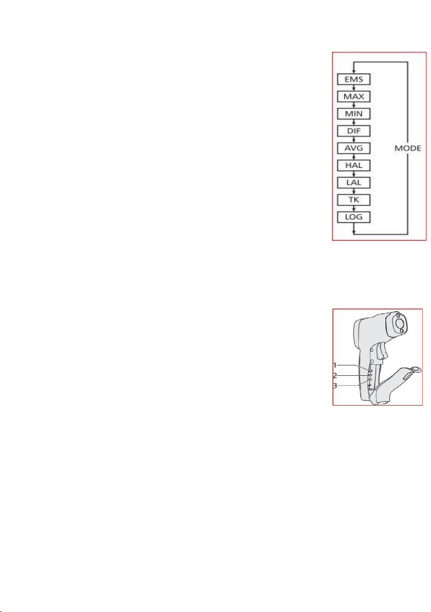
While in LOG mode, press the trigger and then press the “down” arrow
button until reach LOG “TrM”.
When LOG location “TrM” shows in the display, press “laser/backlight”
button. A tone will sound and the LOG location will automatically change
to “1”, all of the stored temperature transmit to pc.
11-6. Wireless Transmit Function
In the MAX, MIN, DIF, AVG mode, press the “USB” button to stir up
the Wireless Transmit function, “USB” will be displayed on the upper
right corner of the LCD.
Press the USB button again; this function will be turned off.
After the Wireless Transmit function is turned on, firstly connect the USB
interface (RF 433MHz) to the computer and wireless transmitter and open
the software on the computer, then the IR temperature readings on the
Thermometer will be transmitted to the computer.
Wireless Transmit is allowed to use within a 30m area.
Note: Data will only be transmitted under SCAN state.
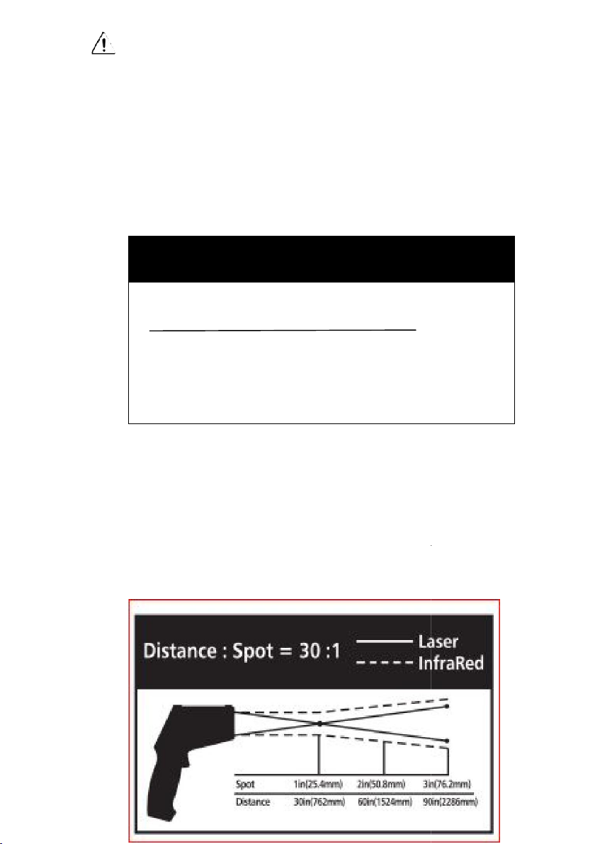
Note: Measurement considerations
Holding the meter by its handle, point the IR sensor toward the object
whose temperature is to be measured.
The meter automatically compensates for temperature deviations from
ambient temperature. Keep in mind that it will take up to 30 minutes to
adjust to wide ambient temperatures are to be measured followed by high
temperature measurements, some time (several minutes) is required after
the low (and before the high) temperature measurements are made.
This is a result of the cooling process, which must take place for the IR
sensor.

12. Battery Replacement
As battery power is not sufficient, LCD will display replacement
with one new 9V battery is required.
Open battery cover, then take out the battery from instrument and replace
with a new 9V battery and place the battery cover back.
13. Notes
How it Works
Infrared thermometer measures the surface temperature of an object. The
unit’s optics sense emitted, reflected, and transmitted energy, which is
collected and focused on to a detector. The unit’s electronics translate the
information into a temperature reading, which is display on the unit. In
units with a laser, the laser is used for aiming purposes only.
Field of View
Make sure that the target is larger than the unit’s spot size. The smaller the
target, the closer you should be to it. When accuracy is critical, make sure
the target is at least twice as large as the spot size.

14. Distance & Spot Size
As the distance (D) from the object increases, the spot size (S) of the area
measured by the unit becomes larger.
14-1. Locating a hot Spot
To find a hot spot aim the thermometer outside the area of interest,
then scan across with an up and down motion until you locate hot spot.
14-2. Reminders
Not recommended for use in measuring shiny or polished metal surfaces
(stainless steel, aluminum, etc.). See Emissivity
The unit cannot measure through transparent surfaces such as glass. It
will measure the surface temperature of the glass instead.
Steam, dust, smoke, etc., can prevent accurate measurement by
obstructing the unit’s optics.
14-3. Emissivity
Emissivity is a team used to describe the energy-emitting characteristics
of materials. Most (90% of typical applications) organic materials and
painted or oxidized surfaces have an emissivity of 0.95 (pre-set in the
unit). Inaccurate readings will result from measuring shiny or polished
metal surfaces. To compensate, cover the surface to be measured with
masking tape or flat black paint. Allow time for the tape to reach the
same temperatures as the material underneath it. Measure the
temperature of the tape or painted surface.

14-4. Emissivity Values
Substance Thermal Emissivity Substance
Thermal
Emissivity
Asphalt 0.90 to 0.98 Cloth(black) 0.98
Concrete 0.94 Human skin 0.98
Cement 0.96 Lather 0.75 to 0.80
Sand 0.90 Charcoal(powder) 0.96
Earth 0.92 to 0.96 Lacquer 0.80 to 0.95
Water 0.92 to 0.96 Lacquer(matt) 0.97
Ice 0.96 to 0.98 Rubber(black) 0.94
Snow 0.83 Plastic 0.85 to 0.95
Glass 0.90 to 0.95 Timber 0.90
Ceramic
0.90 to 0.94
Paper
0.70 to 0.94
Marble 0.94 Chromium oxides 0.81
Plaster 0.80 to 0.90 Copper oxides 0.78
Mortar 0.89 to 0.91 Iron oxides 0.78 to 0.82
brick 0.93 to 0.96 Textiles 0.90
15. Maintenance & Clearing
Repairs or serving aren’t covered in this manual should only be
performed by qualified personnel.
Periodically wipe the case with a dry cloth. Don’t use abrasive or solvents
on this instrument.
When serving, use only specified replacement parts.
Table of contents
Other MarMonix Thermometer manuals
Popular Thermometer manuals by other brands

ThermoWorks
ThermoWorks I.R.F.S. operating manual

Velleman
Velleman DVM105 user manual

Test Equipment Depot
Test Equipment Depot TRACEABLE FULL-SCALE PLUS THERMOMETER instructions

Fluke
Fluke 65 Gebrauchsanweisung

Exergen
Exergen TemporalScanner TAT-2000-EC quick start

ellemka
ellemka Jumper JPD-FR100 instruction manual