Marquee HAVANA User manual

HAVANA GAZEBO
Assembly Instructions
4 x 3 M
Item number: 0182364
WITH POLYCARBONATE ROOF

01 / 18
No. Parts Qty Step
4
1
4
5
8
2
2
2
2
3
4
6
2
4
8
4
9
12
13
23
14
2
4 11
4 11 1 10
1
4 1
4 6
4 6
47
8
8
84
5
4 13
4 13
4 13
4 11A
B
C
C
D
E
F
F
F
G
G
H
I
J
K
L
M
N
O
P
1
B2
1
2
1
2
1
G2
H1
2
H
No. Parts Qty Step
List of Parts
LEG POST
BEAM
BEAM
BEAM
BEAM
CORNER RIB
MID RIB
CURTAIN RAIL
CURTAIN RAIL
CURTAIN RAIL
ROOF JOINT
ROOF JOINT
ROOF JOINT
EDGE PROTECTOR
EDGE PROTECTOR
EDGE PROTECTOR
STRENGTHEN BAR
MID RIB CONNECTOR
CORNER RIB CONNECTOR
CORNER BEAM COVER
MID BEAM COVER
FOOT PLATE
LOWER TOP PLATE
UPPER TOP PLATE
long, right
long, left
short, right
short, left
long, right
long, left
short
middle
left
middle
left
right
right
...
...
.
.
.
..
.
.
...
2
3
5
6
2
3
4
6
2
3
5
6
7
8
12
13
3
14
3
14
2
3
9
8
9
10

No. Parts Qty
Step
4 2
4 13
8 13
1~5
8 14
6
104 14
4 14
4 14
16 15
4
11
12
13
411
12
4
4
4
4Q
R
S
T
U
V
W
X
Y
Z
1
2
3
4
5
6
7
No. Parts Qty
Step
24
32
139
02 / 18
BEAM CONNECTOR
CORNER RIB CAP
MID RIB CAP
M6 x 16
M6 x 16
ST4 x 25
ST4 x 12
HOOK
MOSQUITO NETS
FABRIC SIDE PANELS
ROOF PANEL
ROOF PANEL
ROOF PANEL
ROOF PANEL
STAKE
ALLEN WRENCH
left, upper
left, lower
ROOF PANEL
ROOF PANEL
right, upper
right, lower
middle, upper
middle, lower
14
5
8
11
12
13
11
12
11
12
13
11
12
4
5
7~9
10
13
List of Parts
NOTE:
1. The gazebo is shipped in two cartons. These cartons are very heavy and require a mechanical
aid to lift. Be careful when lifting by two persons.
2. Carefully take all the parts out from the carton. The parts are identified by removable stickers.
Please place the parts for each step on a flat protected nonabrasive staging area.
Identify them with the list of parts to make sure that you have all parts before assembly.
3. Please keep or record the parts list, it could be useful to reorder some parts for service if necessary.
..
..
.
.
. .
.
..
.

Please read these instructions completely before starting assembly
Safety Advice
The gazebo must be positioned and fixed ona flat level surface.
Dispose of all plastic bags safely. Keep them out of thereach of children.
Keep children and pets away from the assembly area until the work is completed.
Always wear proper safety gear including work shoes, gloves.
Do not attempt to assemble the gazebo in medium windy or wet condition.
Do not placeyour gazebo in an area exposed to excessivewind.
If using power tools or a ladder, always followthe manufacturer safety instructions.
Hot items such as grills, blowtorches, heaters etc. must not be storedin thegazebo.
Do not cook or lit fireworks near the gazebo.
Avoid vandalism, abuse, fallingor thrown objects, or accumulation of snow.
Tips: Please don't destroy boxes until completely assembled.
Do not tighten bolts immediately. You can install loose by cordless drill with Philips head. Adjust to make all
components in place before you tighten all screws by Philips Screwdriver. Power tools may over tighten fittings.
Cool temperature condition is recommended for easy assembly.
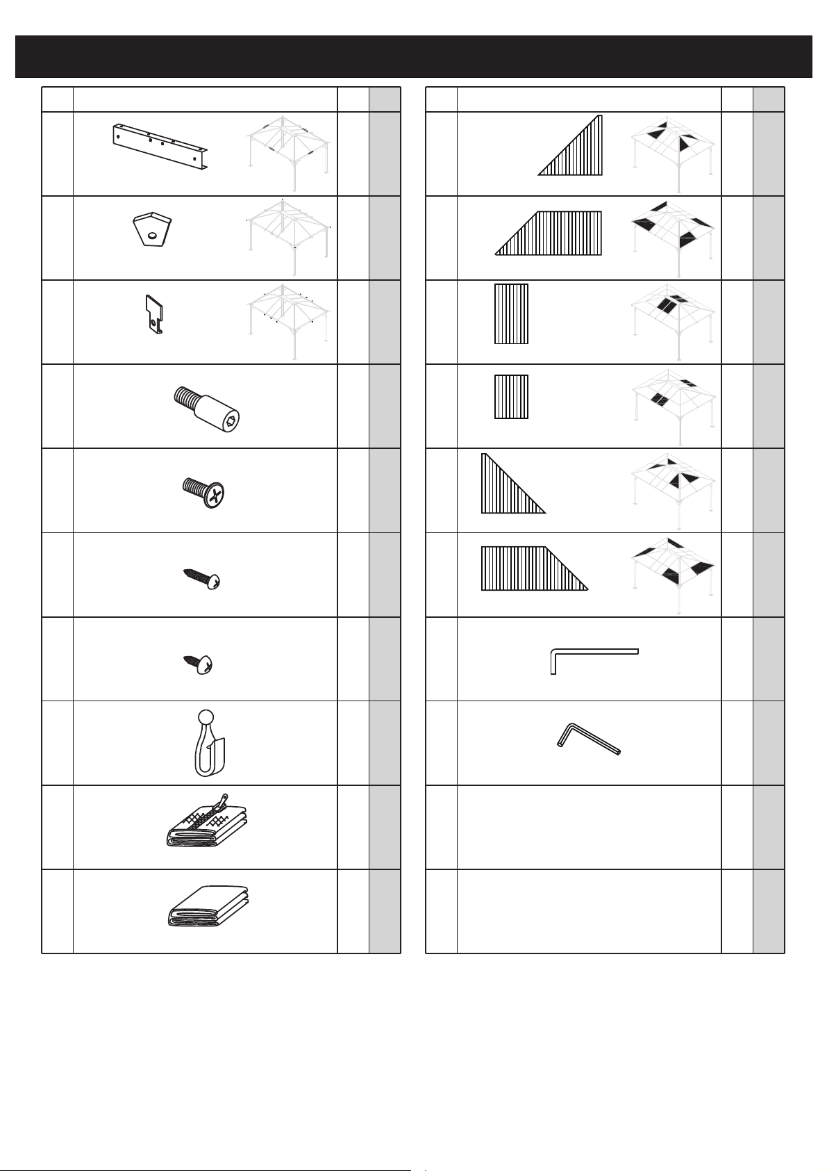
Make sure you have all the necessary parts. The List of Parts has the corresponding step number referenced
to each part. We recommend that while you go through the list, make staging areas for each step and place the
parts necessary for each step in these areas. This will save you time and effort during assembly.
03 / 18
List of Parts.................................................................................................. 1-2
Table of Contents......................................................................................... 3
STEP 1 Assemble the Leg posts.....................................(ca. 5min)........... 4
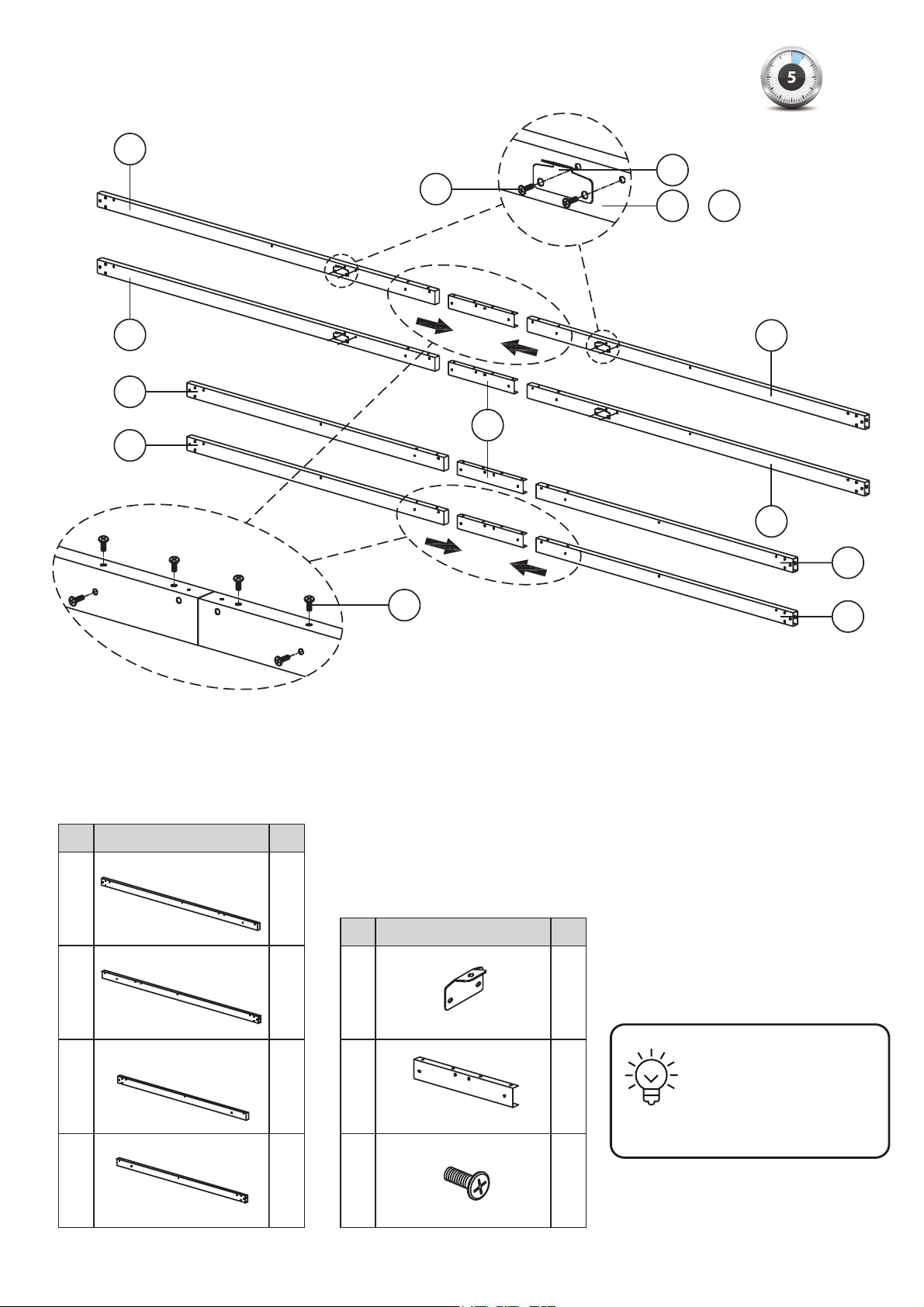
STEP 2 Assemble the Beams..........................................(ca. 5min).......... 5
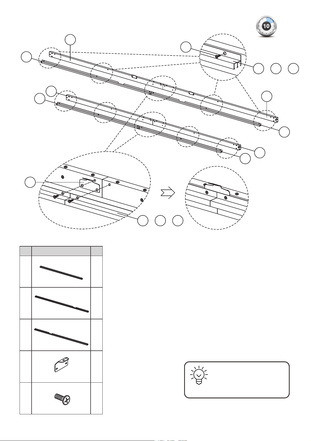
STEP 3 Attach the Rails to the Beams............................(ca. 10min)......... 6
STEP 4 Attach short Beams to the Leg posts.................(ca. 10min)......... 7
STEP 5 Attach long Beams to the Leg posts..................(ca. 15min)......... 8
STEP 6 Install the Beam covers......................................(ca. 10min)......... 9
STEP 7 Assemble four Corner ribs.................................(ca. 5min)........... 10
STEP 8 Put up Lower top plate and Corner ribs.............(ca. 15min)......... 11
STEP 9 Install the Mid ribs..............................................(ca. 5min)........... 12
STEP 10 Install the Upper top plate.................................(ca. 5min)........... 13
STEP 11 Assemble the large Roof panels........................(ca. 20min)......... 14
STEP 12 Put up the Roof panels.......................................(ca. 15min)......... 15
STEP 13 Install Edge protectors and Rib caps.................(ca. 15min)......... 16
STEP 14 Put up Fabric side panels and Mosquito nets....(ca. 10min)......... 17
STEP 15 Secure the Gazebo to the ground.......................(ca. 5min)........... 18
Thank you for choosing the Havana Gazebo!
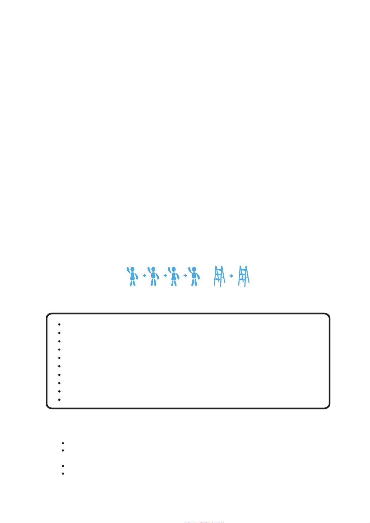
All steps can be completed by 4 people. The assembly take about two and a half hours.
Proper tools: Two ladders, Philips screwdrivers, Gloves, Spirit Level.
Note: Your gazebo is a non-permanent structure. It is designed for leisure use
and is not a shelter against adverse weather conditions.
Table of Contents

A 4
N 4
A
N
U 16
U
A A A A
N N N N
04 / 18
STEP 1
No. Components in this step Qty
LEG POST
FOOT PLATE
M6 x 16
Assemble the Leg posts
TIPS
Do not tighten bolts immediately, install loose.
Adjust foot plate to make all screws are in place
before you tighten all screws by hand.
Place the posts parallel to each other on level ground.
Slide FOOT PLATE (N) into LEG POST (A) from the end.
Fasten each plate to the leg post using 4 bolts (U).

B1
B2
C1
C22
2
2
2
U
J
U
B1
B1
C1
C1
C2
C2
Q
B2B1/
05 / 18
STEP 2
No. Components in this step Qty
J
Q
U 32
4
4
No. Components in this step Qty
BEAM
BEAM
BEAM
BEAM
long, right
long, left
short, right
short, left
MID RIB CONNECTOR
BEAM CONNECTOR
M6 x 16
B2
B2
Assemble the Beams
TIPS
Left the 2 middle
holes of each beam
connector not
screwed for STEP 3.
2-A Screw two bolts (J) to assemble the MID RIB CONNECTOR (J)
onto the long BEAM (B1) and (B2).
2-B Use BEAM CONNECTOR (Q) to combine the long BEAM (B1)
and (B2), then secure tightly with 6 bolts (U) only.
2-C Use BEAM CONNECTOR (Q) to combine the short BEAM (C1)
and (C2), then secure tightly with 6 bolts (U) only.
Find all components in this step and place them on a level ground.
Repeat this step until all beams are assembled.

F1
F2
J
4
2
2
4
F
F2
F1
F
B1
B2
FC1
C2
FF2
F1//
U
U 24
FF
F1//
J
06 / 18
STEP 3
No. Components in this step Qty
CURTAIN RAIL
CURTAIN RAIL
CURTAIN RAIL
long, right
long, left
short
MID RIB CONNECTOR
M6 x 16
2
Attach the Rails to the Beams
TIPS
Make sure the MID RIB
CONNECTOR (J) is
between beams and rails.
Find all components in this step and place them on a level
ground as shown.
3-A Secure the short CURTAIN RAIL (F) and the MID RIB
CONNECTOR (J) to the short BEAM (C1 & C2) with
6 bolts (U).
3-B Secure the long right CURTAIN RAIL (F1), the long left
CURTAIN RAIL (F2) and MID RIB CONNECTOR (J) to
the long BEAM (B1 & B2) with 6 bolts (U).
Repeat this step until all rails are assembled.

T
I
U
07 / 18
STEP 4
I 4
T 12
U
No. Components in this step Qty
8
8 1
M6 x 16
M6 x 16
ALLEN WRENCH
STRENGTHEN BAR
Attach short Beams to the Leg posts
TIPS
Place two sets of leg posts
in opposite direction to raise
the door frame easier.
Find all parts in this figure and place them on a level ground.
4-A Combine the short BEAM (C1 & C2) and LEG POST (A)
with 3 bolt (T). Use Allen wrench (8) to tighten the bolts.
4-B Install the STRENGTHEN BAR (I) to the BEAM (C1 & C2)
and LEG POST (A) with 2 bolt (U).
Repeat this step until 4 posts are assembled.

T
I
U
I 4
T 12
U
No. Components in this step Qty
8
08 / 18
8 1
ALLEN WRENCH
M6 x 16
M6 x 16
STRENGTHEN BAR
Attach long Beams to the Leg postsSTEP 5
At least four
persons are
needed for
this step.
ATTENTION
Find all components and long BEAM (B1 & B2) in this step.
5-A Raise up two door frames of STEP 4 oppositely with rails inside.
5-B Combine the long BEAM (B1 & B2) and LEG POST (A) with 3 bolt (T). Use ALLEN
WRENCH (8) to tight the bolts.
5-C Install the STRENGTHEN BAR (I) to the BEAM (B1 & B2) and LEG POST (A) with 2 bolt (U).
Repeat this step until all lower frames are assembled.

L
M
U 32
4
4
L
L
M
W
W
09 / 18
STEP 6
No. Components in this step Qty
CORNER BEAM COVER
MID BEAM COVER
ST4 x 12
Install the Beam covers
Find all components in this step.
6-A Assemble the CONNER BEAM COVER (L) onto the corner of beams with 4 tapping screws (W).
6-B Assemble the MID BEAM COVER (M) onto the middle of beams with 4 tapping screws (W).
Repeat the step until 8 beam covers are assembled.
To make your gazebo look better, avoid leaving gaps between beam covers and beams.
TIPS
After this step you should place the gazebo frame
in its desired location.
Make sure all corners are squared at 90 degrees.
Then you can tighten all bolts by hand tool except
those on the mid rib connectors.

U
K4
4
4
D
U
K
D
K
D
10 / 18
STEP 7
No. Components in this step Qty
CORNER RIB
CORNER RIB CONNECTOR
M6 x 16
Assemble four Corner ribs
TIPS
Make sure the corner rib connectors
in the correct position and direction
as shown before tightening the bolts.
Find the longest CORNER RIB (D) and CORNER RIB CONNECTOR (K), place them
parallel to each other on a level ground.
Assemble CORNER RIB CONNECTOR (K) on the CORNER RIB (D) with a bolt (U).
Repeat the step until 4 corner rib connectors are assembled.

U
U
O
K
A
O 1
U 16
No. Components in this step Qty
STEP 8
11 / 18
LOWER TOP PLATE
M6 x 16
Put up Lower top plate and Corner ribs
8-A Assemble four CORNER RIB (D) onto the LOWER TOP PLATE (O) with 8 bolt(U).
Now the upper structure looks like ">-<" from top view.
8-B Move this upper structure up to the lower frame.
8-C Secure each CORNER RIB CONNECTOR (K) onto the LEG POST (A) with 2 bolts (U).
Repeat on all corners.
The upper structure is heavy, use support as needed.
Carefully move it by at least four persons.
The junction may twist through negligence.
At least two ladders are needed in this step.
ATTENTION
D
D
D

U 16
E8
No. Components in this step Qty
STEP 9
U
J
E
U
EO
12 / 18
MID RIB
M6 x 16
Install the Mid ribs
9-A Install one end of MID RIB (E) onto the LOWER TOP PLATE (O) with a bolt (U).
Use the hole of MID RIB (E) closest to the outside.
9-B Attach the other end of MID RIB (E) to the MID RIB CONNECTOR (J) on the beams,
by screwing a bolt (U).
Repeat this step until 8 mid ribs are assembled.
TIPS
Make sure the mid ribs
are installed in correct
direction as shown.

13 / 18
STEP 10
U
P
U
1P
3
No. Components in this step Qty
UPPER TOP PLATE
M6 x 16
Install the Upper top plate
Lift up the UPPER TOP PLATE (P) onto
the LOWER TOP PLATE (O).
Secure it with 3 bolts (U) bottom up through
the lower plate.
ATTENTION
The upper top plate is heavy, use support as needed.
At least two ladders are needed in this step.

14 / 18
STEP 11
4
4
1
4
2 4
3 4
5 4
6 4
4
G
4
4G2
G1
Expose this side to sunlight
Exposez ce côté au soleil
Keep these words side facing up
No. Components in this step Qty
1
2
X 4
G1
5
6
G2
X 4
3
4
G
X 4
ROOF PANEL
ROOF PANEL
ROOF PANEL
ROOF PANEL
left, upper
left, lower
right, upper
right, lower
ROOF PANEL
ROOF PANEL
middle, upper
middle, lower
ROOF JOINT
ROOF JOINT
middle
left
ROOF JOINT
right
Assemble the large Roof panels
Find all components in this step and place them on a
non-abrasive level ground. Keep the words side facing up
before assembling the large roof panels.
11-A Connect left upper PANEL (1) and lower PANEL (2)
with left ROOF JOINT (G1).
11-B Connect right upper PANEL (5) and lower PANEL (6)
with right ROOF JOINT (G2).
11-C Connect middle upper PANEL (3) and lower PANEL (4)
by middle ROOF JOINT (G).(Longer panel 3 is higher)
Repeat until 8 right triangle and 4 rectangular roof panels
are assembled.
ATTENTION
Work glove is essential in this step. Carefully follow
the assembly figure to ensure an easy installation.
Do not rip the films off the panel in this step.

15 / 18
STEP 12
1
1
1
1
2
2
2
2
33
33
44
44
5
5
5
5
6
6
6
6
1 3 3 5
2 4 4 6
5 3 3 1
6 4 4 2
5
1
6
2
2
6
1
5
Top view
Put up the Roof panels
Slide the large Roof panels into the groove of MID RIB (E) and CORNER RIB (D) as shown
successively. Use a rubber hammer to carefully tap each panel into the grooves.
ATTENTION
Place the words side of the
polycarbonate roof panels
toward the sun facing out.
Hold the roof panels until it is tight in
the rib grooves. It becomes dangerous
if you leave the gazebo alone before
you finish STEP 13.

16 / 18
STEP 13
4R
S 8
U
4
4
4
H1
H2
H
12
U
S
H
E
U
R
H
D
H1
2
No. Components in this step Qty No. Components in this step Qty
M6 x 16
EDGE PROTECTOR
EDGE PROTECTOR
EDGE PROTECTOR
middle
left
right
CORNER RIB CAP
MID RIB CAP
Install Edge protectors and Rib caps
H
H1H1H2
H2
13-A Insert the EDGE PROTECTOR (H1),(H),(H2) to ROOF PANEL (2),(4),(6) separately.
13-B Secure the CORNER RIB CAP (R) to CORNER RIB (D) with a bolt (U).
13-C Secure the MID RIB CAP (S) to CORNER RIB (E) with a bolt (U).
Repeat this step until all
edge protectors and rib
caps are assembled.
Roof panels and
ribs must be
aligned properly
during assembly
ATTENTION
to minimize any possibility
of leaking.

17 / 18
STEP 14
8 PCS
7 PCS
6 PCS5 PCS
V
4
Y
8
Z 4
X 104
ZYV
X
No. Components in this step Qty
HOOK
MOSQUITO NETS
FABRIC SIDE PANELS
ST4 x 25
Put up Fabric side panels and Mosquito nets
Mosquito nets
One piece mosquito net contains 14 hooks.
6 hooks on the short side, 8 hooks on the long side.
One piece side fabric side panel contains 12 hooks.
5 hooks on the short side, 7 hooks on the long side.
Fabric side panels
14-A Assemble the plastic HOOK (X) on FABRIC
SIDE PANELS (Z) and MOSQUITO NETS (Y).
14-B Put up the hooks into the curtain rails.
14-C Fix the tapping screw (V) onto curtain rails.

18 / 18
STEP 15
N
7
7 16
No. Components in this step Qty
STAKE
Secure the Gazebo to the ground
Fix the FOOT PLATE (N) into the ground by 16 STAKES (7).
Please ensure that you use anchors sufficient for your surface.
Good work! Your gazebo is ready for use!
TIPS
Although stakes are supplied to suit soft ground,
you can also secure the gazebo to a concrete floor
or a wood deck. You may need to purchase other
necessary fittings. If you anchor the gazebo on a
concrete floor, please use concrete screws, nuts
and washers. If you anchor it on a wood deck,
please use wood screws and washers.
This manual suits for next models
1
Table of contents
Other Marquee Outdoor Furnishing manuals
Popular Outdoor Furnishing manuals by other brands

Safavieh Outdoor
Safavieh Outdoor Nigel PAT5032 manual

Apex Garden
Apex Garden 22-YH-20S089HD Assembly instructions

Sunjoy
Sunjoy Heirloom Tete-a-Tete Assembly instructions

VISSCHER
VISSCHER MILANO instructions

Kozyard
Kozyard KZAHG1012GRA Assembly manual

Safavieh Outdoor
Safavieh Outdoor Montford CPT1002A Assembly

Replas
Replas PREMIER SETTING 1.8m In Ground Assembly instructions

Naterial
Naterial ZEFIR 3276007182972 Assembly, Use, Maintenance Manual

Lifetime
Lifetime 60205 Assembly instructions

GLITZHOME
GLITZHOME Patio Gray Aluminum Sectional Assembly instruction

sweeek.
sweeek. OVIEDO ACRD120KD manual

Sunjoy
Sunjoy L-GZ702PST manual