manuals.online logo
Brands
  1. Home
  2. •
  3. Brands
  4. •
  5. marset
  6. •
  7. Outdoor Light
  8. •
  9. marset Ginger 60/298 User manual

marset Ginger 60/298 User manual

ADVERTENCIAS
1. Se recomienda que la instalación sea realizada por un profesional.
2. Desconectar la conexión a red antes de ser manipulada.
3. Si el cable exible o cordón de esta luminaria está dañado, deberá sustituirse exclusivamente por el
fabricante o su servicio técnico o una persona de cualicación equivalente con objeto de evitar cualquier
riesgo.
4. Utilizar un paño suave, humedecido con agua y detergente neutro si fuera necesario. No utilizar alcohol o
otros disolventes.
5. Ninguna parte del aparato debe estar en contacto directo con el terreno o con sustancias químicas
agresivas (fertilizantes, herbicidas,cal etc).
6. Utilizar un cable de alimentación adecuado para instalaciones de exterior (tipo HAR H05/07 RN-F). Los
cables rígidos pueden comprometer la estanqueidad del prensaestopas.
WARNING
1. It is recommended that a professional electrician be responsible for installing the light.
2. Disconnect power supply before installation.
3. If the wire or exible cord is damaged,it must only be changed by the manufacturer, their Service Dept. or
qualied personnel in order to avoid risk.
4. Use a soft damp cloth, with soap or neutral detergent. Do not use alcohol or other solvents.
5. Keep away from aggressive agents and chemical substances (e.g. fertilizer, weed-killer, lime).
6. Use HAR H 05/07 RN-F exible cables or dedicated cables for outdoor use only. Stiff cables do not assure
the effectiveness of the cable gland.
ATTENTION
1. Il est recommandé de faire exécuter l’installation par un professionnel.
2. Débranchez la connexion au réseau avant toute manipulation.
3. Si le câble exible ou l du luminaire est endommagé, il conviendra de faire appel au fabricant, à son service
technique ou encore à une personne qualiée pour le remplacer et éviter ainsi tout risque fâcheux.
4. Pour nettoyer le luminaire, nous vous recommandons d’utiliser un chiffon doux humidié d’eau et de
détergent neutre, le cas échéant. N’utilisez pas d’alcool ni d’autres types de dissolvants.
5. Gardez l’appareil à l’abri de toute substance chimique agressive (engrais, désherbant, chaux).
6. Utiliser seulement des câbles souples type <HAR> H05/07 RN-F ou spécialement conçus pour un usage
à l’extérieur. L’emploi de câbles rigides risque de compromettre l’étanchéité du presse-étoupe.
HINWEISE
1. Wir empfehlen, die Installation von einem Fachmann vornehmen zu lassen.
2. Unterbrechen Sie die Verbindung zum Netz vor Beginn der Arbeit.
3. Wird das Kabel der Leuchte beschädigt, darf dieses nur durch den Hersteller, dessen technischen Service,
oder eine entsprechend qualizierte Person ausgetauscht werden, um eventuelle Risiken zu vermeiden.
4. Zur Reinigung der Leuchte empehlt es sich, ein weiches Tuch zu verwenden und dieses, falls nötig, mit
Wasser und einem neutralen Reiniger zu befeuchten. Alkohol oder Lösungsmittel sind zur Reinigung nicht
geeignet.
5. Die Leuchte darf nicht mit chemischen oder aggressiven Substanzen (wie z.B. Düngemittel, Unkrautvertil-
gungsmittel, Kalk) in Kontakt kommen.
6. Für den Außenbereich dürfen nur exible Kabel vom Typ <HAR> H05/07 RN-F o der typengleiche Kabel
verwendet werden. Starre Kabel können den Halt des Kabels in der Kabeldurchführung nicht gewährleisten.
Ginger 60/298
Instrucciones de montaje
Assembly Instructions
Instructions de montage
Montageanleitung
Joan Gaspar
1.1. Asegurar el correcto nivel del terreno alrededor
de la salida de la toma de red.
1.2. Preparar 4 puntos de anclaje con las medidas
facilitadas. (Ø12,5mm agujeros jación).
1.3. Pasar el cableado por el interior de la base (A)
de jación. Asegurar el correcto nivel de la base.
Fijar el conjunto de la base (A) utilizando los 4
puntos de jación utilizando la jación adecuada
para la supercie.
1.1. Make sure the ground around the outlet of the
mains socket is level.
1.2. Prepare 4 anchor points using the
measurements provided. (Ø12.5mm xing holes).
1.3. Run the wiring through the inside of the xing
base (A). Make sure the base is level. Attach the
base assembly (A) at the 4 attachment points using
the appropriate method for the surface.
1.1. Veillez à ce que le sol qui se trouve autour de la
sortie du raccordement secteur soit parfaitement à
niveau.
1.2. Préparez 4 points de xation en respectant les
cotes fournies (orices de xation Ø 12,5 mm).
1.3. Faites passer le câblage à l’intérieur de la base
de xation (A). Assurez la bonne mise à niveau de la
base. Fixez l’ensemble de la base (A) à l’aide des 4
points de xation en utilisant la méthode de scellement
la mieux adaptée à la nature de la surface.
1.1. Achten Sie auf die korrekte Höhe des Bodens im
Ausgangsbereich der Netzsteckdose.
1.2. Bereiten Sie 4 Verankerungspunkte mit den
vorgesehenen Maßen vor. (Ø12,5 mm
Befestigungslöcher).
1.3. Führen Sie die Kabel durch das Innere des
Bodensockels (A). Achten Sie auf die richtige Höhe des
Sockels.Befestigen Sie die Sockelbaugruppe (A) an
den 4 Befestigungspunkten mit der für den Untergrund
geeigneten Methode.
1
40cm max./ 35cm min.
30mm
8mm
120mm
120mm
Ø12mm max (x4)
Ø12mm max (x4)
· Disponible como accesorio.
· Available as an accessory.
· Disponible comme accessoire.
· Als Zubehör erhältlich.
1.2
1.1 1.3
A
0º
2
2.1. Aojar ambos pasadores roscados de la parte
superior del cuerpo central rectangular y extraer
cuidadosamente la tapa con el conjunto eléctrico (B).
2.2. Pasar el cable como muestra la Fig 2.2. Posicionar
y anclar el tubo principal al cuerpo central rectangular
con los dos tornillos.
2.1. Loosen both threaded pins from the top of the
rectangular central body and carefully remove the cover
with the electrical assembly (B).
2.2. Run the cable as shown in g 2.2. Position and
anchor the main tube to the rectangular central body
using the two screws supplied.
2.1. Desserrez les deux goujons letés de la partie
supérieure du corps central rectangulaire et retirez
précautionneusement le couvercle ainsi que l’ensemble
électrique (B).
2.2. Faites passer le câble comme indiqué sur la gure.
Positionnez et xez le tube principal au corps central
rectangulaire à l’aide des deux vis fournies.
2.1. Lösen Sie die beiden Gewindestifte im oberen Teil
des rechteckigen Mittelkörpers und entfernen Sie
vorsichtig die Abdeckung mit der elektrischen
Baugruppe (B).
2.2. Führen Sie das Kabel wie in Abb. 2.2 gezeigt.
Positionieren und verankern Sie das Hauptrohr am
rechteckigen Zentralkörper mit den beiden mitgelieferten
Schrauben.
DIN 912 M6x25
2.1
2.2
B
3
3.1. Posicionar ambos cables en un lateral del conector,
presionando hasta el fondo del mismo.
3.2. Aplicar presión en el pulsador superior del lateral
donde se han introducido los cables.
3.3. Repetir paso 3.1 & 3.2 en el otro extremo del
conector con el otro cable.
3.1. Position both cables on one side of the connector
and press all the way in.
3.2. Apply pressure to the top push-button on the side
where the cables were inserted.
3.3. Repeat steps 3.1 & 3.2 on the other side of the
connector with the other cable.
3.1. Placez les deux câbles d’un côté du connecteur et
poussez jusqu’au fond.
3.2. Exercez une pression sur le bouton supérieur du côté
où les câbles ont été insérés.
3.3. Répétez les étapes 3.1 et 3.2 de l’autre côté du
connecteur avec l’autre câble.
3.1. Positionieren Sie beide Kabel auf einer Seite des
Steckers und drücken Sie sie vollständig in den Stecker.
3.2. Üben Sie Druck auf den oberen Schalter auf der Seite
aus, an der die Kabel eingeführt wurden.
3.3. Wiederholen Sie Schritt 3.1 & 3.2 am anderen Ende
des Steckers mit dem anderen Kabel.
Rojo (+), Red (+)
Negro (-), Black (-)
3.1
20 mm
3.2
red black red black
20 mm
CONNEXION 1-10V (OPTIONNEL)
4.1. Placez les deux câbles d’un côté du connecteur et
poussez jusqu’au fond.
4.2. Exercez une pression sur le bouton supérieur du côté
où les câbles ont été insérés.
4.3. Répétez les étapes 4.1 et 4.2 de l’autre côté du
connecteur avec l’autre câble.
ANSCHLUSS 1-10V (OPTIONAL)
4.1. Positionieren Sie beide Kabel auf einer Seite des
Steckers und drücken Sie sie vollständig in den Stecker.
4.2. Üben Sie Druck auf den oberen Schalter auf der Seite
aus, an der die Kabel eingeführt wurden.
4.3. Wiederholen Sie Schritt 4.1 & 4.2 am anderen Ende
des Steckers mit dem anderen Kabel.
4
CONEXIÓN 1-10V (OPCIONAL)
4.1. Posicionar ambos cables en un lateral del conector,
presionando hasta el fondo del mismo.
4.2. Aplicar presión en el pulsador superior del lateral
donde se han introducido los cables.
4.3. Repetir paso 4.1 & 4.2 en el otro extremo del
conector con el otro cable.
CONNECTION 1-10V (OPTIONAL)
4.1. Position both cables on one side of the connector
and press all the way in.
4.2. Apply pressure to the top push-button on the side
where the cables were inserted.
4.3. Repeat steps 4.1 & 4.2 on the other side of the
connector with the other cable.
1-10V: Azul(+), Blue (+)
1-10V: Blanco (-), White (-)
4.1
20 mm
4.2
blue white blue white
20 mm
5
5.1. Colocar el cableado (D) en el interior del tubo
rectangular (F), posteriormente apretar ambos
pasadores roscados.
5.1. Place the wiring (D) inside the rectangular tube
(F), then tighten both threaded pins.
5.1. Placez le câblage (D) à l’intérieur du tube
rectangulaire (F), remettre le couvercle en place et serrer
les deux goujons letés.
5.1. Platzieren Sie die Kabel (D) in das Innere des
Rechteckrohrs (F), dann die Abdeckung und ziehen Sie
sie fest.
D
F
6
6.1. Colocar el embellecedor (C) de base en el tubo
central.
6.1. Slip the base trim (C) over the central tube.
6.1. Placez l’élément décoratif (C) de la base sur le tube
central.
6.1. Setzen Sie die Zierkappe (C) des Sockels auf das
Mittelrohr.
A
8
8.1. Conectar los conectores (G).
8.2. Introducir el cableado en el interior del tubo redondo
8.1. Connect the connectors (G).
8.2. Place the wiring inside the tube.
8.1. Branchez les connecteurs (G).
8.2. Placez le câblage à l’intérieur du tube.
8.1. Verbinden Sie die Stecker (G)
8.2. Führen Sie das Kabel in das Rundrohr ein.
8.2
8.1
click
G
7
7.1. Preparar el conjunto central para poder realizar
las conexiones.
7.2. Colocar la funda termoretráctil general en una
de las mangueras. Realizar las conexiones como
muestra la Fig 7.2. Centrar la funda termoretráctil
exterior y aplicar calor con una pistola de aire
caliente.
7.3. Posicionar y anclar con los 3 tornillos laterales
de la jación.
7.1. Set up the central assembly in preparation to
make the connections.
7.2. Place the heat shrink sleeve around one of the
sheaths. Connect as shown in Fig. 7.2. Center the
outer heat shrink sleeve and apply heat with a hot
air gun.
7.3. Position and secure using the 3 screws
supplied.
7.1. Préparez l’ensemble central pour pouvoir
procéder aux raccordements.
7.2. Placez la gaine thermorétractable générale sur
l’un des câbles. Procédez aux raccordements
comme indiqué sur la gure 7.2. Centrez la gaine
thermorétractable extérieure et appliquez de la
chaleur à l’aide d’un pistolet thermique.
7.3. Positionnez et xez le corps à l’aide des 3 vis
latérales fournies.
7.1. Bereiten Sie die Zentralbaugruppe so vor, dass
die Anschlüsse vorgenommen werden können.
7.2. Stecken Sie den Gesamt-Schrumpfschlauch
auf eine der Leitungen. Stellen Sie die Anschlüsse
wie in Abb. 7.2 gezeigt her. Zentrieren Sie den
äußeren Schrumpfschlauch und erhitzen Sie ihn mit
einer Heißluftpistole.
7.3. Positionieren und verankern Sie mit den 3
seitlichen Schrauben der mitgelieferten Fixierung.
7.1 7.2
7.3
NN
L
L
· Este símbolo en su equipo o embalaje indica que el presente producto no puede ser tratado como
residuo doméstico normal, sino que debe entregarse en el correspondiente punto de recogida de equipos
eléctricos y electrónicos. Para recibir información detallada sobre el reciclaje de este producto, por favor,
contacte con su ayuntamiento, su punto de recogida más cercano o el distribuidor donde adquirió el
producto.
· This symbol on the product or its packaging indicates that it must not be treated as household waste.
It should, in fact, be handed in at a recognised collection point for recycling electrical and electronic
equipment. For more detailed information about the recycling of this product, please contact your local
city ofce, your household waste disposal service or the shop where you purchased the product.
· Le symbole représenté sur l’appareil ou l’emballage signie que le produit ne peut être traité comme
un déchet domestique normal, et doit par conséquent être déposé dans un point de collecte réservé
aux appareils électriques et électroniques. Pour en savoir plus sur le recyclage de ce produit, veuillez
vous adresser auprès de votre mairie, an de connaître le point de collecte le plus proche, ou contacter
le distributeur qui vous a vendu le produit.
· Dieses Symbol auf dem Produkt oder der Verpackung zeigt an, dass diese nicht als normaler Hausmüll
behandelt werden dürfen, sondern den entsprechenden Stellen für Sondermüll zugeführt werden
müssen. Für weitere Informationen zum Thema Sondermüll wenden Sie sich bitte an Ihre Stadtverwaltung,
die nächste Annahmestelle oder den Händler, bei dem Sie das Produkt erworben haben.
Datos Técnicos
Luminaria para uso exterior
Factor de Potencia: 1
Lámpara a utilizar:
Ginger 60/298
LED SMD 35,5W 2700K 1,05A (incluido)
Technical Data
Light tting for outdoor use
Power Factor: 1
Bulb to be used:
Ginger 60/298
LED SMD 35,5W 2700K 1,05A (included)
Données techniques
Luminaire pour usage extérieur.
Facteur de puissance : 1
Ampoule :
Ginger 60/298
LED SMD 35,5W 2700K 1,05A (inclus)
Technische Daten
Leuchte für den Außenbereich.
Leistungsfaktor: 1
Empfohlenes Leuchtmittel:
Ginger 60/298
LED SMD 35,5W 2700K 1,05A (inbegriffen)
MARSET ILUMINACIÓN SA · CTRA. DE RUBÍ 284 · 08228 TERRASSA (BARCELONA) · SPAIN · WWW.MARSET.COM REV. 01
IP65
Dimmable
· Aislamiento básico más aislamiento reforzado. Toma de tierra: excluida.
· Basic insulation plus second insulation or both replaced by reinforced insulation. Earthing: excluded.
· Isolation de base + isolation renforcée. Prise de terre: exclue.
· Grundisolierung plus verstärkte Isolierung. Erdung: Exklusive.
100-230 VAC - 50/60 Hz
1-10V
9
9. Encajar el conjunto de la pantalla (G) dentro del tubo
(H), centrar los dos agujeros (I) y jar la pantalla con los
tornillos (J).
9. Insert the shade assembly (G) into the tube (H), align
the two holes (I) and fasten the shade with the screws
(J).
9. Emboîtez l’ensemble de l’abat-jour (G) à l’intérieur
du tube (H), centrez les deux orices (I) et xez le tout
à l’aide des vis (J).
9. Montieren Sie die gesamte
Lampenschirm-Baugruppe (G) an das Rohr (H),
zentrieren Sie die zwei Löcher (I) und xieren Sie den
Lampenschirm mit den Schrauben (J).
9.1 H
G
J
I

Other marset Outdoor Light manuals

marset Lab 35/60 B User manual

marset

marset Lab 35/60 B User manual

marset SCANTLING P73 & S User manual

marset

marset SCANTLING P73 & S User manual

marset POLO User manual

marset

marset POLO User manual

marset MERCER User manual

marset

marset MERCER User manual

marset LaFlaca User manual

marset

marset LaFlaca User manual

marset Joan Gaspar TXL 2019 User manual

marset

marset Joan Gaspar TXL 2019 User manual

marset FUNICULI User manual

marset

marset FUNICULI User manual

marset Lluis Porqueras Funiculi A Fabric User manual

marset

marset Lluis Porqueras Funiculi A Fabric User manual

marset Ginger 15C User manual

marset

marset Ginger 15C User manual

marset Jaima P307.54 User manual

marset

marset Jaima P307.54 User manual

marset FUNICULI A User manual

marset

marset FUNICULI A User manual

marset Santorini A Fixed Stem User manual

marset

marset Santorini A Fixed Stem User manual

marset POLO User manual

marset

marset POLO User manual

marset Plaff-on! 16 IP65 User manual

marset

marset Plaff-on! 16 IP65 User manual

marset Lab B35 User manual

marset

marset Lab B35 User manual

marset Lluis Porqueras Funiculi fabric A User manual

marset

marset Lluis Porqueras Funiculi fabric A User manual

marset Copernica P190 User manual

marset

marset Copernica P190 User manual

marset kaschkasch Bolita User manual

marset

marset kaschkasch Bolita User manual
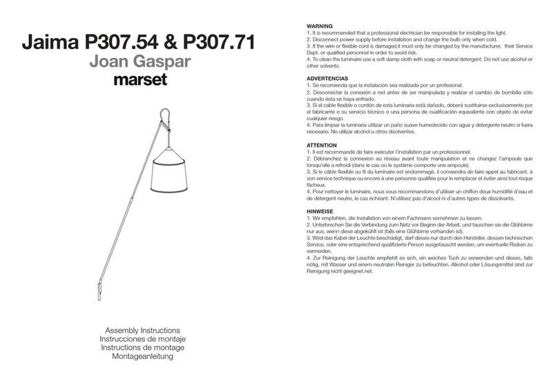
marset Ginger 20 M User manual

marset

marset Ginger 20 M User manual

marset Francesc Rife Lab 35 A User manual

marset

marset Francesc Rife Lab 35 A User manual

marset AMANITA User manual

marset

marset AMANITA User manual

marset Jaima P207 User manual

marset

marset Jaima P207 User manual

marset FUNICULI A User manual

marset

marset FUNICULI A User manual

marset ZOC IP65 User manual

marset

marset ZOC IP65 User manual
Popular Outdoor Light manuals by other brands

Sunbeam 30310684 instruction manual

Sunbeam

Sunbeam 30310684 instruction manual

NOMA NOBELA 052-4497-0 instruction manual

NOMA

NOMA NOBELA 052-4497-0 instruction manual

LIGMAN RA-10772 installation manual

LIGMAN

LIGMAN RA-10772 installation manual

Overland Vehicle Systems UFO Solar Camp Light & Speaker instruction manual

Overland Vehicle Systems

Overland Vehicle Systems UFO Solar Camp Light & Speaker instruction manual

Trilux 8841 LED Mounting instructions

Trilux

Trilux 8841 LED Mounting instructions

IKEA HOSTFEST manual

IKEA

IKEA HOSTFEST manual

Sunnydaze Decor INA-900 manual

Sunnydaze Decor

Sunnydaze Decor INA-900 manual

LIGMAN ALD-30071 instruction manual

LIGMAN

LIGMAN ALD-30071 instruction manual

SLV Elektronik ROX ACRYL POLE Series operating manual

SLV Elektronik

SLV Elektronik ROX ACRYL POLE Series operating manual

Urban Electric MARKHAM Assembly and mounting instructions

Urban Electric

Urban Electric MARKHAM Assembly and mounting instructions

JONATHAN Y JYL6602 quick start guide

JONATHAN Y

JONATHAN Y JYL6602 quick start guide

Beachside Lighting MB-SERIES quick start guide

Beachside Lighting

Beachside Lighting MB-SERIES quick start guide

BEMKO JASPER JAS1-030DG installation instructions

BEMKO

BEMKO JASPER JAS1-030DG installation instructions

Würth POWERQUAD M AC-R Translation of the original operating instructions

Würth

Würth POWERQUAD M AC-R Translation of the original operating instructions

Lights LampLust Elloway installation instructions

Lights

Lights LampLust Elloway installation instructions

Unilamp VAREE instruction manual

Unilamp

Unilamp VAREE instruction manual

HQ HQLSEASYWW230V user manual

HQ

HQ HQLSEASYWW230V user manual

Sygonix Catania operating instructions

Sygonix

Sygonix Catania operating instructions

manuals.online logo
manuals.online logoBrands
  • About & Mission
  • Contact us
  • Privacy Policy
  • Terms and Conditions

Copyright 2025 Manuals.Online. All Rights Reserved.