-4-
2. DESCRIPTION
The Digital RCD Tester is ideally suited for the testing of
Residual Current Protection Devices, in compliance with the 17th
Edition of the IEE Wiring Regulations.
The tester is designed to test the most common RCDs in use,with
a selector switch providing Fast, I and ½ Trip current settings.
The Fast setting provides 150mA trip current for RCDs not
exceeding 30mA. The I setting provides full rated trip current,
which should cause the RCD under test to trip.The ½ setting
provides half the rated trip current whereby the RCD should not
trip.
Other features include a polarity switch with 0° and 180°settings
which permits a test cycle to commence with a positive or
negative going wave form from the zero cross-over point. The
facility to establish whether the system under test is correctly
wired is provided by means of neon lamps and monitoring of the
voltage present on the earth terminal.
The instrument has thermal and fuse protection. The thermal
protection provides a time delay between tests, which will vary
with the range of model. When the time delay is in operation the
READY symbol is disabled. At the end of the time delay the
READY symbol is displayed and testing can continue.
-5-
3. OPERATING INSTRUCTIONS
Preparation
Note 1
Note that, when the RCD is tripped during the RCD testing procedure,
mains power will be removed from all electrical equipment connected
to the mains circuit that is protected by the RCD.
Similarly, all connected equipment will re-start when the RCD is
reset at certain stages in the testing procedure.
There are safety implications associated with both these
occurrences that should be taken into account.
For this reason it is recommended that all relevant equipment is
switched off and disconnected from the mains circuit before RCD
testing begins.
Note 2
In addition, some equipment may have a level of earth leakage that is
significant. For example, a leakage of 3mA can be typical of PCs.
Since a 30mA RCD MUST trip before 30mA leakage is detected,
and MAY trip at a level of earth leakage as low as 22mA, a mains
circuit with eight PCs connected may be operating with enough
earth leakage to cause an RCD to trip unexpectedly even before the
RCD testing procedure is begun. Under these conditions, the RCD
tripping characteristics cannot be measured accurately by the RCD
tester.
For the purpose of measuring accurately the sensitivity of the RCD
to earth leakage currents, it is recommended that all relevant
equipment is switched off and disconnected from the mains circuit
before RCD testing begins.
-6-
Note 3
Thirdly, certain types of equipment should be taken into account,
which contain capacitors or which contain motors. If these are
left connected and powered ON while the RCD testing procedure
is followed, the effect of stored capacitance or motor free-
wheeling can be to inject power into the disconnected mains
circuit after the RCD has tripped, causing a delay in the collapse
of the voltage in this circuit. As a result, the RCD tester may
record considerably longer RCD tripping times than may be truly
the case.
For the purpose of measuring accurately the response time of the
RCD, it is recommended that all relevant equipment is switched
off and disconnected from the mains circuit before RCD testing
begins.
To operate
For testing RCDs to BS EN 61557
To operate the RCD, the tester should be connected to a
convenient outlet socket on the electrical circuit supplied from
the RCD to be tested. The mains lead provided with the
instrument facilitates this connection as one end plugs into the
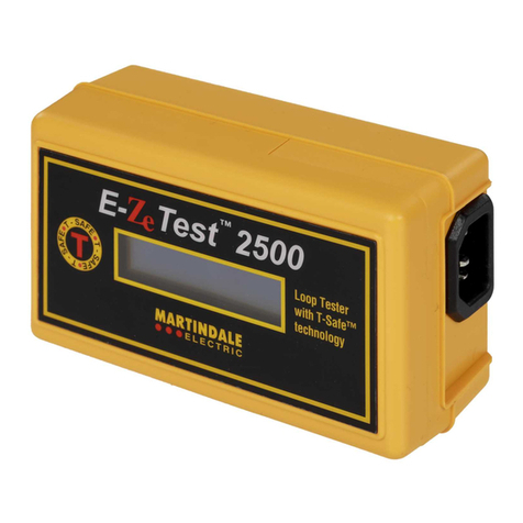
CEE 22 (IEC 320) socket at the top of the instrument while the
other end allows connection to the outlet socket with a suitable
mains plug.
-7-
(A) Connect the mains lead into the tester by means of the
IEC socket provided.
(B) Connect the mains lead to a socket outlet supplied from
the RCD to be tested.
(C) Set the trip current selector switch to the current rating of
the RCD to be tested. Set the range switch to I and the
polarity switch to 0°. It is recommended that the test is
repeated with the switch in the 180°position.
(D) Switch on the supply and check that both lamps on the
tester, marked P/N and P/E, have illuminated . If this is
the case then proceed with the test. If either or both of
the lamps are off, discontinue the test and correct the
wiring fault before proceeding. (An indication of
possible wiring faults can be found on page 9).
(E) To proceed with the test the READY symbol must be
displayed. Press and hold the test switch and the reading
displayed will be the time taken in mSec for the RCD to trip.
(F) Should the RCD under test fail to trip within 2000
milliseconds the OVER RANGE symbol on the tester
will indicate that the unit has failed. Where the RCD
under test trips within 500 or 2000 milliseconds, the trip
time will be displayed on the LCD. With a fault current
flowing equivalent to 100% of the rated tripping current of
the RCD, the device will open in less than 200ms.
(G) The RCD should also be tested to ensure that it can
withstand half the rated trip current without tripping. Set
the range switch to ½ then test as before. The RCD under
test should not trip and the OVERRANGE symbol will
indicate a successful test after 2000 milliseconds have
elapsed.

