-6- -7-
(A) Connect the mains lead into the tester by means of the
IEC socket provided.
(B) Connect the mains lead to a socket outlet supplied from
the RCD to be tested.
(C) Set the trip current selector switch to the current rating of
the RCD to be tested. Set the range switch to I and the
polarity switch to 0°. It is recommended that the test is
repeated with the switch in the 180°position.
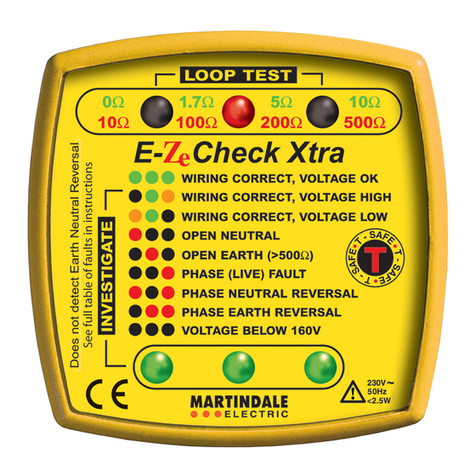
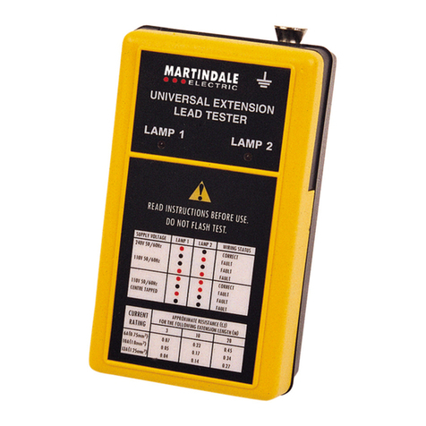
(D) Switch on the supply and check that both lamps on the
tester, marked P/N and P/E, have illuminated . If this is
the case then proceed with the test. If either or both of
the lamps are off, discontinue the test and correct the
wiring fault before proceeding. (An indication of
possible wiring faults can be found on page 9).
(E) To proceed with the test the READY symbol must be
displayed. Press and hold the test switch and the reading
displayed will be the time taken in mSec for the RCD to
trip.
(F) Should the RCD under test fail to trip within 2000
milliseconds the OVER RANGE symbol on the tester
will indicate that the unit has failed. Where the RCD
under test trips within 500 or 2000 milliseconds, the trip
time will be displayed on the LCD. With a fault current
flowing equivalent to 100% of the rated tripping current of
the RCD, the device will open in less than 200ms.
(G) The RCD should also be tested to ensure that it can
withstand half the rated trip current without tripping. Set
the range switch to ½ then test as before. The RCD under
test should not trip and the OVERRANGE symbol will
indicate a successful test after 2000 milliseconds have
elapsed.
(H) If the READY symbol is not visible on the LCD, the
thermal time delay is operating to protect the instrument
against overheating, there is voltage greater than 50Vr.m.s.
between the earth and neutral terminals or the instrument
has a fault. If ~ symbol is displayed, then there is a
voltage greater than 50 Vrms between the earth and neutral
terminals. If the READY symbol appears after a few
minutes, then the tester has overheated, and testing can be
resumed. If not,check the wiring lamps to see if they
indicate a wiring fault which could cause a voltage
between the phase and neutral terminals.
(I) Where RCDs with a current rating not exceeding 30mA
have been installed, it is necessary for the RCD to trip
within 40 milliseconds when 150mA is applied. Set the
range switch to FAST for 150mA trip current and proceed
as before.
NOTE: Setting the range switch to FAST over-rides the trip current
selector switch.
(J) The time for the full trip current test is set to 2000mS or
500mS by means of a switch on the front edge of the tester
beside the mains inlet. A multi-purpose mains lead is
available for testing RCDs where the final sub-circuits
are not connected to socket outlets.


