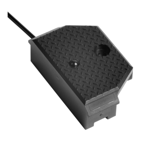
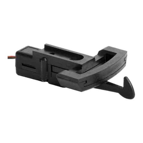
Massoth Switching Coupler 2.0 User manual

Rangierkupplung 2.0
Switching Coupler 2.0
8442010
DCC DECODER INTEGRIERT
DCC DECODER INTEGRATED
MONTAGEHINWEISE BEACHTEN
OBSERVE MOUNTING INSTRUCTIONS

2
1. Allgemeines
Die Massoth Rangierkupplung 2.0
entkuppelt einen angehängten Zug
oder Wagen bequem per Knopf-
druck. Wir empfehlen, die Produkt-
dokumentation und Warnhinweise
vor der Montage und Inbetriebnah-
me unbedingt gründlich zu lesen
und diese zu beachten. Sollten sie
zu Technik und Einbau über diese
Anleitung hinausgehende Fragen
haben, kontaktieren sie bitte die
Hotline.
1.1 Warnhinweise
•Dieses Produkt ist kein Spielzeug.
•Verbinden sie das beiliegende
Kabel mit dem Steckkontakt auf Ih-
rem Decoder oder sorgfältig nach
dem Anschlussplan (Kapitel 3)
oder für echten DCC-Betrieb direkt
mit dem Digitalgleis (Kapitel 4).
•Werden beim Anschließen Kabel
vertauscht oder Kabel verschie-
dener Funktionen (z.B. Eingänge
und Ausgänge) kurzgeschlossen,
wird die Elektronik zerstört.
•Das Bauteil darf nur an Garten-
bahnfahrzeuge mit den dort üb-
lichen Spannungen angeschlossen
werden. Ein Anschluss an andere
Geräte kann zur Zerstörung führen.
•Verwenden sie das Produkt nicht
ohne Beaufsichtigung.
1. General Information
The Massoth Switching Coupler
2.0 conveniently detaches a train
or car at the push of a button.
We recommend that you read
this product documentation and
the warnings thoroughly before
installation and operating. If you
have any questions about the
technology and installation that go
beyond these instructions, please
contact the hotline.
1.1 Warning Notes
•This product is not a toy!
•Connect the enclosed cable with
the plug contact on your decoder
or carefully according to the
connection diagram (chapter 3) or
for real DCC operation directly with
the digital track (chapter 4).
•If cables are mixed up during
connection or cables with different
functions (e.g. inputs and outputs)
are short-circuited, the electronics
will be destroyed.
•The component may only be con-
nected to garden railway vehicles
with the usual voltages there.
Connection to other devices can
lead to destruction.
•Do not use the product without
supervision.
3
1.2 Lieferumfang
•2 x Rangierkupplung 2.0 mit
steckbarem Verbindungskabel
•Schraube zur Befestigung
an LGB Fahrzeugen
•Schraube und Unterlegscheibe zur
Befestigung an PIKO Fahrzeugen
•Bedienungsanleitung
1.3 Wichtige Informationen
zur Inbetriebname
•Die Rangierkupplung besteht aus
einer Antriebs- und einem Mecha-
nikeinheit und wird aus Gründen
der Transportsicherheit komplett
montiert ausgeliefert. Für die
Montage am Fahrzeug sind beide
mit zwei Schrauben verbundenen
Teile der Rangierkupplung zu
demontieren.
•Bedingt durch das Magnetfeld des
Motors können eventuell Gleiskon-
takte ausgelöst werden.
•Wir empfehlen vorab zu prüfen, ob
das gewünschte Modell über genü-
gend Einbauplatz verfügt. Teilweise
kann eine mechanische Bearbei-
tung des Modells erforderlich
sein. Durch die riesige Vielfalt der
Modelle verschiedenster Hersteller
kann eine Montierbarkeit nicht
sichergestellt werden.
1.2 Scope of Supply
•2 x Switching Coupler 2.0 with
pluggable connection cable
•Screw for mounting
on LGB vehicles
•Screw and washer for
mounting on PIKO vehicles
•Manual
1.3 Important information
for operating
•The Switching Coupler consists of
a drive unit and a mechanical unit
and is delivered already assembled
for reasons of transport safety.
For assembly on the vehicle, both
parts of the shunting coupler
connected with two screws must
be removed.
•Duetothemagneticeldofthe
motor, track contacts may be
triggered.
•We recommend checking in
advance whether the favored
modelhassufcientinstallation
space. In some cases, mechanical
adjustment may be necessary. Due
to the huge variety of models from
different manufacturers, perfect
ttingcannotbeguaranteed.

4
2. Montage
Aus Gründen der Transportsicher-
heit wird die Rangierkupplung
vollständig montiert ausgeliefert.
2.1 Lösen Sie die zwei Schrauben
aus der Antriebseinheit und
entfernen Sie diese.
(Siehe Schritt 1 | Abb. 1)
2.2 Entfernen Sie die Antriebshein-
heit durch Abheben von der
Mechanikeinheit
(Siehe Schritt 2 | Abb. 2)
•Die Mechanikeinheit besteht durch
ihre spezielle Beschaffenheit aus
einem fest montierten Modul.
•Die Befestigungsbohrung für die
Rangierkupplungbendetsichin
der Mechanikeinheit.
•Die Rangierkupplung verfügt über
die bei Groß- und Gartenbahnen
(LGB, Piko etc.) übliche standar-
disierte Kupplungsaufnahme und
kann daher auf die Deichsel des
Drehgestells oder den Fahrzeug-
rahmen direkt montiert werden.
2.3 Die Mechanikeinheit wird übli-
cherweise mit der beiliegenden
größeren Schraube an der Kupp-
lungsaufnahme der gewünschten
Lok befestigt. Es gibt Modelle
2. Assembly
For reasons of transport safety, the
shunting coupler is delivered fully
assembled.
2.1 Loosen the two screws from the
drive unit and remove them.
(See step 1 | Fig. 1)
2.2 Remove the drive unit by lifting it
off the mechanical unit
(See step 2 | Fig. 2)
•Due to its special nature, the
mechanical unit consists of a
permanently mounted module.
•The mounting hole for the
shunting coupler is located in the
mechanical unit.
•The shunting coupler is stan-
dardizedtotgardenrailroads
(LGB, Piko, etc.) and can therefore
be mounted directly on to the
drawbar of the bogie or the vehicle
frame.
2.3 The mechanical unit is usually
attached to the coupler mount of
the desired locomotive with the
enclosed larger screw.
There are models from other

5
Abbildung 3: Montage der Entkupplermechanik an der Kupplungsaufnahme
Figure 3: Mounting the uncoupler mechanism on the coupling mount
2
Abbildung 1+2: Vorbereitung der Rangierkupplung für die Montage
Figure 1+2: Preparing the Switching Coupler for assembly
1Beide Schrauben entfernen
Remove both screws
Antriebseinheit abheben
Remove drive unit
3Mechanikeinheit an Kupp-
lungsaufnahme montieren.
(bei PIKO mit kleiner Schraube
und Unterlegscheibe)
Mounting the mechanical unit
on the coupling mount (PIKO
requires small screw and
washer)
Antriebseinheit
Drive unit
Mechanikeinheit
Mechanical unit

6
anderer Hersteller (z.B. PIKO) bei
denen die Schraubenaufnahme
kleiner ist. Verwenden Sie hier
bitte die kleine Schraube und die
Unterlegscheibe.
(Siehe Schritt 3 | Abb. 3)
2.4 Nun wird die Antriebseinheit
vorsichtig an die Mechanikeinheit
der Rangierkupplung montiert.
Dabei ist darauf zu achten, dass
die Vierkantmutter der Antriebs-
einheit vor der Montage an der
markierten Stelle sitzt. Drehen
sie dazu die Vierkantmutter
soweit heraus, dass diese mit der
Markierung uchtet. Dieser Ar-
beitsschritt ist bei jeder Montage
durchzuführen!
(Siehe Schritt 4 | Abb. 4)
2.5 Zum einfacheren Montieren und
Anschließen aber auch für War-
tungsarbeiten der Rangierkupp-
lung lässt sich das Versorgungs-
kabel von der Antriebseinheit
abziehen. Zum Entriegeln der
Kabelverbindung sind die beiden
seitlichen Rastnasen des ver-
polungssicheren Flachsteckers
einzudrücken und dieser kann
aus der Einheit herausgezogen
werden.
(Siehe Schritt 5 | Abb. 5)
manufacturers (e.g. PIKO) where
the screw slot is smaller. Please
use the small screw and washer
here.
(See step 3 | Fig. 3)
2.4 Now carefully mount the drive
unit on the mechanical unit of the
Switching Coupler. Make sure
that the square nut of the drive
unit is in the marked position
before mounting. To do this,
unscrew the square nut until it is
aligned with the marking. This
step must be done with each
assembly!
(See step 4 | Fig. 4)
2.5 The supply cable can be pulled
off the drive unit for easier
installation and connection, but
also for maintenance work on the
shunting coupler. To unlock the
cable connection, press in the
two latching lugs on the side of
the reverse-polarity at plug and
pull it out of the unit.
(See step 5 | Fig. 5)

7
Abbildung 4: Prüfen Sie, dass die Vierkantmutter an der markierten Stelle sitzt!
Figure 4: Check that the square nut is in the marked position!
Abbildung 5: Einstecken und Abziehen des Verbindungskabels
Figure 5: Insertion and removal of the connection cable
4
5
Prüfen Sie die Position der Mutter und
justieren Sie diese an der Markierung
Check the position of the square nut and
adjust ist zu the marked position

8
2.6 Achten Sie beim Zusammen-
stecken beider Einheiten, dass
die Vierkantmutter sauber in
die dafür vorgesehene Führung
in der Mechanikeinheit rutscht.
Befestigen Sie anschließend
beide Einheiten fest miteinander.
Verwenden Sie dazu die zuvor
herausgedrehten Schrauben.
(Siehe Schritt 6 | Abb. 6)
2.7 Trittstufen
Eine Druckplatte in Riffelblechop-
tik entkuppelt den Haken des
angehängten Waggons. An dieser
sind beidseitig imitierte Trittstufen
vorhanden. Diese erlauben auch
ein Entkupplen von Hand. Da diese
zum automatischen Entkuppeln
nicht notwendig sind, können sie
bei Bedarf mit einem Seiten-
schneider entfernt werden. Bei
einigen Fahrzeugmodellen kann
dies notwendig sein, da diese mit
Zurüstteilen wie beispielsweise
Bremsschläuchen kollidieren und
daher die Bewegung des Kupp-
lungshakens einschränken.
(Siehe Schritt 7 | Abb. 7)
2.6 When plugging the two units
together, make sure that the
square nut slips neatly into the
guide provided in the mechani-
cal unit. Then fasten both units
rmly together. To do this, use
the screws that were previously
taken out.
(See step 6 | Fig. 6).
2.7 Steps
A step plate in checker plate look
uncouples the hook of the attached
car. There are imitation steps on
both sides of this plate. These
also allow uncoupling by hand.
Since these are not necessary for
automatic uncoupling, they can be
removed with side cutters if neces-
sary. On some vehicle models, this
may be necessary because of them
colliding with accessory parts
such as brake hoses, and therefore
restricting the movement of the
coupling hook.
(See step 7 | Fig. 7)

9
Abbildung 6: Montieren der Antriebseinheit an die Entkupplermechanik
Figure 6: Mount the drive unit to the uncoupler mechanism
6Befestigen Sie die Antriebseinheit
an der Entkupplermechanik
Attach the drive unit to the
uncoupler mechanism
Abbildung 7: Die Trittstufen können bei Bedarf entfernt werden
Figure 7: The steps can be removed if necessary
7

10
3. Anschluss am Decoder über
Funktionsausgang (DC Modus)
Der Anschluss der Rangierkupp-
lung kann mit dem angebrach-
ten Stecker bzw. direkt an den
Anschlussklemmen des Decoders
erfolgen, die Steuerung erfolgt
hierbei über den Lokdecoder. Beim
Verlegen des Kabels ist darauf zu
achten, dass dieses nicht einge-
klemmt wird. Folgende Anschluss-
möglichkeiten sind möglich:
3.1 Anschluss mit Stecker
Bei vielen Decodern und Schnitt-
stellenplatinen kann der Stecker
des Entkupplers direkt in eine
dafür geeignete 3-polige Buchse
gesteckt werden. Eine Doppelbe-
legung mit zwei Entkupplern ist
möglich. Details können aus der
Dokumentation der betreffenden
Decoder und Schnittstellenplatinen
entnommen werden. (Abb. 8)
3. Connection to the decoder via
function output (DC mode)
The Switching Coupler can be
connected with the attached plug
or directly to the connection
terminals of the decoder. In this
case controlling is done by the
decoder. When laying the cable,
make sure that it is not jammed.
The following connection options
are possible:
3.1 Connection with plug
With many decoders and interface
boards the plug of the decoupler
can be plugged directly into a
suitable 3-pin socket. Double
assignment with two decouplers is
possible. Details can be found in
the documentation of the relevant
decoders and interface boards.
(Fig. 8)
Abbildung 8: Anschluss der Rangierkupplung am Beispiel eines eMOTION LS Sounddecoders
Figure 8: Connecting the Switching Coupler to the eMOTION LS Sound Decoder
eMOTION LS

11
Abbildung 9: Anschluss des Entkupplers mit direkter Verdrahtung
Figure 9: Connecting the Uncoupler with direct wiring
3.2 Anschluss ohne Stecker
Bei Decodern mit Schraubklem-
men oder Lötanschluss ist der
dreipolige Stecker abzuschneiden
und das Kabel entsprechend anzu-
schließen. Durch den integrierten
Gleichrichter ist die Polung der
Spannungsversorgung (DEC+ und
DEC-) nicht relevant:
• 1. Schwarz: DEC+ (Decoder +)
• 2. Schwarz: DEC- (Decoder -)
• Braun: verstärkter Funktions-
ausgang des Decoders (Open
Collector, mit mindestens 50mA
Belastbarkeit an DEC-) (Abb. 9)
3.2 Connection without a plug
For decoders with screw terminals
or solder connection, cut off the
three-pole connector and connect
the cable accordingly. Due to a
built-inrectier,thepolarityofthe
power supply (DEC+ and DEC-) is
not relevant:
• 1. Black: DEC+ (Decoder +)
• 2. Black: DEC- (Decoder -)
• Brown:ampliedfunctionoutput
of the decoder (Open collector,
with at least 50mA load capacity at
DEC-) (Fig. 9)
eMOTION XLS
Die schwarzen Leitungen können beliebig an
DEC+ und DEC- angeschlossen werden.
The black wires can be connected
to DEC+ as well as DEC- as desired.

12
3.3 Einstellungen
•Der für den Entkuppler genutzte
Funktionsausgang darf nicht
gedimmt werden.
•Die passenden Einstellungspara-
meter sind aus der Anleitung des
Decoders zu entnehmen. Dabei
kann auch der verwendete Funk-
tionsausgang auf die gewünschte
F-Taste des Steuergerätes pro-
grammiert werden.
3.3 Settings
•The function output used for the
Switching Coupler must not be
dimmed.
•The appropriate setting parameters
can be found in the decoder‘s
instructions. The function output
used can also be programmed to
the desired F key of the control
unit.

13

14
4. DCC Betriebsmodus
4.1 Anschuss am Digitalgleis
Die Rangierkupplung 2.0 kann
auch ohne einen Fahrzeug- oder
Funktionsdecoder betrieben und
dazu direkt mit dem Digitalgleis
verbunden werden. In diesem
Fall erkennt die Decodersoftware
den DCC-Betrieb und schaltet
automatisch auf diesen um. Zum
Anschluss wird bei dieser An-
schlussvariante der Mini-CT-Ste-
cker abgeschnitten und die beiden
äußeren schwarzen Kabel mit dem
4. DCC operation mode
4.1 Connection to digital track
The DCC shunting coupler can also
be operated without a vehicle or
function decoder and connected
directly to the digital track for this
purpose. In this case the decoder
software recognizes the DCC
operation and switches automati-
cally. For connection, the Mini CT
connector is cut off and the two
outer black cables are connected
to the digital track input of the
vehicle. Due to the integrated rec-
Abbildung 10: Anschluss des Entkupplers bei DCC-Betrieb mit direktem Gleisstrom
Figure 10: Connecting the Uncoupler in DCC mode with direkt track power
eMOTION XLS
X
ge ws bn gn
M+ T+ T- M-
nur 8442010
8442010 only

15
Digitalgleiseingang des Fahrzeugs
verbunden. Durch den in der
Elektronik integrierten Gleichrich-
ter muss die Polung nicht beachtet
werden. Das mittige braune Kabel
wird bei DCC-Betrieb mit direktem
Gleisanschluss nicht benötigt und
ist wegen möglicher Kurzschlüs-
se zu isolieren (abschneiden).
Die Rangierkupplung 2.0 wird
für den Digitalbetrieb mit der
Lokadresse #3 und Funktionstaste
#1 ausgeliefert. Der Entkuppler
sollte idealerweise schon vor dem
Einbau auf die jeweilige Fahr-
zeugadresse und Funktionstaste
programmiert werden. Wir raten
dazu unmittelbar danach in CV 15
die Programmiersperre zu setzen.
DetailshierzundenSieimKapitel
Programmiersperre. Weitere Pro-
grammiermöglichkeitenndensie
in der CV-Tabelle, siehe Anhang
dieser Bedienungsanleitung.
(Abb. 10)
HINWEIS: Um Funktionsstörungen
bei verschmutzten Gleisen zu
vermeiden, empfehlen wir grund-
sätzlich den Anschluss über einen
Funktionsausgang am Decoder
vorzunehmen.
tierintheelectronics,thepolarity
does not have to be regarded. The
center brown cable is not needed
for DCC operation with direct track
connection and must be insulated
(cut off) because of possible short
circuits. The Switching Coupler
2.0 is set for digital operation with
locomotive address #3 and func-
tion key #1. The switching coupler
should ideally be programmed to
the respective vehicle address and
function key before installation.
We highly recommend you to set
the programming lock in CV 15
immediately afterwards. Further
programming possibilities can
be found in the CV table, see the
appendix of this manual.
(Fig. 10)
NOTE: In order to avoid malfunc-
tions with dirty tracks, we gene-
rally recommend connecting the
Switching Coupler via a function
output on the decoder.

16
4.2 Einbau an einen Wagen
(DCC Modus)
Um die Rangierkupplung an
einem Wagen zu betreiben muss
dieser mit Metallrädern und
einer Stromabnahmemöglichkeit
ausgestattet sein. Hierzu sollten
mindestens zwei Achsen, idealer-
weise Kugellagerachsen, für eine
unterbrechungsfreie Stromüber-
tragung zum Einsatz kommen.
Die beiden schwarzen Kabel sind
dann nach Anleitung der Achsen
mit dem Gleisstrom zu verbinden,
siehe hierzu auch Ausführungen
unter Punkt 4.1. (Faltstecker im
Lieferumfang nicht enthalten)
(Abb. 11)
4.2 Installation on a car
(DCC mode)
In order to operate the switching
coupler on a car, it must be
equipped with metal wheels and
a current collection facility. For
this purpose, at least two axles,
ideally ball bearing axles, should
be used for an uninterrupted cur-
rent transmission. The two black
cables must then be connected
to the track current according to
the instructions for the axles, see
also explanations under point 4.1.
(folder plug are not included)
(Fig. 11)
Abbildung 11: Anschluss des Entkupplers bei DCC-Betrieb mit direktem Gleisstrom
Figure 11: Connecting the Uncoupler in DCC mode with direkt track power
X

17
4.3 Programmiersperre CV 15/16
Um ein versehentliches Program-
mieren zu verhindern ist in CV 15
und 16 eine Programmiersperre
realisiert. Dieses Schlüssel-Schlos-
sprinzip funktioniert wie folgt: Nur
wenn CV 15 (Schlüssel) = CV 16
(Schloss) entspricht, kann man
CVWerteverändern.IstCV15≠
CV 16, ist die Programmiersperre
aktiv. Der Wert in CV 16 sollte
nicht geändert werden. Außer man
verbaut mehrere Produkte gleicher
Art, dann muss man CV 16 ändern
um im eingebauten Zustand
einzelne Decoder ansprechen zu
können. So ist es jederzeit möglich
CV Werte auch im eingebauten
Zustand mit anderen Decodern
zu ändern. Wird CV 16 geändert,
ändert sich zeitgleich CV15 auf
den Wert von CV16. Sollte die Pro-
grammiersperre aktiv sein und Sie
wissen den Wert von CV 16 nicht
mehr, so können Sie mit CV 8 = 16
die Programmiersperre zurückset-
zen. Nach erfolgreicher Einstellung
empfehlen wir die Programmier-
sperre wieder zu setzen!
Standardwert CV 15/16 = 165
4.3 Programming lock CV 15/16
In order to prevent any accidental
programming, there is a program-
ming lock setting in CV 15 and
16. This key-lock system works
in the following way: Only if CV15
(key) equals CV16 (lock) you can
program (CV15=CV16). If CV 15
differs from CV 16, the program-
minglockisactive(CV15≠CV16).
If you install several products
of the same type, then you have
to change CV 16 to be able to
address individual decoders in the
installed state. In this way it is also
possible to change CVs with other
built-in decoders. If CV16 is chan-
ged, it automatically changes CV15
accordingly. If the programming
lock is activated and you have for-
gotten the value of CV16, you can
reset the programming lock with
CV 8 = 16. After you have success-
full programming, we suggest you
activate the programming lock!
Standard value of CV15/16 = 165

18
5. Betrieb
•Die Rangierkupplung ist so
konstruiert, dass sie sich bei der
ersten Betätigung nach der Mon-
tage selbst justiert. Anschließend
bendetsiesichindergeschlos-
senen Ausgangsposition.
•Durch betätigen der program-
mierten Funktionstaste wird der
Haken der Rangierkupplung nach
unten gefahren. Bei erneutem
Tastendruck fährt dieser wieder
nach oben.
•Beim DiMAX Navigator empfehlen
wir die entsprechende Funktions-
taste auf Momentbetrieb zu stellen
(siehe Anleitung des Navigators).
Dabei wird der Kupplungshaken
so lange nach unten gefahren wie
die entsprechende Taste gedrückt
wird. Diese Funktion ist abhängig
von der eingesetzten Digitalzen-
trale und funktioniert sicher mit
Massoth DiMAX, LGB MZS III,
PIKO G.
•Der Haken darf nur während des
Entkupplungsvorgangs abgesenkt
sein. Bei Nichtbeachtung kann die-
ser beim Überfahren von Weichen
oder anderen erhöhten Bauteilen
im Gleis beschädigt werden.
5. Operation
•The Switching Coupler is designed
in such a way that it adjusts itself
duringtherstoperationafter
assembly. It is then as closed
initial position.
•Pressing the programmed function
key moves the hook down of the
Switching Coupler. When the key
is pressed again, the hook moves
up again.
•With the DiMAX Navigator, we
recommend setting the correspon-
ding function key to momentary
operation (see Navigator manual).
In this case, the coupling hook
is moved down as long as the
corresponding button is pressed.
This function depends on the used
central station and works safely
with Massoth DiMAX, LGB MZS
III, PIKO G.
•The hook may only be lowered
during the uncoupling process.
If this is not observed, it may be
damaged when passing over swit-
ches or other elevated components
in the track.

19
•Das Entkuppeln sollte immer ohne
Last (ohne Zuglast, am besten
nach rückwärtiger Fahrt, im ent-
spannten Zustand) erfolgen.
•Lok und Wagen sind so zu rangie-
ren, dass sich die Kupplung frei
bewegen kann.
•Aus Gründen der Betriebssicher-
heit empfehlen wir im Freilandbe-
trieb den Einsatz von Kupplungen
mit beidseitigem Haken insbeson-
dere bei langen oder schweren
Zügen.
•Für eine optimale Funktion muss
die Rangierkupplung auf gleicher
Höhe wie die Kupplungen der ver-
wendeten Wagons montiert sein.
•Im Winterbetrieb ist das Ein-
dringen von Schnee und Eis zu
verhindern.
•Sollte sich der Entkupplungshaken
durch eine Stromunterbrechung
oder mechanische Blockade nicht
inderAusgangspositionbenden,
kalibriert sich die Rangierkupplung
bei der nächsten Funktionsauslö-
sung selbständig. Anschließend
bendetsiesichwiederinder
geschlossenen Ausgangsposition.
•Uncoupling should always be done
without load (without traction
load, best after backward travel, in
relaxed state).
•Locomotive and wagon are to be
so shunted that the Coupler can
move freely.
•For reasons of operational safety,
we recommend the use of coup-
lers with hooks on both sides in
open-air operation, especially for
long or heavy trains.
•For optimized function, the Swit-
ching Coupler must be mounted at
the same height as the couplers of
the used wagons.
•During winter operation, the
intrusion of snow and ice must be
prevented.
•If the uncoupling hook is not in the
initial position due to power inter-
ruption or mechanical blockage,
the Switching Coupler calibrates
itself automatically the next time
the function is triggered. It is
then back in the closed starting
position.

20
6. Wartung
Die Rangierkupplung wurde so
kontruiert, dass sie prinzipiell
verschleißfrei arbeitet und keinerlei
Wartungsarbeiten durch den
Nutzer erforderlich sind. Allerdings
können stärkere Verschmut-
zungen, z. B. durch Sand das
Material überdurchschnittlich stark
beanspruchen und auch beschädi-
gen. Daher sollte in solchen Fällen
der Entkuppler demontiert und
gereinigt werden. Die Mechani-
keinheit kann mit lauwarmem
Wasser unter Hinzugabe vom Ge-
schirrspülmittel gereinigt werden.
Die Antriebseinheit solte mit einem
feuchten Tuch abgewischt werden
und darf keinesfalls in Flüssigkeit
eingetaucht werden. Modellbahn-
übliche Öle und Fette werden
ausdrücklich nicht zum Schmieren
empfohlen!
7. Firmwareupdate
Der Decoder ist nicht updatefähig.
6. Maintenance
The Switching Coupler has been
designed in such a way that it is
basically wear-free and does not
require any maintenance by the
user. However, heavy soiling,
e.g. by sand, can over strain the
material and also damage it. In
such cases, the Coupler should be
dismantled and cleaned. The me-
chanical unit can be cleaned with
lukewarm water and dishwashing
detergent. The drive unit should be
wiped with a damp cloth and must
never be immersed in liquid. Oils
and greases commonly used for
model railways are explicitly not
recommended for lubrication!
7. Firmware Update
The decoder can not be updated.
This manual suits for next models
1
Other Massoth Toy manuals

Massoth
Massoth eMOTION Powercap maxi User manual

Massoth
Massoth 8172410 User manual

Massoth
Massoth Piko VT 11.5 TEE User manual

Massoth
Massoth LGB 20670 Track cleaning loco User manual

Massoth
Massoth 8172010 User manual

Massoth
Massoth DiMAX 1210Z User manual

Massoth
Massoth 84140 Series Manual

Massoth
Massoth LGB 20410 User manual

Massoth
Massoth LGB 2x98x Saxonian IK User manual