Maxon MCB-10A User manual

MCB-10A
40 Channel
Micro Mobile CB Radio
OWNER'S MANUAL
English/Spanish


TABLE OF CONTENTS
Product Description 1
FCC Statement 1
Performance Features 2
Package Contents 3
Controls and Functions 4
Installation Instructions 6
Mechanical Mounting 6
DC Power Supply Connection 7
Connecting the Power Cord 7
Antenna Installation 8
Antenna Tuning 9
Operating Instructions 10
Radio Communication Codes 11
CB Channel Frequency Chart 12
Troubleshooting Chart 13
Specifications 14
Optional/Replacement Accessories 15
Other Maxon Products 15
Warranty Service Instructions 16
Warranty Statement 17
Before operating your Maxon Citizens Band Radio,
read this Owner's Manual carefully. If you have a
problem, refer to the Troubleshooting Chart in this
manual before returning your radio for repairs.

TABLA DE CONTENIDO
Controles y Funciones 4
Descripción del Producto 18
Regulaciones de la FCC
(Comisión Federal de Comunicaciones) 18
Características de Funcionamiento 19
Contenido del Paquete 20
Instrucciones Para Instalación 21
Montaje Mecánico 21
Conexión de Alimentación Eléctrica de CC 22
Cómo Conectar el Cordón Eléctrico del
MCB-10A 22
Instalación de la Antena 23
La Sintonización de la Antena 24
Instrucciones de Operación 25
Tabla de Frecuencia del Canal de CB
(Banda Ciudadana) 26
Tabla de Localización y Reparación
de Averías 27
Especificaciones 28
Repuestos Accesorios Maxon/Opcionales 29
Otros Productos Maxon 29
Instrucciones Servicio de Garantía 30
Aclaración de la Garantía 31
Antes de hacer funcionar su radio de Banda Ciudadana
de Maxon lea detenidamente este Manual del
Propietario. Si tiene unproblema, refiérase a la sección
"Localización y Reparación de Averías" de este manual
antes de devolver su radio para la reparación.

1
YOU DO NOT NEED AN FCC LICENSE TO
OPERATE THIS RADIO IN THE UNITED STATES.
However, you must know and be familiar with
Part 95 of the FCC Rules in regard to Subpart D
of the Citizens Band Radio Service. (A copy is
enclosed with the unit.)
PRODUCT DESCRIPTION
Thank you for choosing the Maxon
MCB-10A Micro Mobile CB Radio.
This compact, self-contained transceiver provides
many automatic features to enhance voice clarity
and sound quality.
40 Operating channels, direct access to Emergency
Channel 9 and soft touch channel selection buttons
provide convenience to the user. A unique quick
disconnect on the radio's power cord allows the
transceiver to be easily disconnected and moved
to another vehicle or stored for safety.
Enjoy your new CB!

2
PERFORMANCE FEATURES
•All controls contained in compact, lightweight
handset
•Quick disconnect feature allows removal of
transceiver for storage or theft prevention
•Additional power/antenna connector boxes
can be purchased separately, allowing a single
MCB-10A transceiver to be used in multiple
vehicles
•Operates with maximum legal RF output power
(4 Watts)
•Communication range of up to 7 miles*
•Direct access to Emergency Channel 9
•Last channel memory recalls last channel
displayed
•Soft touch channel selection buttons
•Easy-to-read LED channel display
•Red transmit (TX) LED indicator lights during
active transmissions
•Top-mounted volume and squelch control knobs
•Built-in Automatic Gain Control (AGC) and
Automatic Noise Limiter (ANL) provide constant
sound level (from weak or strong signals) and
clear reception
•Automatic modulation control eliminates "peak"
and "valley" transmission signals
* Range will vary, depending on type of antenna used and
geography of surroundings.

3
PACKAGE CONTENTS
Main CB unit
Power/antenna connector box with antenna jack,
external speaker jack and fused DC power cord
Transceiver mounting bracket and installation
hardware
Owner'sManual
Copy of FCC Part 95, Subpart "D"
(Mobile CB antenna required for use, not included)

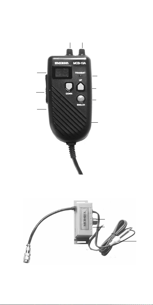
CONTROLS AND FUNCTIONS
A. Built-in Electret Condenser Microphone - Transmits
voice signals during CB operation •Micrófono
Condensador Electret Incorporado - Transmite señales
de voz durante la operación del CB
B. Push-To-Talk Bar - Permits radio transmissions • Barra
"Presione Para Hablar" (P-T-T) - Permite la transmisión
por radio
C. LED Channel Display - Identifies selected channel
• LED Imagen de Canal - Identifica el canal CB
D. Squelch Control - Reduces or removes background
noise when no signal is present on the channel • Control
Para Amortiguar Ruidos - Reduce o elimina el ruido de
fondo cuando no hay una señal presente en el canal
E. Off/On-Volume Control - Turns the radio on or off and
adjusts the listening volume • Control de Volumen - Se
usa para encender o apagar el radio y para ajustar el
volumen
F. Transmit (TX) LED Indicator - Identifies active
transmissions• Indicador LED de Transmisión
(TX)- Identifica transmisionesactivas
G. Channel Up/Down Buttons - Selects any one of the 40
available channels • Botones de Canal Arriba/Abajo -
Seleccionancualquiera de los40 canales disponibles
H. Emergency Channel 9 Button - Provides direct access
to Emergency Channel 9 •Botón de Canal 9 de
Emergencia - Provee acceso directo al Canal 9 de
Emergencia
I. Speaker - Broadcasts incoming signals • Altavoz - Emite
señalesentrantes
J. Antenna Jack - Provides connection for 50 Ohm mobile
CB antenna •Conector Para Antena - Provee conexión
para antena de CB móvil de 50 Ohm
K. External Speaker Jack - Provides connection for an
optional external speaker • Conector Para Altoparlante
Externo - Provee conexión para un altavoz externo
opcional
L. Fused 12V DC Power Cord - Provides power to radio
when wired to a vehicle's 12V DC electrical system
•Cordón Eléctrico de 12 V CC con Fusible - Provee
energía al radio cuando está conectado al sistema eléctrico
de 12 V CC de un vehículo
4

5
D E
C
B
A
F
G
H
I
L
J
K

INSTALLATION INSTRUCTIONS
Mechanical Mounting
CAUTION: Be sure the unit is mounted where it
will not interfere with the driver or impair access
to any controls necessary for the safe driving of
the vehicle. The radio's power and/or antenna
connecting cables must be routed and secured so
that they do not interfere with the operation of the
brake, accelerator or other controls. Interference
from either the CB unit or its connecting cables
may contribute to the loss of control of the vehicle.
1) Use the power/antenna connector box as a
template for marking the location of screw
holes (self-tapping screws provided).
2) Drill the necessary holes and secure the
power/antenna connector box with the
self-tapping screws.
NOTE: EXTREME CARE SHOULD BE EXERCISED
WHEN DRILLING UP INTO THE DASH to avoid
damage to in-dash electronic ignition wiring, air
bag or air bag sensors, cruise control, instruments
or accessory wiring.
3) If you choose to mount the power/antenna
connector box under the vehicle seat or at an
alternate location where self-tapping screws
cannot be used, determine the most secure
method of fastening the power/antenna
connector box. Use strong mounting tape,
plastic tie wraps, etc.
4) Use the three included screws to mount the
transceiver hanger bracket onto the vehicle's
dash.
6

5) To connect an optional external speaker, locate
the external speaker jack on the power/antenna
connector box and firmly insert the speaker
plug into the jack. The radio speaker will be
disconnected when the external speaker is
engaged.
DC Power Supply Connection
The MCB-10A is designed for 12V DC operation
in vehicles with NEGATIVE (-) electrical systems.
Most domestic and foreign-made vehicles use a
negative ground system.
NOTE: Check your vehicle's ground requirements
before you begin radio installation. If the battery
terminal marked negative (-) is connected to the
motor block of your vehicle, it is a negative ground
system.
CAUTION: DO NOT attempt to connect the
MCB-10A to a positive (+) ground vehicle. Doing
so may cause damage to the CB unit and to your
vehicle's electrical system.
Connecting the MCB-10A Power Cord
1) Make sure the off/on-volume control is in the
off position before proceeding.
2) Remove the fuse located in the MCB-10A DC
power cord. To do this, grasp each end of the
white fuse casing, push together and twist the
ends away from one another.
3) Connect the red lead wire of the DC power
cord to a positive (+) 12V DC source, either
the engine fuse block, the internal fuse box, or
directly to the positive (+) post of your battery.
7

8
Usually the internal fuse box is the most
convenient connecting point. You may wish
to connect the red lead wire to the accessory
terminal on the engine fuse block or in the
ignition switch so your CB radio will automati-
cally turn off when the ignition is disengaged,
preventing any accidental battery drainage.
4) Connect the black lead wire to the metal
chassis of the vehicle. For the best connection,
remove any paint from the grounding point. A
good, direct metal-to-metal ground is essential
for best performance.
5) Replace the fuse into the white casing on the
MCB-10A DC power cord.
Antenna Installation
Your Maxon MCB-10A requires a mobile mount
antenna for operation. Because of varying vehicle
applications, individual needs and owner cost
preferences, an antenna is not included with
your MCB-10A.
Maxon's model WTA-4WP mobile mount antenna
may be obtained from a local Maxon CB distributor,
or you may use any standard 50 Ohm mobile mount
CB antenna with a PL-259 connector.
NOTE: Please carefully follow the antenna manu-
facturer's installation instructions. Never operate
your CB radio without an antenna or with a broken
antenna cable. Doing so could cause internal
damage to the CB circuitry. Always:
•Connect the antenna securely at the antenna
receptacle of the unit.
• Mount the antenna as high on the vehicle as

9
possible - the more the antenna extends above
the roof, the better the reception will be.
•If possible, mount the antenna in the center of
the chosen surface.
•Keep the antenna cables away from noise
sources such as the ignition system, gauges, etc.
•Make sure you have a solid, metal-to-metal
ground.
Antenna Tuning
Most antennas are factory tuned. However, radio
performance can usually be improved by slightly
lengthening or shortening the antenna using a
Standing Wave Ratio (SWR) meter (not included.)
Refer to the antenna manufacturer's installation
manual for the exact tuning procedure. You can
purchase an SWR meter or have your antenna
checked by your CB Dealer's service department.

10
OPERATING INSTRUCTIONS
1) Turn the power on and adjust to a comfortable
volume level.
2) Select any one of the 40 channels by pressing
the channel up/down buttons.
3) Adjust the squelch control knob to reduce
any undesirable background noise. To do this,
select a channel where no signals are present
or wait until signals cease on your channel.
Then, rotate the squelch control knob clock-
wise to a point where the background noise
ceases.
When the squelch is set properly, the speaker will
remain quiet until a signal is received. Do not set
the squelch too high, or you will not be able to
receive weaker signals.
To Transmit: Hold the transceiver microphone area
2-3 inches from your mouth and press the push-to-
talk (P-T-T) bar located on the side of the transceiver.
Speak into the microphone slowly and in a normal
tone of voice. When transmitting, the TX LED will
glow.
To Receive: Release the push-to-talk bar.

RADIO COMMUNICATION CODES
Citizens Band radio operators have universally adopted
the "10" Code for standard questions and answers. It
enables them to communicate faster, easier and more
understandably in noisy surroundings.
The following are some of the most common codes and
their descriptions.
When using the code 10-1, you would say, "Ten one",
not "One zero dash one".
Code Description
10-1
10-2
10-3
10-4
10-5
10-6
10-7
10-8
10-9
10-10
10-11
10-12
10-13
10-16
10-17
10-18
10-19
10-20
10-21
10-22
10-23
10-24
10-25
10-26
10-27
10-28
10-29
10-30
10-32
10-33
10-34
Receiving poorly.
Receiving well.
Stop transmitting.
OK, message received.
Relay message.
Busy, stand by.
Out of service; leaving
the air.
In service, subject to call.
Repeat message.
Transmission completed,
standing by.
Talking too fast.
Visitors present.
Advise weather/
road conditions.
Make pickup at_______.
Urgent business.
Anything for us?
Nothing for you;
return to base.
My location is_______.
Call by telephone.
Report in person to_____.
Stand by.
Completed last assignment.
Can you contact?
Disregard last information.
I am moving to channel_.
Identify your station.
Time is up for contact.
Does not conform
to FCC rules.
I will give you a radio check.
Emergency traffic.
Trouble at this station.
11
Code Description
10-35 Confidential information.
10-36 Correct time is________.
10-37 Wrecker needed at ____.
10-38 Ambulance needed at__.
10-39 Your message delivered.
10-41 Please turn to channel_.
10-42 Traffic accident at______.
10-43 Traffic tie-up at________.
10-44 I have a message for you.
10-45 All units within range
report.
10-50 Break channel.
10-60 What is next message
number?
10-62 Unable to copy; use phone.
10-63 Network directed to.
10-64 Network clear.
10-65 Awaiting your next
message/assignment.
10-67 All units comply.
10-70 Fire at _______________.
10-71 Proceed with transmission
in sequence.
10-77 Negative contact.
10-81 Reserve hotel room at___.
10-82 Reserve room for_______.
10-84 My telephone number is_.
10-85 My address is_________.
10-91 Talk closer to microphone.
10-93 Check my frequency on
this channel.
10-94 Please give me a long
count.
10-99 Mission completed; all
units secure.
10-200 Police needed at_______.

Channel:
12
CB CHANNEL FREQUENCY CHART
26.965 MHz
26.975 MHz
26.985 MHz
27.005 MHz
27.015 MHz
27.025 MHz
27.035 MHz
27.055 MHz
27.065 MHz Emergency Channel
27.075 MHz
27.085 MHz
27.105 MHz
27.115 MHz
27.125 MHz
27.135 MHz
27.155 MHz
27.165 MHz
27.175 MHz
27.185 MHz Highway Channel
27.205 MHz
27.215 MHz
27.225 MHz
27.255 MHz
27.235 MHz
27.245 MHz
27.265 MHz
27.275 MHz
27.285 MHz
27.295 MHz
27.305 MHz
27.315 MHz
27.325 MHz
27.335 MHz
27.345 MHz
27.355 MHz
27.365 MHz
27.375 MHz
27.385 MHz
27.395 MHz
27.405 MHz
1
2
3
4
5
6
7
8
9
10
11
12
13
14
15
16
17
18
19
20
21
22
23
24
25
26
27
28
29
30
31
32
33
34
35
36
37
38
39
40

No sound or display
LED lights, but no sound
No voice reception
Poor reception
Unclear reception
Transmission problems
13
POSSIBLE PROBLEMS:
This Citizens Band radio
has been manufactured in
accordance with Maxon's
exacting quality control
standards. It should be
handled with reasonable
care. Avoid exposing it to
dirt or moisture.
If you experience any radio
problems, please refer to
this Troubleshooting Chart.
POSSIBLE SOLUTIONS:
Check power cable connection
Check in-line and main junction fuses
Check squelch adjustment
Check off/on-volume control
Change to active channel
Check antenna connection
Fully depress push-to-talk bar
WARNING: DO NOT ATTEMPT TO MAKE ANY
INTERNAL ADJUSTMENTS. Any internal adjustments
must be made only by qualified technical personnel.
Internal adjustments and /or modifications can lead to
illegal operation as defined by FCC Rules and Regula-
tions, Part 95. Illegal operation can result in serious
consequences.
CAUTION: The fuse included with this unit is an
important safety feature which must not be circum-
vented. Removal of this fuse or the use of a fuse rated
higher than supplied may result in overheating and/or
fire and consequential damage to the unit or vehicle.
If a replacement fuse burns out, have the unit inspected
and repaired by a qualified service technician.
TROUBLESHOOTING CHART

SPECIFICATIONS
GENERAL
CB Channels: 40
Frequency Range: 26.965 to 27.405 MHz
Frequency Control: Phase Locked Loop (P-L-L)
synthesizer
Operating Temperature
Range: -22oF to +122oF
Channel Display: Light Emitting Diode (LED)
Input Voltage: 13.8V DC nominal,
negative ground
Dimensions: 5-1/2" H x 2-5/8" W x 1-3/4" D
Weight
(transceiver w/cord): 12.8 oz.
External Speaker
(optional): 5 W input @8 Ohms with
3.5 mm plug
RECEIVER
Receiving System: AM Dual conversion
superheterodyne
Intermediate
Frequency: 1st IF: 10.695 MHz
2nd IF: 455 kHz
TRANSMITTER
RF Output Power: 4 W (Maximum FCC allowable)
Specifications are subject to change without notice.
14

OPTIONAL / REPLACEMENT
MAXON ACCESSORIES
These Maxon MCB-10A accessories are available
from your local Maxon CB distributor/retailer.
WTA-4WP Magnetic mount mobile
CB/weather antenna
MCB-20A Additionalpower/antenna
connector box
OTHER MAXON PRODUCTS
49-SX Compact, single channel 49 MHz
two-way radio offers "hands free"
operation
FRS-114 Two-way Family Radio Service radio
operates on one of 14 license-free
channels, provides up to 2-mile range
of communications (depending on
surroundings)
Maxon manufactures a full line of personal
electronic products, including handheld and
mobile CB radios, 49 MHz personal communica-
tors, Family Radio Service radios, GMRS/DOT
two-way radios, CDMA, GSM and AMPS cellular
handsets, weather monitors and a variety of
optional accessory items. Look for Maxon brand
products in quality retail stores nationwide.
15

FOR YOUR RECORDS
Purchase Date:
Purchased From:
Serial Number:
KEEP THIS INFORMATION
IN A SAFE PLACE.
WARRANTY SERVICE INSTRUCTIONS
1) Refer to the Operating Instructions section of
this Owner’s Manual for proper operation and
adjustments.
2) Refer to the basic Troubleshooting Chart for
possible solutions.
3) If the problem cannot be corrected by refer-
ence to this Owner's Manual, return the
product with proof of purchase (a sales receipt)
to the place of purchase, or call Maxon’s
Customer Service Department for assistance,
1-800-821-7848, Ext. 499.
16
Table of contents
Languages:
Other Maxon Radio manuals

Maxon
Maxon SM5102 User manual

Maxon
Maxon CM10 User manual

Maxon
Maxon HCB-40WX User manual

Maxon
Maxon SD170EX Series User manual

Maxon
Maxon SL100K User manual

Maxon
Maxon MCB-30 User manual

Maxon
Maxon SM-3000 Enduro series Instruction Manual

Maxon
Maxon SM5402 User manual

Maxon
Maxon SL-70W Series User manual

Maxon
Maxon CM10 User manual

Maxon
Maxon SP-0402 User manual

Maxon
Maxon S1 PMR446 User manual

Maxon
Maxon sm-2000 series User manual

Maxon
Maxon RSS-119 User manual

Maxon
Maxon SM-2402 User manual

Maxon
Maxon SM2102 User manual

Maxon
Maxon SP-310 User manual

Maxon
Maxon SM-2000E Series User manual

Maxon
Maxon PM200 User manual

Maxon
Maxon MBR-400 User manual