Maxon MBR-400 User manual

UHF Business Radio
User Manual

www.maxonamerica.com
2
Features ---------------------------------------------------------------------(Pg3)
Specifications --------------------------------------------------------------(Pg4)
In-Box Contents -----------------------------------------------------------(Pg5)
Description of Buttons & LCD Display--------------------------------(Pg6)
Button & Accessory Jack Operations --------------------------------(Pg7)
Installation & Removal ---------------------------------------------------(Pg8)
Charging ---------------------------------------------------------------------(Pg9)
MBR-400 Operation ---------------------------------------------------- (Pg10)
Licensing & Frequency charts ----------------------------------------(Pg15)
Safety Notes & FCC ----------------------------------------------------(Pg19)
Table of Contents

3
The Maxon MBR-400 is a simple and compact business radio perfect for restaurants, supermarkets,
retail stores, and social clubs. Pocket sized, it fits perfectly in your palm and can be used with an
earpiece (included) or loudspeaker audio. With a built-in antenna and unobtrusive swivel belt clip, you
will be able to act freely and barely notice you are wearing a radio as you communicate to the rest of
your co-workers throughout your day.
Digital (DMR TierⅠ/ Ⅱ TDMA) or Analog Mode.
16 Channels, 1 Zone
Preprogrammed w/ 16 common Jobsite frequencies in DMR Digital or choose between 89 other
Jobsite frequencies w/the Customer CPS program. Dealer CPS can program within 440-480MHz.
FCC License is required for use (Check page 15 for FCC details).
Mixed Channel Operation (Analog reception in Digital mode) **
2W (High) / .5W (Low) RF Power
Encryption Mode (AES256 optional) **
Channel Announcement **
Battery Remaining Announcement
Multiple Scan Modes, including Priority Scan
Time-Out Timer (TOT) **
Lone Worker (Safety Feature) **
Emergency / Siren (Programmable Key) **
Vibration Function
Voice recording and playback
VOX (Hands Free Transmit) **
Remote Radio Stun / Revive (Disable Target Radio) **
Built in Loudspeaker (1 Watt) & MIC
Bright and vivid TFT LCD screen
IP54 certified protected against blowing rain
Built-in Battery (DC+3.7V Li-ion / 2,000Mah); Average Battery Life: 18 Hours
** Feature enabled with Dealer-Version CPS Software
MBR
-
400
F
eatures

www.maxonamerica.com
4
MBR-400 Business Radio Specifications
General
Frequency Range
Frequency Stability
Programmable Channels
Channel Spacing
Digital Vocoder
Dimensions
Weight
Power Source
Current Drain (maximum)
440 ~480 MHz
±1.5ppm (-30 to +60℃)
16 Channels, 1 Zone
12.5KHz
AMBE++ Voice Compression Algorithm
86mm(H) x 51.5mm(W) x 22mm(D)
100g
DC +3.7V Li-ion 2,000mAH Battery (Built-in)
Receive mode, rated audio out – 420 (Audio Max)
Transmit mode – 1,200mA
Standby mode – 100mA
Receiver
Sensitivity
Squelch Sensitivity
Selectivity
Spurious and Harmonic Rejection
FM Hum and Noise
Audio Output Power
Audio Distortion
Audio Response
Input Impedance
0.25uV 12 dB SINAD
0.22uV 10dB SINAD
60dB (12.5KHz)
-36dBm(<1GHz), -30dBm(>1GHz)
40dB (12.5KHz)
1 Watt across an 8ohm load
Less than 3% at rated output
+1, -3 dB from 6dB per octave de-emphasis Characteristic from 300 ~ 3000Hz
50 ohms
Transmitter
RF Power Output
Adjacent Channel Power
Spurious and Harmonic
FM Hum and Noise
Audio Distortion
Audio Frequency Response
Output Impedance
0.5 / 2 Watt
60dB
-36dBm(<1GHz), -30dBm(>1GHz)
40dB (12.5KHz)
3% maximum with 1KHz modulation
+1, -3dB from 6dB per octave pre-emphasis Characteristic from 300 ~ 3000Hz
50ohms
Specification
s

5
MBR-400 Radio Swivel Belt Clip Single Slot Charger
C-Type Adapter w/Wall Plug Headset
Figure 1-1) MBR-400 Main Package Contents
Accessory Part Numbers:
MA-400L: Single Slot Charger
PS-M4110: USA 110V/1A Adaptor
MA-400C: USB-C Cable for Adaptor
PS-M406110: USA 110V/1A Adaptor for Multi Charger
MA-819X: Headset, “C” Style
MA-40BC: Swivel Belt Clip
MA-406L: 6 Slot Multi-Unit Charger
1. In-Box Contents (Subject to Change at Buyer’s Request)

www.maxonamerica.com
6
2. Description of Buttons & LCD Display
Figure 2-1) MBR-400 Layout

7
3. Button and Accessory Jack Operations
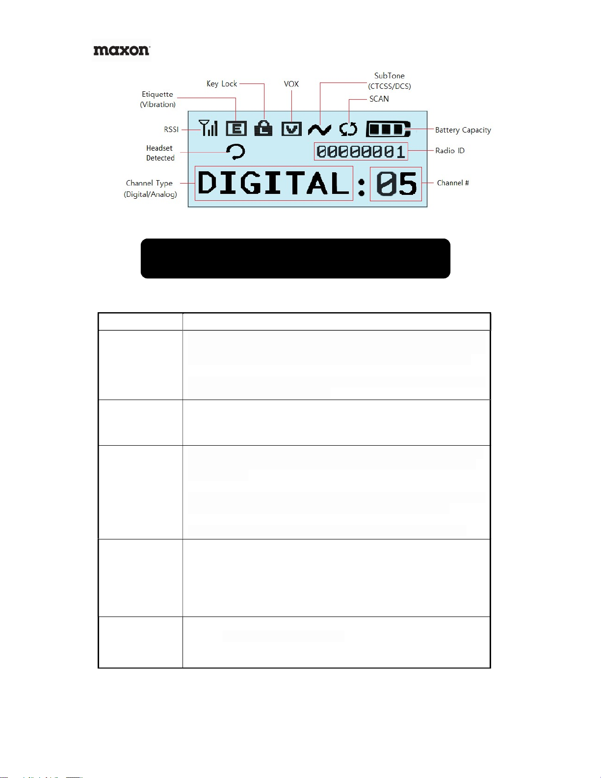
Figure 2-2) LCD Icons
Button & Jack Operation Description
Power ON/OFF &
Back out of Menus
Press & Hold the Power Button to turn on MBR-400. MAXON logo will appear on
the LCD Screen followed by a chime sound. To turn off the radio, press & hold
Power Button for 2-seconds, radio will turn off with “Goodbye” announcement
To move back out of menu selections one step at a time, Quick Press the "Power
On/Off" button for less than 2 seconds.
PTT Button
The radio transmits voice when you press and hold down the PTT button as you
speak. PTT button must be released (not pressed down) to receive any
transmissions. Please speak 5-7cm away from the MIC to transmit a clear voice.
Volume UP /
DOWN Button, Left
/ Right Menu, &
Button Unlock
If you press & hold Volume Up Button your audio volume scrolls louder one step
at a time. Pressing Volume Down decreases your volume. Volume level has a
total of 16 steps.
For selecting Menu options, press the "Volume Up/Down Button" to move your
highlighted selection either up and down or left and right within a menu.
To unlock Button/Keypad lock, press and hold Volume Down for 8 Seconds.
Menu / Select
Button
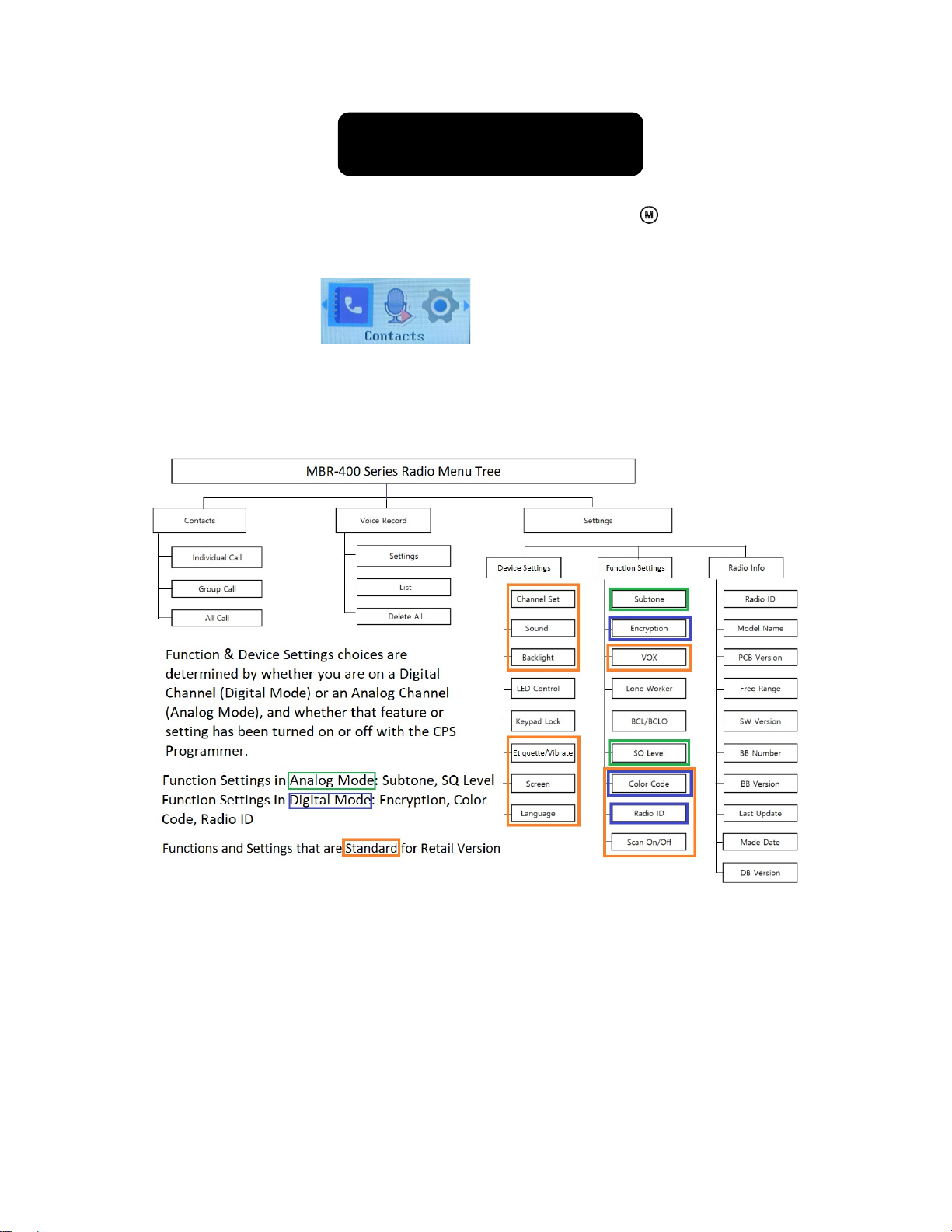
To enter your Menu screen, press the "Menu Button". Digital Mode provides
three menu options such as Contacts, Record, and Settings. Analog Mode
provides only the Settings option. Press “M” again to make a selection within a
menu.
From within the menu screen, to dismiss all menu options and return to the
welcome screen, press and hold the "Menu button" for about 2 seconds.
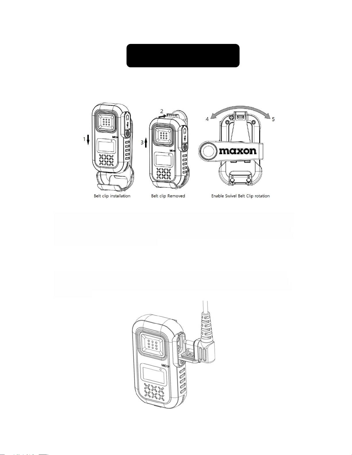
2 Pin Accessory
Jack
2 Pin Accessory / MIC Jack is used for:
1) Audio & Microphone Accessories
2) Programming Cable to set CPS Program
3) Interfacing with external devices.

www.maxonamerica.com
8
4. Installation & Removal
4.1 Belt Clip Installation and Removal
Figure 4-1) Belt Clip Installation and Removal
To attach the Swivel belt clip to MBR-400, align the belt clip to the back of MBR-400 as shown in the
figure 4-1 above and push it down to direction 1 and back against the locking tab. The clip will "click"
when locked. To remove the belt clip, push the belt clip locking tab into direction 2 and pull the belt
clip up to direction 3. In case the user wears the MBR-400 around the waist, the belt clip can turn to
direction 4 or 5 to make it more convenient.
4.2 External Accessory Connector Jack
To connect external accessories as shown in figure 4-2, open the accessory jack cover, align the
MBR-400 and the accessory, and then push-in the accessory. To remove the accessory, carefully
pull-out the accessory connector from the middle of the connector and close the accessory cover to
re-seal the jack.

9
5. Charging the Battery
Figure 4-2) Accessory Jack for Audio Accessories
MBR-400 can use the MA-400Lcharger or a USB-C Charger used by mobile phones and other
devices to charge the radio. When actively charging, the LCD screen displays charging status. A
Battery Icon on the screen will indicate full charge when charging is completed.
5.1 Charging Requirements
Low battery voltage may reduce communication coverage and also degrade performance.
Please charge the battery in case of the following:
1) When the performance has been degraded.
2) When the battery Icon blinks indicating low battery.
3) When you hear the 'warning sound' during operation.
5.2 How to Charge
MBR-400 can be charged with the in-box MA-400L charger and also most chargers using a USB C-
type cable. USB ports from a computer may not have enough power to charge a radio while the radio
is turned on.
1) Charging with MA-400L Charger
Plug the adaptor of MA-400L charger into AC110V power
outlet. Turn off the power of the MBR-400 unit and insert
the device into the charger. You do not need to take off
the belt clip, your radio is designed to be charged while
the holster is still attached (see Figure 5-1).
Figure 5-1) MBR-400 & Belt Clip charging with MA-400L Charger
2)
Charging with USB
C
-
Type Charger
Insert a USB C-type adapter into the USB C-Type Jack
as shown in figure 5-2.
When charging is completed, you see the blue battery
icon as shown below:
Figure 5-2) USB C-type charger

www.maxonamerica.com
10
6. MBR-400 Operations
MENU Screen
To enter the radio menu as displayed in Figure 6-1, press the Menu button .
If you press the menu button once you are in the Menu, it selects whatever you have highlighted.
This may move you into a more detailed menu within what you have selected.
(Digital Menu Shown)
The menu tree below shows the detail of the available selections you may have within your radio’s
menu depending on the Radio Mode you are in (Analog Channel vs Digital Channel) and what has
been turned off or on with the CPS programmer.
Figure 6-1) MBR-400 Menu Tree
☞ Note) If no menu selections are made within 25 seconds, the radio will go into Standby Mode.

11
1) Contact List (Digital Mode Only)
The Contact List provides a list of individuals, Groups, or “All Calls” to whom you can make a
Direct Call when on a Digital Channel. Contact Lists are set-up within the radio using the CPS
Software. To initiate a call, select the Contact section from the Menu. Press the Menu/Enter
button to see the list of contacts, press the ▲▼ keys to select the desired contact and press
the PTT button to initiate the call. The radio will revert to the original contact/channel after a
preset time as set by the CPS Software. When you enter in the contact menu, the applicable
icon below will be shown indicating the type of call.
Contact ICONs:
- : Individual Contact List
- : Group Contact List
- : All Contact List (Used to contact everyone on the same channel and color code)
2) Voice Record (Digital Mode Only)
This function is used to record the content of outgoing and incoming calls in digital mode only.
Up to 63 conversations/recordings can be stored with each recording limited to 150 seconds.
When the recordings exceed 63, the oldest message is overwritten. There are 3 choices
within Voice Recording Menu: Settings, Lists, and Delete All.
Settings - Allows the capability to turn the recording capability on/off.
Lists – View list of recorded messages to playback each message. To playback a message,
use the ▲▼ key to the desired message and press the Menu/Enter button to play the recording.
Delete All – Provides the capability to delete stored recordings. You cannot delete messages
one at a time. To delete recordings, select Delete All from within the Voice Recording menu by
pressing the menu/enter button, the question to Delete All? will appear with the word “Yes”.
Press the menu/enter button to delete all messages. If you choose not to delete the messages,
press the return button to exit out.
3) Settings
The Settings menu provides three options; Device Settings, Function Settings, and Radio Info.
**Setting/Function can be turned on / adjusted once the setting is activated via CPS program.
1. Device Settings: Adjust Channel, Sound, Backlight, Etiquette (Vibrate), Screen, Language,
Status LED** & Button Lock**.
2. Function Settings: Digital Channels (Digital Mode) and Analog Channels (Analog Mode)
provide different options for the radio. Digital Mode provides settings for Color Code and Radio
ID, & Encryption**, Analog Mode provides settings for Sub Tone & SQ level. VOX, Scan On/Off
Lone Worker**, and BCL/BCLO** are provided in common for both Analog and Digital.
3. Radio Info: Provides General & Technical information about your radio.

www.maxonamerica.com
12
(1) Device Settings (** Setting not available in Retail version, Add w/CPS Software)
① Channel Set
‘Channel Set’ allows you to select a preprogrammed channel to make a call. Channels can be
programmed with the CPS Software.
② Sound
'Sound' allows you to adjust sounds of the radio. In the volume menu, sound can be adjusted
in four different modes; Off, Soft, Medium, and Loud. In the Call Tone menu, call-related
sound transmitted / received can be set to either On / Off.
③ Backlight
‘Backlight’ function allows you to switch the LCD’s backlight to be “ON/OFF” or “Timed”.
Duration of “Timed” option can be programmed using CPS Software.
④ LED Control**
‘LED Control’ allows you to enable or disable the radio status LED. The LED status can be set
via CPS Software.
⑤ Keypad Lock**
‘Keypad Lock’ locks the keypad to prohibit any accidental press of keys and buttons. When
keypad lock is enabled, all keys/buttons are locked except PTT button and power ON/OFF
button. When any of the side keys are pressed, the display shows “Press Unlock button”. If a
key has been assigned to unlock the keypad, the radio resumes normal operation. When no
buttons are pressed for the pre-determined time, keypad lock is automatically enabled. If no
keys are assigned to unlock the keypad, the down button can be pressed for 8 seconds
to disable it.
⑥ Etiquette (Vibrate)
‘Etiquette’ informs you of an incoming call by vibration without making a reception sound.
When you want to hear the voice of the caller, momentarily press the PTT button. When there
is no button input by the user for 30 seconds after the call, it is switched back to etiquette
mode (vibration mode).
⑦ Screen Settings
Screen Settings contains two settings options, Screen Type and Screen Kind. Screen Type
provides three channel formats to be displayed. Screen Kind provides two background
settings. A Bright Screen and a Dark Screen. Selecting Bright Screen is a light blue
background with black lettering. The Dark Screen is black background with white lettering.
The 3 Screen Types are shown below. The information displayed can be set via CPS
Software. Contact your Authorized Dealer for further information

13
Figure 6-2) MBR-400 Screen Setting View
⑧ Language
This function is to select the language (English or Spanish) for the menus.
(2) Function Settings (** Function not activated in Retail version; Enable w/CPS SW)
① Subtone (Analog Mode Only)
Subtone functions only on Analog Channel. A user may set three subtones of
CTCSS/DCS/Reverse DCS. Feature is selectable with both the CPS and via the radio itself.
② Encryption** (Digital Mode Only)
This function is to encrypt transmission and reception voice.
Voice Encryption function can be set for each channel on all digital channels.
The voice encryption code is set in the CPS program and provides 128/192/256-bit encryption
③ VOX
VOX function allows a user to transmit voice without pressing the PTT button.
VOX sensitivity level is adjusted from 1 to 5 with 1 being the LEAST sensitive; you will need to
speak loudly to activate VOX on setting 1.
④ Lone Worker** (Digital Mode Only)
Used as a safety feature to send an alert to others if you do not use your radio within a
predetermined amount of time that is set in the menu.
⑤ BCL/BCLO**
This function prevents interference when the channel is busy.
Digital Mode Only
BCL On: If the current channel is busy, the transmission is prohibited.
Analog Mode
BCL On & BCLO Off: If the current channel is busy, transmitting is prohibited.
BCL On & BCLO On: Transmitting occurs when it matches the received tone.
⑥ Squelch Level** (Analog Mode only)
This function allows users to change squelch levels of Open, 1,2,3,4, or Tight. Tightening the

www.maxonamerica.com
14
squelch reduces the chance of the audio unmuting due to RF interference.
⑦ Color Code (Digital Mode Only)
Color Codes are used in DMR to help separate radios on the same frequency & is selectable
with both the CPS program and via the radio itself. The radio setting allows you to change
your color code value between 0 and 15.
Press MENU then go to Settings/Function Settings/Color Code. You should see Color
Codes of 0 ~ 15. Scroll to the desired Color Code and press the MENU key to store it.
The POWER button is used as a back one step button. 4 button presses will escape
back to the channel number or a long press of the menu button will exit the menu.
⑧ Radio ID (Digital Mode Only)
Radio ID is assigned to each radio to identify the operator of the radio. The corresponding ID
number and name will appear on the receiving radio. The OWN ID can be set-up in the CPS
software or via the radio itself
Press MENU then go to Settings/Function Settings/Radio ID. You should see a Radio
ID of 00000001. Press MENU again to begin the change. UP/DOWN buttons change
the value while the MENU button advances to the next number. When you get to the
end press the MENU button again to save the setting. POWER button is used as a
back one step button. 4 button presses or a long press of the power button will exit
back to the standby screen.
⑨ Scan On/Off
This function allows user to turn scan on/off for a scan list that is programmed via CPS
Software. User can scan digital and analog channels to find a channel in use.
(3) Radio Info
Radio Info contains all the general & technical information of the radio such as; Radio ID,
Mode Name, PCB Version, Frequency Range, SW Version, BB Number, BB Version, Last
Update, Made Date and DB Version.

15
7. Licensing & Frequency Charts
FCC LICENSING INFORMATION
INTERFERENCE INFORMATION
This device complies with Parts 90 and 15 of the FCC Rules. Operation is subject to the condition that this device does not cause
harmful Interference. MBR-400 Series radios operate on radio frequencies regulated by the Federal Communications Commission
(FCC). To transmit on these frequencies, you are required to have a license issued by the FCC. Application is made available on
FCC Form 601 and Schedules D, H, and Remittance Form 159.
To obtain these FCC forms, request document 000601 which includes all forms and instructions. If you wish to have the document
faxed, mailed or have questions, use the following contact information to contact the FCC.
1-202-418-0177
1-800-418-FORM (1-800-418-3676)
1-888-CALL-FCC (1-888-225-5322)
Or: http://www.fcc.gov
7.1 UHF Frequency charts
MBR-400’s first 16 channels are preprogrammed out of the box with the first 16 channels
listed below.
The CPS Programmer for the MBR-400 is preprogrammed with all the frequencies listed
below and can be used to change the contents of the channels of your radio and set your
radio to digital or analog mode.

www.maxonamerica.com
16

17

www.maxonamerica.com
18
7.2 CTCSS and DCS Code Tables (for use with CPS program)

19
8. Precautions
8.1 Precautions for safe operation
Don’t use other manufacturer’s accessories (such as rechargeable battery,
adaptor, external speaker microphone and earphone, etc.). Unknown or
unauthorized accessories may damage the radio and void the warranty.
Don’t disassemble or rearrange the parts and accessories of your radio.
The disassembly or reorganization of your radio is punishable by law and
can cause damage to the radio that will not be covered by the warranty.
Don’t use frequencies you do not have a permit for.
Avoid excessive shock to the Radio. Don’t place the radio in direct
sunlight or in extreme high temperature. Battery damage can occur in
those environments. Do not disassemble or damage the battery pack.
8.2 Do not use the radio where prohibited
Your radio emits a strong electronic wave which may have an effect on the operation of other
equipment and can also be affected by those other devices.
Please turn off the radio before boarding an airplane. If you want to use
the radio during flight, please adhere to the aircraft’s rules.
If using the radio in an area where medical equipment is being used,
please get permission from the staff before use to prevent interference
issues.
Be careful when using your radio in a place where computers or other
electronic devices are being used because the strong electronic waves
from the radio can affect this equipment.

www.maxonamerica.com
20
9. Safety Notes & FCC
9.1 Safety Notes & FCC
Please make sure to read the followings above for safe and effective use of the radio.
• Please keep the Radio away at least 1 inch from the body.
• Do not touch antenna if it is damaged. Risk of skin burn can occur if the outside surface of antenna is
stripped out.
• Please be careful when putting the battery in a pocket or a bag. If you contact a conductive metal to a
battery terminal, there is a heat and fire risk to your radio.
• Please don’t listen to the radio at a high-volume level when using earphones. Loud volume may have a
lasting bad effect on your hearing.
• It is recommended to adjust the volume step by step to the level you want after you set the radio volume
of the radio at a low level.
• Please don’t remove or replace or charge or discharge the battery in a hazard area where sparks could
cause an electrical fire.
• Turn off the radio in areas where there is a strong electromagnetic force.
Table of contents
Other Maxon Radio manuals

Maxon
Maxon TJ-3000 Series User manual

Maxon
Maxon SM-2000E Series User manual

Maxon
Maxon CM10 User manual

Maxon
Maxon SD170EX Series User manual

Maxon
Maxon TSD-4000 Series User manual

Maxon
Maxon SM-3000 Enduro series Instruction Manual

Maxon
Maxon MBR-400 User manual

Maxon
Maxon PM100 User manual

Maxon
Maxon SP-120 Series User manual

Maxon
Maxon SL-70W Series User manual