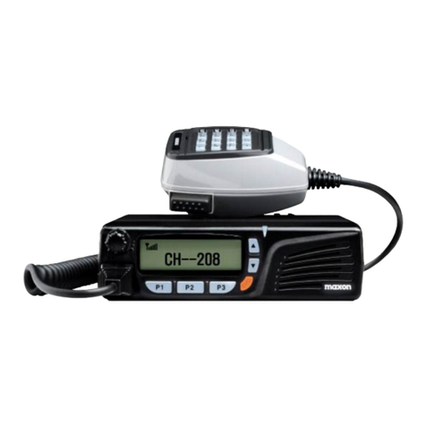
Maxon SM-2000E Series User manual

32
SM-2000E Series User Manual
"Professional Mobile Radio"
TecNet International Inc.
11535 W. 83rd Terrace
Lenexa, KS 66214
Tel.913-859-9515
Fax.913-859-9550
E-mail: [email protected]
www.tecnetusa.com

21
TABLE OF CONTENTS
Safety Information-----------------------------------------------------------1
Table of Contents------------------------------------------------------------2
Specification------------------------------------------------------------------3
About Your SM-2000E Radio-----------------------------------3
Unpacking---------------------------------------------------------------------4
Installation---------------------------------------------------------------------5
SM-2000E Features & Description--------------------------------------6
Product Description------------------------------------------------6
Front panel--------------------------------------------------------------------7
Front panel layout--------------------------------------------------7
Rear panel--------------------------------------------------------------------8
Rear panel layout--------------------------------------------------8
Rear 15 way sub Dtype pin-out---------------------------------8
LCD Display------------------------------------------------------------------9
Basic Radio Operation----------------------------------------------------10
On/Off Volume Control-------------------------------------------10
Power On Sequence----------------------------------------------10
Basic Radio Operation Receiving--------------------------------------11
Basic Radio Operation Transmitting----------------------------------12
Basic Programmable features------------------------------------------15
Beep On/Off Mode-------------------------------------------------15
Squelch Options---------------------------------------------------15
CTCSS ------------------------------------------------------------15
DCS-------------------------------------------------------------------16
Squelch Defeat (Monitor) operation---------------------------16
Cloning------------------------------------------------------------------------17
Scanning---------------------------------------------------------------------18
Emergency Call------------------------------------------------------------23
Selcall code selection-----------------------------------------------------24
Status and Error Messages---------------------------------------------25
Service Information--------------------------------------------------------26
SAFETY/ WARNINGS
Safety Information
Please read the following before connecting the radio to a DC power supply.
1. WARNING! NEVER connect the transceiver to an AC outlet. This may pose
a fire hazard or result in an electric shock.
2. WARNING! NEVER operate the radio transmitter without a suitable artificial
load or antenna connected.
3. WARNING! NEVER connect the transceiver to a power source of more than
16V DC such as a 24V battery.
4. WARNING! NEVER place the transceiver where normal operation of the
vehicle may be hindered or where it could cause bodily injury.
5. WARNING! NEVER expose the transceiver to rain, snow or any liquids.
6. CAUTION do not cut the DC power cable between the DC Plug and fuse holder.
If an incorrect connection is made after cutting, the transceiver may be
damaged.
7. CAUTION The transceiver will become hot when operating continuously for
long periods.
8. CAUTION never modify a radio or accessory except as instructed in the service
manual, engineering bulletins or formal communication as this may invalidate
any warranty, guarantee or type approval.
9. AVOID using or placing the transceiver in areas with temperatures below -
30℃or above +60°C or in areas subject to direct sunlight, such as the
dashboard.
10. AVOID operating the transceiver without running the vehicle engine. The
vehicle battery will quickly run out if the transceiver transmits while the
vehicle engine is OFF.
11. AVOID placing the transceiver in excessively dusty environments.
12. AVOID the use of chemical agents such as benzene or alcohol when
cleaning, as they can damage the transceiver surfaces.
13. ALWAYS USE original Maxon microphones. 3rd party microphones have
different pin assignments and may damage the transceiver.
14. DO NOT operate this equipment in environments containing explosive
materials or vapors.
WARNING
Government law restricts the operation of unlicensed radio transmitters within
g
overnment controlled territories.
Ille
g
al operation is punishable b
y
f
ine or imprisonment or both.
R
e
f
er service to quali
f
ied technicians onl
y
.
WARNING
EXPLOSIVE ATMOSPHERES (GASES, DUST, FUMES, etc.)
Shut Off the transceiver while refueling or while parked in gasoline service stations.
Do not carry spare containers in the trunk of your vehicle if your transceiver is mounted in the
trunk area.
WARNING
INJURY FROM RADIO FREQUENCY TRANSMISSIONS
Do not operate your transceiver when somebody is either touching the antenna or standing
within two to three feet of it to avoid the possibility of radio frequency burns or related physical
injury.

43
2. Specification 3. Unpacking
About Your SM-2000E Radio
Maxon's SM-2000E Series radio features 99 channels. Operation and functions of
this radio are outlined in this manual.
We urge you to thoroughly read this manual before operating the radio.
The application of some of the functions described in this manual are determined by the system
you use. Your Maxon Dealer will program your radio so that you have the greatest number of
functions possible relative to your needs. The below specifaction outlines the approximation
results from in-house testing and may vary slightly from radio to radio.
General Performance certification
R&TTE Directive 1999/5/EC
FCC/IC
EMC Directive 89/336/EEC
LV Directive 73/23/EEC EN 60950-1
72/245 EC as assembled by 2004/104/EC
Frequency Band 136-174 MHz VHF
400-470 MHz UHF
Modulation type F3E/G3E
Channels 99
Channel Bandwidth 12.5 kHz
PLL Step 2.5 kHz, 5kHz, 6.25kHz
Input power supply 13.2Vdc nominal
15.6Vdc maximum (extreme)
10.8Vdc minimum (extreme)
Antenna Impedance 50 ohm
Operating Temps -30℃ to +60℃ nominal
Current consumption
OFF <10μA
Standby (muted) <220mA
Unmuted with 25% AF power <350mA
Unmuted with 50% AF power <450mA
Unmuted with 100% AF power <1000mA
Transmit @ 5W RF output <2.5A
Transmit @ 25W RF output <7.0A
Intermediate frequencies 46.35MHz First I.F.
450kHz Second I.F.
Frequency stability +/- 2.5ppm
Receive
Sensitivity 0.25 μV @ 12 dB SINAD
Adjacent Channel 60 dB
Intermod Reject 65 dB
Spurious Response 65 dB
Audio Power Out 6 W int., (Internal 8Ω speaker)
Audio Distortion <=5%
Transmit
Output Power 5/25 W
Frequency Stability 2.5 ppm
Spurious & Harm. -36 dBm (<1 GHz), -30 dBM (>1 GHz)
Audio Distortion <3% typical
Adjacent Ch Power >-60 dBc
1. 1 x Main mounting bracket
2. 2 x Thumb wheel screws
3. 1 x Microphone bracket
4. 2 x M3 x 6mm Mic bracket Screw
5. 2 x M3 Mic bracket Washers
6. 2 x M3 Mic bracket Spring Washers
7. 2 x M5 x 11mm main bracket screws
8. 2 x M5 Washers
9. 2 x M5 Spring Washers
10. 4 x Rubber feet
11. 1 x power lead with 10 amp fuse.
1
2
3
4
5
6
7
8
9
10
11
Installation Kit contents

65
Installation
+
+
RED:
RED:
BLACK:
BLACK:
Antenna socket
The antenna connector is a SO-239
"M" type with 50 ohm impedance
at this point. Please seek advice
from your dealer in reference to the
correct type of antenna to suit your
particular requirements
15 Sub D-Type
External interface connector
See page 8 for pin out
RF Radiation
can cause
serious burns
and injury
Accessory Socket
The external accessory socket can be
used for additional audio devices.
An external speaker can be fitted and
used as a PA device or just to increase
audio output.
Installation of VHF and UHF radio equipment, antennas and power supplies
should only be carried out by an engineer qualified in the relevant fields.
Keep all antennas a good distance away from all areas of human activity
and use a good ground plane. Use quality equipment for installations i.e.
connectors, cable and power supplies.To minimise electric shock and
RF leakage never modify a radio or accessory, except as instructed in the
Service Manual.
SM-2000E Features & Description
Programmable feature list
High/Low power 25W or 5W Programmable
Monitor button
Programmable 12.5/25 KHz channel spacing
Wideband 400-470 MHz 136-174 MHz
Busy channel lock-out
Mark Idle
Chanel groups
Time out timer
Penalty timer
Key and status beeps
Covert mode
Master Mute button
Hook switch
Hook scan
Back light and color control settings
Electronic Serial number (read only)
Programmer reads Firmware version
Password protected
99 Programmable channels
Stun and revive
10 User defined CTCSS tones
CTCSS/DCS/IDCS tone Signalling
User adjustable squelch
5 tone selective calling
5 tone acknowledgement
ANI (Automatic Number Identification)
Start up definable logo
40 Encode and decode Selcall addresses
Key lock
DTMF
DTMF side tone
PTT ID
Emergency Call
Group/channel name or number
4 x programmable keys short & long press
Memory channels
Scanning Alignment
All of the following adjustable RF
parameters can be electronically adjusted.
RF Power high and low, RX1 front end, RX2
front end, TCXO, Modulation deviation and
CTCSS deviation.
Please speak with your dealer if this is a
requirement.
* Channel scan
* Priority channel scan
* Scan list edit
* Priority channel edit
* Power on scan
* Nuisance delete
Product Description
The SM-2000E is a fully featured mobile radio that has been developed as a worldwide product.
The SM-2000E is a DTMF, Selcall and mobile radio with a 99 channel capability. The radio is
programmable for output power, channel spacing, and a range of other features.
The radio is packed full of sophisticated user and system features which allow the radio to be tailored
to meet the requirements of most radio networks today. All the features described are made available
thanks to the latest reliable, but functionally rich, software that controls each SM-2000E mobile.
This means that all features described are available without the need to fit expensive and time
consuming option boards.Most of the features or options described are activated in the radio
as programmable parameters; please contact your dealer for full details on these options.
The four buttons located on the bottom left-hand side of the radio under the LCD, are described
as programmable. These four buttons (P1, P2, P3 and P4) have a short and long press and
can be used for various pre- programmed features, following Monitor, Power H/L, Scan, DTMF,
Key lock, Selcall, Scan, Open Close, and Light. The range conforms to R&TTE Directive.
The unit meets the R&TTE Directive ETS 300.086 2001 and all FCC requirements.
DC Power Supply
The supply voltage for the
SM-2000E is 12V – 13.8 Volts DC.
Do not connect the polarity
incorrectly as this may cause
permanent damage.
Note: A DC to DC Converter maybe
required to convert 24V to 12V
for some installations.
10 Amp fuse holder and fuse,
check fuse is present before fitting radio.
WARNING

87
Rear Panel
Front Panel
1
1
2
3
4
5
6
7
2 3 4
567
No.
Name Description
Volume Control Knob
Power ON/OFF, Volume Control
Function LCD
LCD displays the following.
- Information about the current channel
- TX/RX Status
- Messages: see the LCD description page 10
- Encode and decode Selcall codes
- Power settings
- Error messages
- ANI
UP/DOWN Keys These keys are used for channel selection.
LED
Tri colored LED Indicator
- TX/RX and busy Status
> Transmit = Red
> Received signal = Green
> Channel is busy = Orange
- Status indicator
Microphone Connector
Connect the microphone to the RJ45 8 pin connector.
This is also used for programming and cloning.
Programmable Keys You can assign functions to these keys in the
programmer.
Intenal Speaker Audio is produced through the internal speaker.
12 3 4
5
2
3
4
5
Antenna lead should be fitted here, the connector type is
SO-239 M type. The impedance at this point is 50Ω
15 Way Sub D-type
GPS Antenna Port (Optional)
DC power lead
Accessory Socket
1
No.
Name Description
SO-239 Antenna Connector
15 way Sub D-type External interface. Please see
table below for pin-outs.
There is an aerial port available if a GPS antenna is required.
The port is currently sealed with a rubber grommet.
12 ~ 13.8 Volts are required to power the SM-2000E.
Any audio device can be fitted here e.g. external speaker.
15 pin-out D-type
Pin Allocation name Description Specification
1RSSI DC power output 0.6 - 1.4V
2IGN Ignition signal input Power ON: ↑8V
Power Off:↓6V
LK20 is selection
LSP Low speed data LK10 is selection
3EXT/OUTPUT Programmable
4AF_OUT Audio output 500mV
5EXT_MIC Audio input 5KΩ
6TXD FCN1 TX Serial data 3.3 TTL
7RXD FCN2 RX Serial data 3.3 TTL
8EXT_PTT External PTT 3.3V (H) PTT Off
0V (L) PTT On
9F_AUDIO IF IC Output 100mW
10 COR/COS Squelch output SQ off:0V SQ on:3.3V
11 EXT/INPUT Programmable High impedance
12 DC+5V DC Power Supply DC+5V Max 100mA
13 EXT/OUTPUT Programmable
14 BEEP EXT Beep signal input
15 GND Ground Ground

109
Basic Radio OperationLCD Display
2 3 4 51
7
6
8 9 10 11
No. Icon FunctionName Description
TX
This icon appears when the
transceiver transmits.
Low TX Power
Channel
This icon appears when the TX
power of the current channel is low.
Call alarm
This icon blinks when the
transceiver receives a call.
Sub-audio Tone
Channel
This icon appears when the
current channel has sub-audio
tone (CTCSS, DCS, and IDCS) option.
Channel Number
The current channel number
is displayed.
Text Display
Display information such as
channel name, group number,
menu, ANI, etc.
Scroll
This icon blinks if the length of
text is more than 6 characters.
Busy
This icon appears when the
transceiver receives signals.
Priority Channel
This icon appears if the current
channel is programmed with priority scan.
Scan
This Icon blinks when
the radio is scanning.
Scan List
This icon appears if the current
channel is registered in scan list.
The LCD can display Alpha numeric characters and can be
scrolled using the programmable (P1- P4) keys. Selcall numeric codes, stun
and revive and error messages can also be displayed.
1
2
3
4
5
6
7
8
9
10
11
Before beginning any operation of the product please ensure installation has been carried out by a
qualified engineer. Make sure connections - power, antenna and microphone have been fitted correctly.
Many of the functions set out below are controllable via the PC programmer, please contact to your dealer
for more information.
O
On
/O
/O
ff V
ff Volu
me
me
Co
Con
tr
trol
Turn the radio on by rotating the off/on/volume control clockwise. You will hear a click and the radio
self-test alert tones (if enabled via dealer programming). If there is an error the LCD will display the
error code. Increase the radio volume by continuing the clockwise rotation.To turn the radio off, rotate
the control counter-clockwise until a click is heard.
Po
we
wer
o
on
S
Sequence
1) Initialisation
Initialisation is performed when the transceiver is turned on. Error message will be displayed
if any errors occur.
Error Code Radio has no channels programmed
2) Power ON Beep (if programmed)
Beep sounds after the initialisation process has finished (depends on beep option).
3) Start Logo (if programmed)
Display the text for one second when the transceiver is turned on. All segments and icons
will be displayed if there is no programmed start logo.
4) Password Check (if programmed)
The password function requires the user to know the preprogrammed numeric code. The transeiver
is inoperable until the password has been entered. The password consists of 1 to 5 numerical
digits each digit can be 0-9 in range.
* Key assignment for inputting password.
There is no limit to the amount of attempts a user can make for inputting the password.
The radio is ready to use after correct number is entered.
Note: if password is forgotten then the radio will need re-programming to reset the Password.
Delete
Change Digit Next Confirm

1211
Basic Radio Operation - TransmittingBasic Radio Operation - Receiving
Channels
The SM-2000E Series radio can store up to 99 channels within the same frequency band (UHF 400~
470MHz VHF 136~174 MHz).These channels can be selected by using the ▼▲ (up/down) keys.
1) Busy
When receiving a call, the icon appears. Adjust the volume level to a comfortable listening
level. Mute and unmute condition is determined by the squelch level and current channel's
tone option.
2) Correct Call
This applies to channels that have sub-audio tone option (CTCSS, DCS, IDCS) programmed.
Correct call means the received tone option is equal with the current channel option.
The transceiver goes to unmute condition if the current channel is in correct call status, where
the transceiver matches both carrier and correct CTCSS or DCS codes.
3) Monitor Function
Release the squelch and tone option to check whether you can use current channel.
Push 'MONITOR' KEY(ON/OFF) to use this function.
4) Channel Selection
To change the channel, push ▼▲(up/down). The empty channels (not programmed) will be skipped
automatically when channels are changed. Push and hold ▼▲ (up/down) to change channels rapidly.
5) Group Selection
To change the current group, you can assign 'GROUP ' functions to
'PROGRAMMABLE KEYS'. The empty groups (not programmed) will be skipped automatically when
groups are changed. Push and hold the programmed key to change groups rapidly. LCD shows the
name of the current group for 1 second if the group is changed.
6) Options
Squelch Level
GROUP UP KEY
1 GROUP 1 CHANNEL
1 SECOND LATER
Squelch level is adjustable through the programmer. If signals are weak, you can
decrease squelch level. You can increase the squelch level when unwanted signals exist.
1) PTT Key (Push To Talk)
Hold microphone approximately 3 inches distance from your mouth.
Push and hold PTT key and then speak into the microphone.
The PTT can also be used to transmit PTT ID codes, 5 tone Selcall, and
DTMF codes. Select DTMF/Selcall code from Selcall List and push PTT key.
Refer to individual tone section for more information.
2) Call Key
If you have assigned a CALL function to the 'Programmable keys' to transmit codes,
select 5-tone code from Selcall List and push the CALL key.
Please refer to "Selective" section.
3) Talk Around
This function allows users to communicate with others directly when
repeater frequencies are programmed i.e. when RX and TX frequencies are
different. When Talk Around is selected from the menu the receiving frequency
is then used for both transmitting and receiving. To use this function, assign
' Talk Around ' function to 'Programmable keys' in programmer. This function will be cancelled
automatically when the channel is changed.
4) Transmit Inhibit
Time out Timer (TOT)
This function is to prevent continuous transmitting over that of the specified time.
You can set this option through the programmer. Transmitting is inhibited if you keep
transmitting more than the programmed time. LCD shows 'TOT' for a few seconds.
Function
Function
Range
Range
Step
Step
Default
Default
TOT ON/OFF
TOT ON/OFF
ON/OFF OFF -
10~990 10 10
TOT time
TOT time

1413
Basic Radio Operation - Transmitting Basic Radio Operation - Transmitting
Function Range StepDefault
PT ON/OFF
PT ON/OFF
ON/OFF OFF -
5~75 5 5
PT time
Position Description
BOT
BOT
Begin of Transmission
End of Transmission
EOT
5) Penalty Timer
You can not transmit during penalty time if transmitting is inhibited by 'TOT' function.
LCD will show 'P-T' if you try to transmit within the specified time.
6) Busy Channel Lock Out (BCLO)
This function is to prevent transmitting when current channel is in busy status. LCD shows 'BCLO'
if you try to transmit when the current is busy.
B
Busy
Ch
Channel
L
Lockou
t - O
t - ON
: upon PTT being pressed, if carrier is present, the radio will not transmit
and an audible alert tone will be heard.
B
Busy
Ch
Channel
L
Lockou
t - O
t - OFF
: upon PTT being pressed, the radio transmits regardless of the
presence of carrier.
7) Marked Idle
This option allows transmitting during correct call status even if BCLO option is activated.
Re
Receive
o
only
Ch
Channel
Transmitting is inhibited if the current channel is a receiving only channel. You can create
a receiving only channel through the programmer. LCD shows 'RX-CH' if you try to transmit
in the receiving only channel.
8) TX Power
You can set transmitting power to low or high in each channel. The 'LOW' icon appears
if the current channel is set to low power. The power can be switched by the user from
High to Low by pressing a pre-programmed power key (P1-P4).
9) TX Delay
TX delay eliminates squelch tails associated with CTCSS tone transmissions, by removing the
CTCSS tone from the end of a transmission for approximately 200ms before the carrier is dropped.
10) Microphone Hook
11) PTT ID
This is a PC programmable function. Turned OFF, the user is not required to ground microphone
button on to the Mic hanger. All decode and scan functions remain the same. Turned ON, the user
is required to ground the microphone hook. When microphone is removed from ground all tone
decode functions are disabled, scan functions are programmable as on or off with microphone
removed from hook. Default is off with scan disabled.
You can transmit the PTT ID when you push PTT ID key. PTT ID is progammable up to
5 digits. The following table shows the options for PTT ID.

1615
Basic Programmable features Basic Programmable features
1) Beep On/Off Mode
All Beep tones can be globally enabled or disabled via the radio controls depending how
the radio is programmed.
2) Squelch Options
The radio supports 3 kinds of Squelch options. A different Squelch option can be applied
to each channel. Sub Audible Tone (SAT) codes are made up from frequencies which are
below 300Hz. These frequencies are lower than the voice audio band. The two most common
forms of SAT codes are CTCSS, Continuous Tone Coded Squelch System, and DCS, Digitally
Coded Squelch.
CTCSS / DCS information may be added to speech during transmission. A receiving radio can
then be programmed to react according to which tones or codes are being sent by
a transmitting radio.The SM-2000E series radios are capable of generating all 38 standard
CTCSS tones and can also generate the 104 standard DCS codes and 104 inverted DCS codes.
CTCSS
CTCSS
38 kinds of TIA/EIA Standard CTCSS tones and 12 non-standard tones can be set up.10 user
defined tones can be added separately. All tones can be set up using the PC Programmer.
TX
O
Opera
ti
tion
: If PTT key is pressed, the radio transmits a programmed CTCSS tone.
RX
RX
O
Opera
ti
tion
: If CTCSS tone is detected, the radio status is changed from Busy to Correct Call.
If the CTCSS Tone is not detected, the radio would stay in busy mode or change from
Correct Call to Busy mode.
1 67.0 14 107.2 27 167.9 40 159.8
No. Freq. No. Freq. No Freq. No. Freq.
2 71.9 15 110.9 28 173.8 41 165.5
3 74.7 16 114.8 29 179.9 42 171.3
4 77.0 17 118.8 30 186.2 43 177.5
5 79.7 18 123.0 31 192.8 44 183.5
6 82.5 19 127.3 32 203.5 45 189.9
7 85.4 20 131.8 33 210.7 46 196.6
8 88.5 21 136.5 34 218.1 47 199.5
9 91.5 22 141.3 35 225.7 48 206.5
10 94.8 23 146.2 36 233.6 49 229.1
11 97.3 24 151.4 37 241.8 50 254.1
12 100.0 25 156.7 38 250.3
13 103.5 26 162.2 39 69.4
1 023 27 152 53 311 79 466
No. Code No. Code No Code No. Code
2 025 28 155 54 315 80 503
3 026 29 156 55 325 81 506
4 031 30 162 56 331 82 516
5 032 31 165 57 332 83 523
6 036 32 172 58 343 84 526
7 043 33 174 59 346 85 532
8 047 34 205 60 351 86 546
9 051 35 212 61 356 87 565
10 053 36 223 62 364 88 606
11 054 37 225 63 365 89 612
12 065 38 226 64 371 90 624
13 071 39 243 65 411 91 627
14 072 40 244 66 412 92 631
15 073 41 245 67 413 93 632
16 074 42 246 68 423 94 654
17 114 43 251 69 431 95 662
18 115 44 252 70 432 96 664
19 116 45 255 71 445 97 703
20 122 46 261 72 446 98 712
21 125 47 263 73 452 99 723
22 131 48 265 74 454 100 731
23 132 49 266 75 455 101 732
24 134 50 271 76 462 102 734
25 143 51 274 77 464 103 743
26 145 52 306 78 465 104 754
DCS
The radio supports 104 kinds of TIA/EIA Normal/Inverted DCS codes.
TX Operation: If PTT key is pressed, the radio transmits a pre-programmed DCS Bit pattern.
RX Operation: If the correct DCS Data Stream is detected, the radio status will change from
busy mode to Correct Call. If the incorrect DCS Data Stream is detected, the radio will stay in
busy mode or be changed from Correct Call back to busy mode.
DCS Code Table
Squelch Defeat (Monitor) operation
Pressing the monitor key will open the squelch and switch on the loudspeaker. Everything on the
channel, including FM noise, will be heard. It is possible to disable the monitor key via the
programmer, to prevent a user openly monitoring a channel in a closed user group system.
When using CTCSS or DCS controlled squelch, several user groups may use the same RF
channel without overhearing the other groups. It is common practice to allow users to listen
to a channel before placing a call. This allows the user to check they are not going to transmit
over a conversation from another user group.This allows more efficient use of the RF channels
available.
Note: some interference or call dropout may occur if channel is in a heavily used radio traffic area.
1
59
.
8
1
65
.
5
171.
3
177.
5
1
83
.
5
1
89
.
9
1
96
.
6
1
99
.
5
2
06
.
5
22
9
.
1
2
5
4.
1
69
.4

1817
Scanning
Scan operation
Scanning is a programmable feature that allows you to monitor a number of channels. Your Dealer
will help you define a channel "scan list" to be programmed into a scan channel. Once that channel
is selected, scan is initiated.
Normal Channel Scan
Once the scan list is programmed you can initiate scan. Simply press the pre-programmed P1-P4
scan key to initiate scanning. The green LED flashes while the transceiver is scanning. The LCD also
shows channel number progress.
The following diagram shows the example of 'Normal Scan'.
Scan list Channel Channels not on scan list
CH1 CH2 CH3 CH4
CH8 CH7 CH6 CH5
CLONING
Master Mode
1)
While holding the channel “UP” Key switch on the radio.
2) The radio will display “Mster” in the LCD and the LED will go solid red. The radio is now in
master standby mode.
3) At this stage see setup of Slave radio and put receiving radio into slave mode.
4) Connect the cloning lead to the microphone socket between master and slave radios.
5) To initiate cloning press the P4 key, the radio will start the cloning process.
6) While the radio is cloning the LCD will display “CLONE” and the LED will go orange.
When cloning is complete the radio returns to standby mode and the radio is ready to begin
the process again.
Slave Mode
1) While holding the channel “Down” Key switch on the radio.
2) The radio will display “SLAVE” in the LCD and the LED will go green. The radio is now in slave standby mode.
3) Connect the cloning lead to the microphone socket. Cloning is initiated by the master radio.
4) When the cloning process is complete the radio will display “END” in the LCD.
If RF activity, with any programmed options, is detected on any of the channels in the scan list, the
radio will stop on that channel and monitor it. If programmed for normal scan TX, you will be able to
transmit on that active channel during the programmed scan delay time. The scan delay time is the
amount of time the radio will stay on that channel once the activity has ceased. The radio will resume
scanning once the scan delay time has expired. Scanning will continue until the channel scanning is
stopped by pressing scan button.

2019
ScanningScanning
Priority Channel Scan
* Channel 1 is '*Priority Channel'
Scan order: *P1 -->CH2--> *P1--> CH3--> *P1--> CH4--> *P1--> CH5 -->*P1--> CH6
Priority Lookback Time
Power-on scan
Scan List
Scan Channel Non-scan Channel
Nuisance delete
This function is to delete a channel temporarily from the scan list. If a specific channel is busy
or noise is opening the squelch the transceiver pauses scan. You can push the down key to remove
this channel and resume scan. The scan list is recovered when the transceiver resets.
(switch ON/OFF)
TX Channel on scan
TX channel depends on the predefined option. See the table below.
Down Key to temporarily delete channel from scan list.
Scan Type TX Option Scan Pause During scan
Priority Scan Priority Scan TX
Current Ch.
Priority Only TX Priority Ch.
Priority Ch.Priority Ch.
Normal Scan Normal Scan TX
Current Ch.
RX Only TX TX Inhibition
TX InhibitionTX Inhibition
Options
Function Range Default Step
Scan Speed Time(sec)
Scan Delay Time(sec) 0.1 ~ 3 0.1 0.1
0.5 ~ 10 4 0.5
Lookback time(sec)
Priority Channel Moniter
0.5 ~ 5 3 0.5
1 ~ 8 5 1
Scan Range All channel /current channel Current channel -
A single channel may be programmed as the “Priority” channel. The radio will constantly monitor this
channel while scanning and when the radio has stopped on an active channel. If a call is detected on
the “Priority” channel, the radio will automatically move to, and remain on, the “Priority” channel for
as long as the priority conversation takes place. “Priority” channel activity takes precedence over all
other conversations.
*P-1 CH2 *P-1 CH3 *P-1
CH6 *P-1 CH5 *P-1 CH4
LCD shows the current scanning channel and lower icon shows ' '
to indicate prioty scan.
“Priority” channel scan “look back” requires that the radio leave an active channel for a fraction of a
second (at regular intervals) to check the “priority” channel for activity depending how the radio is
programmed, this may or may not be noticeable as “breaks” on the active channel for that same
fraction of a second.
If the transceiver is turned OFF during scan, scan is activated again when the transceiver is turned ON.
The transceiver goes straight back into scanning mode after switch on without the need to press
scan button.
You can check if a channel is in the ‘Scan List’ by looking at the LCD, the current channel displays
the ‘Scan List’ icon in the LCD. If the current channel is not assigned in the ‘Scan List’ the Icon
will not display.
Normal Scan TX: Allows a transmission only after a call is received, depending on the
programmed scan delay time. After the scan resumes, and a transmission is made, the radio
will not allow a transmission during scanning
Priority Scan: Allows a transmission after a call is received depending on programmed
scan delay time. The transmission will be made on the channel that the call was received.
After the scan resumes, if a transmission is made, the radio will transmit on the programmed
“priority” channel.
Priority Only TX: Allows a transmission on the “priority” channel when scanning and when
stopped on an active channel. Always transmits on the priority channel.
Receive Only Scan:This only allows reception. If a transmission is attempted at any time,
the radio will sound an alarm (two beeps) and will not allow the transmission.

2221
Scanning Scanning
Group scan edit
The group scan edit feature can modify the scan list within each group.
This feature can only be used if groups of channels have been pre-programmed into the radio by
the programming software. If the scan lists are modified and saved using this
method the new list is entered directly into the memory of the radio and will remain even after
the radio is switch off and on again.
Scan list edit mode (current group)
1. Press and hold the P1 key while switching on the radio.
2. The radio will display “S—EdT” this indicates the group scan editing mode.
3. Press the P2 key to display the current status of group and channel.
4. Use the UP/DOWN keys to select the channel to edit the in the group shown.
5. Press P2 to switch the scanning off or on for the current channel. The display shows the current
channel scan status via the lower Icon on the LCD (as shown below).
6. To save settings and reboot the radio press P3.
Group selection
Scan status indicator
Scan list on
Scan list off
1. To select a group Press P1 to enter group selection mode.
2. Use the UP/DOWN keys to select the group.
3. Press P1 to enter the new group of channels.
4. Use the UP/DOWN keys to select the channel to edit.
5. Press P2 to switch the scanning off or on for the current channel. The display shows the current
channel scan status via the lower Icon on the LCD (as shown above)
6. To save settings and reboot the radio press P3.
Priority Scan edit
The Priority scan edit feature can modify the scan priority channel. If the scan list is modified and
saved using this method the new list is entered directly into the memory of the radio and will remain
even after the radio is switch off and on again.
Priority Scan list edit mode
1. Press and hold the P2 key while switching on the radio.
2. The radio will display “P—EdT” this indicates the Priority scan editing mode.
3. Press the P1 key to display the current status of priority channel.
4. Use the UP/DOWN keys to select the new channel to edit Priority scan.
5. Press P2 to switch the priority scanning on for the current channel. The display shows
the current channel scan status via the lower Icon “PRI.” on the LCD (as shown below).
6. To save settings and reboot the radio press P3.
“PRI” is displayed for the priority channel
Priority within a Group
1. If Priority is in a group then switch on holding P2 for “P—EdT”
2. Use P1 to enter group selection mode and use UP/DOWN keys to select the group.
3. Press P1 again and select channel to be priority channel, make selection by pressing P2.
4. To save settings and reboot the radio press P3.

2423
Emergency Call
Radio moves
to Emergency Emergency
ID (Option)
3 Times
TX TX or RX
Emergency status
exited
Emergency mode on/off
Assign 'Emergency Call' function to any of Programmable keys P1-P4 in the programmer.
If you push the emergency key, the transceiver transmits three alert tones and will stay in the
TX mode until programmed TX time has ended.
Backlight Blinking
LCD backlight blinks during emergency mode.
(1) LCD Display
LCD displays '-EMG-' during emergency mode.
Push emergency key.
Emergency ID
The transceiver transmits DTMF or 5 TONE SELCALL code when it goes to emergency mode.
This is usually used for ANI when in a emergency situation.
EMERGENCY CALL DIAGRAM
The following diagram shows the process of emergency call.
Selcall code selection
Press Selcall selection button
The LCD will display:
Then press the or display scrolls through programmed TX encode list.
Or
To send the correct call press P2 the Call Button
The LCD will display:
The radio displays the above when sending call the 01 represents the channel number.
Please Note: If groups are programmed you will have to select the correct group first,
see details on page 11.

25 26
Description Status tones and Messages
SM-2000E LCD Audible Tone/LED
Power On Model & Firmware version
Button
Six Beeps
Busy
Correct Call
Transmit
In Scan Mode
All Scan deleted
Scan Delete
Transmit Inhibit in Scanning
Receive Only-No TX
Time-Out-Timer
Penalty
Penalty End
Busy Channel Lock Out
Out of Lock Error
PC Program Read
PC Program Write
Clone Master
Clone Slave
Clone End
Single Beep
"del"
"A-del"
"No-TX"
"No-TX"
"TOT"
"P--T"
"BCLO"
"unloc"
"READ"
"WRITE"
"Mster"
"Slave"
"END"
Yellow
Green
Red
Red Blinking
Red Blinking
Green Blinking
Green Blinking
Green Blinking
Single beep
Single beep
Single beep
Two beeps
Two beeps
Two beeps
Two beeps
Two beeps
Two beeps
Status and Error Messages Service Information
Your SM-2000E radio has a sophisticated microprocessor control, which provides a range of audible
alert tones. Upon each power-up, a quick melody indicates that the self-test of the microprocessor
functions has been completed. A sequence of audible tones may be sounded with any of the
following conditions:
> Attempt to transmit on a channel set for receive only
> Attempt to transmit on a channel that is already in use when busy channel lockout has been
programmed into the radio
> Transmitting time has exceeded time-out timer programmed length.
> Selecting a channel with no programmed frequency.
> TX inhibit is in operation.
Service
Do not tamper with internal adjustments as this may cause damage to the equipment and
will invalidate the warranty.
There are no user serviceable items inside the radio. It is recommended that you return your
radio to a qualified dealer for any service or repairs.
Maintenance
Your SM-2000E Radio is designed to be maintenance free. To keep your radio in good
working condition:
Clean external surfaces with a clean cloth dampened in a solution of dishwasher detergent
diluted in water.
Apply the solution sparingly to avoid any moisture leaking into cracks and crevices.
Do not submerge the radio.
Use a non-metallic brush to dislodge stubborn particles, if necessary.
Dry the surface thoroughly with a soft, lint free cloth.
DO NOT use solvents or spirits for cleaning they may permanently damage the housing.
Limited Warranty
TecNet International, Inc. offers to the original end user a:
Three (3) Year Limited Warranty on New Maxon Radio Products.
One (1) Year Limited Warranty on LMR Radio Accessories.
TecNet warrants each new radio product manufactured or supplied by it to be free from defects
in material and workmanship under normal use and service for the time period stated, provided
that the user has complied with the requirements stated herein. The warranty period begins on
the date of purchase from an Authorized TecNet Dealer. This warranty is not assignable or
transferable. This warranty is void if the product serial number is altered, defaced or removed.
TecNet is not responsible for any equipment that is attached to or used in conjunction with the
products.
During the warranty period, if the product fails to function under normal use, because of
manufacturing defects or workmanship, it should be returned to the Authorized TecNet Dealer
from which it was purchased.
The Authorized TecNet Dealer will repair the product or return the product for repair to TecNet
or its Authorized Repair Depot. The user is responsible for the removal of the product from a
vehicle or any equipment attached to it or other site of its use transportation of the product to
the Authorized TecNet Dealer, for the return of the repaired or replacement product to the site
of its use and for the reinstallation of the product.

27
Service Information
TecNet shall have no obligation to make repairs or replacement of product which results from
normal wear and tear, or is necessitated by catastrophe, fault, or negligence of the user,
improper or unauthorized alterations or repairs to the product, incorrect wiring, use for which it
was not designed or by causes external to the product. TecNet's sole obligation shall be to
replace or repair the product covered by warranty.
Replacement is done at TecNet's discretion and may consist of a similar or higher featured
product. Repair may include the replacement of parts with functionally equivalent new or
reconditioned parts. All replaced parts and accessories are warranted for the balance of the
original time period. All parts and accessories that are replaced become the property of TecNet
International Inc.
THE EXPRESS WARRANTIES CONTAINED HEREIN ARE IN LIEU OF ALL OTHER WARRANTIES,
EITHER EXPRESSED OR IMPLIED OR STATUTORY, INCLUDING, WITHOUT LIMITATION, ANY
WARRANTY OF MERCHANTABILITY OR FITNESS FOR A PARTICULAR PURPOSE.
FOR ANY PRODUCT THAT DOES NOT COMPLY WITH THE WARRANTY SPECIFIED, THE SOLE
REMEDY WILL BE REPAIR OR REPLACEMENT. IN NO EVENT WILL TECNET BE LIABLE FOR ANY
DAMAGES, INCLUDING ANY SPEICAL, INCIDENTAL, INDIRECTOR OR CONSEQUENTIAL
DAMAGES, OR THE LOSS OF PROFIT, REVENUE OR DATA ARISING OUT OF THE USE OR THE
INABILITY TO USE THE PRODUCT.
MEMO
Table of contents
Other Maxon Radio manuals

Maxon
Maxon MDP-6000 Series User manual

Maxon
Maxon SM-2402 User manual

Maxon
Maxon SL-70W Series User manual

Maxon
Maxon SD-171E Operator's manual

Maxon
Maxon MCB-100 WXD User manual

Maxon
Maxon sm-2000 series User manual

Maxon
Maxon SM5102 User manual

Maxon
Maxon HCB-30C User manual

Maxon
Maxon SP-120 Series User manual

Maxon
Maxon EM-4800 User manual

Maxon
Maxon MCB-45W User manual

Maxon
Maxon PM160 User manual

Maxon
Maxon SP210U2 User manual

Maxon
Maxon SL7000 User manual

Maxon
Maxon SL100 User manual

Maxon
Maxon CM10 User manual

Maxon
Maxon HCB-40WX User manual

Maxon
Maxon SM-6000 enduro series User manual

Maxon
Maxon MCB-30 User manual

Maxon
Maxon SD-160 Series User manual