Shenzhen Maxtang Computer Co., Ltd
5
Chapter 2 Hardware
2.1 Installations
Please refer to the following steps for installations:
1. Read the user manual carefully to make sure all the adjustments on the AL10 are correct.
2. Installing the Memory:
⚫Press the ejector tab of the memory slot outwards with your fingertips.
⚫Hold the memory module and align the key to the module with that on the memory slot.
⚫Gently push the module into the slot until the ejector levers return completely to the closed
position, holding the module in place when the module touches the bottom of the slot. To
remove the module, press the ejector levers outwards to unseat the module.
3. Installing the expansion cards:
⚫Locate the expansion slots and remove the screw, insert the cards into the slot at a 45-degree
angle then attach the screw to the expansion cards, gently press down on it then install the
screw back.
4. Connect all signal wires, cables, panel control wiring, and power supplies.
5. Start the computer and complete the setup of the BIOS program.
The board's components are integrated circuits and can easily be damaged by Electrostatic Discharge or
ESD; therefore, please follow the instructions:
⚫Hold the board's edge when handing, and do not touch onboard pins, components, or plug
sockets.
⚫When touching integrated circuit components (such as CPU, RAM, etc.), please wear an
anti-static wrist strap/glove to avoid electrostatic discharge damage to the board or other
sensitive components.
⚫Before installing the integrated circuits/sensitive components, place the sensitive components
in anti-static bags to keep them safe from ESD.
⚫Please make sure the power switch is OFF before plugging the power plug.
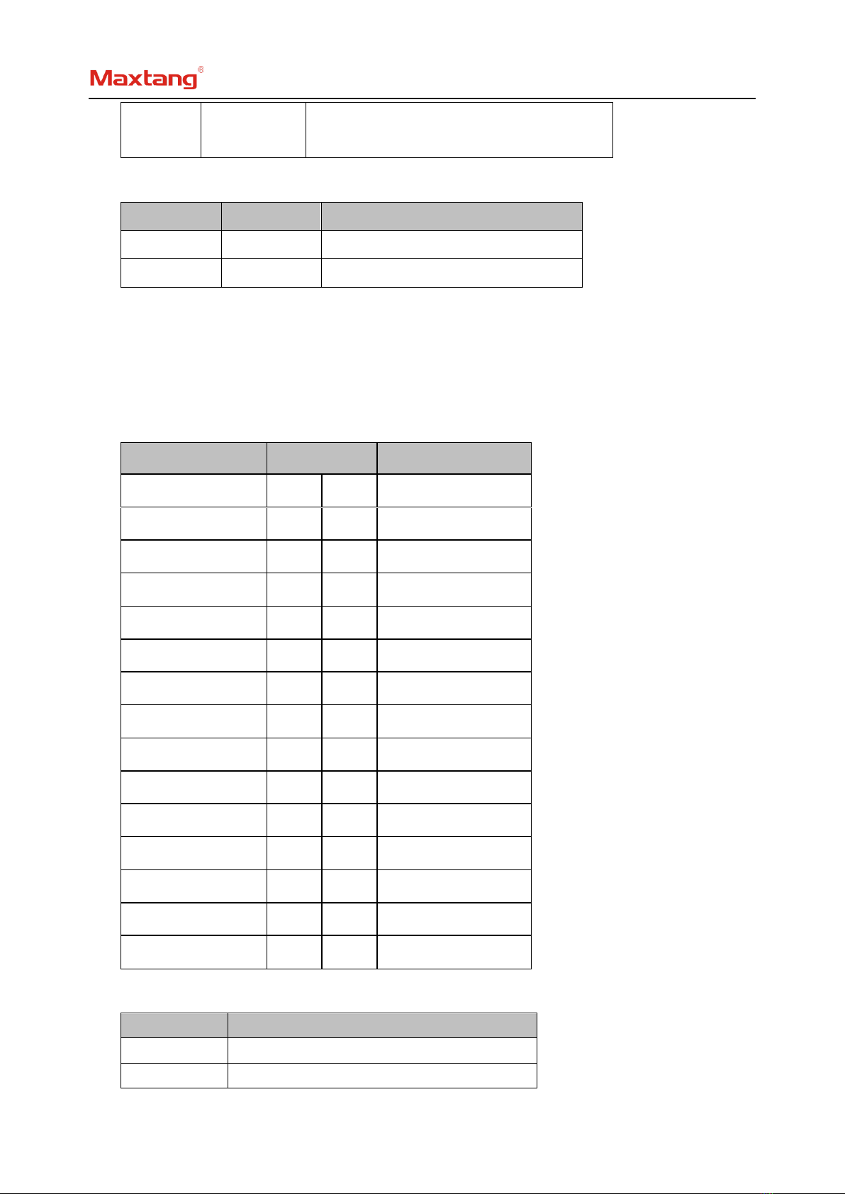
2.2 Jumper Setting
Please configure the jumpers according to your requirements before installing the hardware.
How to identify the first header of jumpers and pins: Observe the mark beside the jumper or pins and
find the header marked by “1” or bold line or triangular symbol. Or observe the rear panel and the header
with a square solder pad is the first header.
2.3 Memory Slots
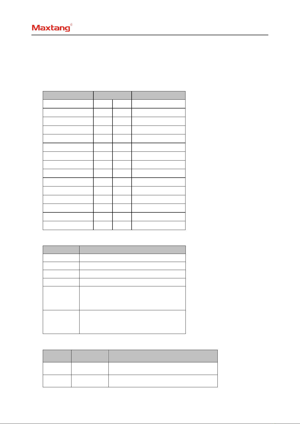
The board provides 2 x SO-DIMM DDR4-3200, supports dual-channel, maximum capacity: 64GB.
Attention: Make sure to hold the memory module and align the key to the module with that on the
memory slot. While choosing a memory module, please make sure the module matches the specification.
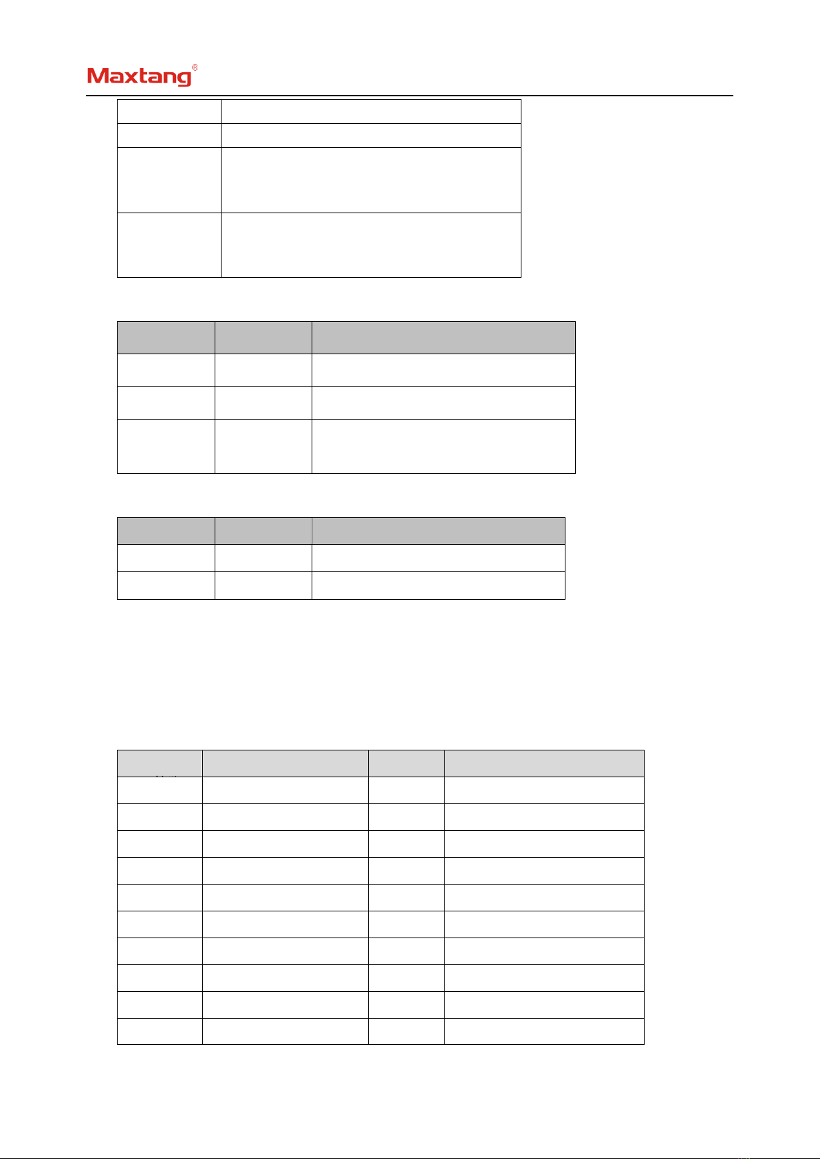
2.4 Display Interfaces
Integrated Intel UHD graphics. Display via 4xHDMI2.0b (supports HDCP2.3), 1x eDP (4Lane 40pin), 1x