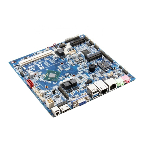
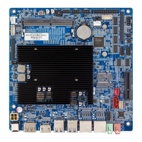
Maxtang BYT-35 User manual

BYT-35 Disk Size SBC Motherboard

Copyright
© 2021 Shenzhen Maxtang Computer Co., Ltd. All rights reserved. No part of this publication may be reproduced,
copied, stored in a retrieval system, translated into any language, or transmitted in any form or by any means,
electronic, mechanical, photocopying, or otherwise, without the prior written consent of Shenzhen Maxtang
Computer Co., Ltd (hereinafter referred to as “Maxtang”).
Disclaimer
Maxtang reserves the right to make changes and improvements to the products described in this document without
prior notice. Every effort has been made to ensure the information in the document is correct; however, Maxtang
does not guarantee this document is error-free.
Maxtang assumes no liability for incidental or consequential damages arising from misapplication or inability to use
the product or the information contained herein, nor for any infringements of rights of third parties, which may result
from its use.
Trademarks
All the trademarks, registrations, and brands mentioned herein are used for identification purposes only and may be
trademarks and/or registered trademarks of their respective owners.

Shenzhen Maxtang Computer Co., Ltd
1
BYT35 Motherboard
User Manual
(Version 1.5)
Version:
NO.
Description
Issue Date:
V1.0
Initial Version
2018/04/27
V1.5
Updated the power to 12V/19V DC-in
2021/10/28

Shenzhen Maxtang Computer Co., Ltd
2
Contents
Chapter 1 Product Introduction ......................................................................................................3
1.1 Brief Introduction ..................................................................................................................3
1.2 Parameters.............................................................................................................................3
Chapter 2 Hardware............................................................................4
2.1 Connector Diagram................................................................................................................4
2.2 Jumper Setting.......................................................................................................................5
2.3 Memory Slots.........................................................................................................................5
2.4 Display Interfaces...................................................................................................................5
2.5 Storage (Screen Printing: MSATA, SATA1, PWSATA).............................................................7
2.6 USB Interface .........................................................................................................................7
2.6 LAN.........................................................................................................................................8
2.8 Audio Interface ......................................................................................................................8
2.9 COM .......................................................................................................................................8
2.10 GPIO (Screen Printing: GPIO) ...............................................................................................9
2.11 LPC (optional).......................................................................................................................9
2.13 Switch Button/ Indicator Pin (Screen Printing: JPOWER) ..................................................10
2.14 Hardware Auto Start (Screen Printing: JAT).......................................................................10
2.15 CMOS Clearance/Retention (Screen Printing: JCMOS)......................................................10

Shenzhen Maxtang Computer Co., Ltd
3
Chapter 1 Product Introduction
1.1 Brief Introduction
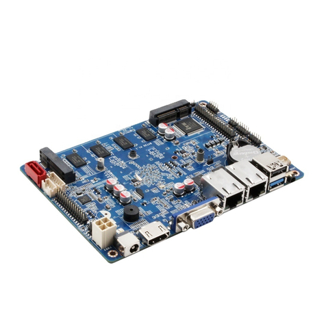
The BYT-35 V1.5 motherboard is a 3.5" SBC (Single Board Computer) based on the Intel Bay Trail platform,
features small form factor, low power consumption and high performance.
1.2 Parameters
Bay Trail Platform:
⚫Celeron J1900, quad-core, 1.8GHz - 2.42GHz, TDP 10W, supports EIST
⚫Celeron J1800, dual-core, 2.41GHz - 2.58GHz, TDP 10W, supports EIST
⚫Celeron N2940, quad-core, 1.83GHz - 2.25GHz, TDP 7.5W, supports EIST
⚫Celeron N2807, dual-core, 1.58GHz – 2.16GHz, supports EIST
Memory:
⚫CPU J1900/1800/N2940----on-board DDR3L-1333, supports dual channel, maximum capacity
4GB(2x2GB)
⚫CPU N2807----on-board DDR3L-1333, single channel, maximum capacity 2GB
GPU: Integrated Graphics based on CPU, Display via 1x HDMI1.4, 1xVGA,1x LVDs (eDP optional), supports dual
independent displays.
Storage: 1 x mSATA (Compliant with SATA2.0), 1 x standard SATA2.0, eMMC optional
USB: 1x USB3.0 Gen 1, 5x USB2.0
Ethernet: 2x Gigabyte Network Controllers (Intel)
Audio: High-Definition Audio Codecs, supports Speaker-out, Mic-in, and power amplifier functions
Other I/O: 1x mini-PCIe, Micro SIM, support WIFI/BT/3G/4G module; a set of LPC(optional), a set of GPIO, 4xRS232,
2xRS485
Dimension: 146mm x 102mm (3.5")
Power: 12V/19V DC-in (12V~36V optional)
Working Temperature: -20℃~60℃

Shenzhen Maxtang Computer Co., Ltd
4
Chapter 2 Hardware
2.1 Connector Diagram

Shenzhen Maxtang Computer Co., Ltd
5
2.2 Jumper Setting
Please configure the jumpers according to your requirements before installing the hardware.
How to identify the first header of jumpers and pins: Observe the mark beside the jumper or pins and find the
header marked by “1” or bold line or triangular symbol. Or observe the rear panel and the header with a
square solder pad is the first header.
2.3 Memory Slots
Onboard memory design and the memory configurations vary on different CPUs.
CPU
Memory Type
Capacity
Channel
J1900
DDR3L 1333
4GB
Dual channel
J1800
DDR3L 1333
4GB
Dual channel
N2940
DDR3L 1333
4GB
Dual channel
N2807
DDR3L 1333
2GB
Single channel
2.4 Display Interfaces
The board features Integrated graphics, supports 1xHDMI, 1xVGA, 1x 24bit Dual Channel LVDs. Supports dual
independent display.
The LVDs can be set as 2 lanes eDP, when it is configured as eDP function the LVDs function will be disabled.
The onboard VGA interface is reserved as an alternative option, the onboard VGA interface cannot be used at
the same time as the rear standard VGA interface.
2.4.1 LVDS (Screen printing: EDP/LVDS, EDP/LVDS_ADJ, J3)
When it is configured as LVDS function, the "EDP/LVDS" pin transmits LVDS signals, the " EDP/LVDS_ADJ," pin
is the backlight adjustment jumper, and the operating voltage of the screen is controlled by the "J3" pin.
LVDS Data Pin (EDP/LVDS):
Signal
Pin
Signal
VCC
1
2
VCC
VCC
3
4
GND
GND
5
6
GND
A_DATA0_DN
7
8
A_DATA0_DP
A_DATA1_DN
9
10
A_DATA1_DP
A_DATA2_DN
11
12
A_DATA2_DP
GND
13
14
GND
A_CLK_DN
15
16
A_CLK_DP
A_DATA3_DN
17
18
A_DATA3_DP
B_DATA0_DN
19
20
B_DATA0_DP
B_DATA1_DN
21
22
B_DATA1_DP
B_DATA2_DN
23
24
B_DATA2_DP
GND
25
26
GND
B_CLK_DN
27
28
B_CLK_DP
B_DATA3_DN
29
30
B_DATA3_DP

Shenzhen Maxtang Computer Co., Ltd
6
LVDS Backlight Pin (eDP/LVDS_ADJ):
Pin
Signal
1
GND
2
GND
3
LCD_BKL_ADJ
4
LCD_BKL_ON
5
12V
6
12V
LVDS Operating Voltage Pin (J3):
Interface
Setting
Function
1-2
Close
VCC(+3.3V)
3-4
Close
VCC(+5V)
5-6
Close
VCC(+12V)
Note: LVDS screen’s power can be adjusted among 12V/5V/3.3V via jumper setting. Customers can connect
voltage with jumper cap according to their LVDS screen’s voltage (Connecting different voltages via jumper
cap at the same time is strictly forbidden).
2.4.2 eDP (Optional)
When it is set as eDP functions, the “EDP/LVDS” pin transmits the eDP signal, the " EDP/LVDS_ADJ," pin is the
backlight adjustment jumper, and the operating voltage of the screen is controlled by the "J3" pin.
eDP Data Pin (Screen Printing: EDP/LVDS)
Signal
Pin
Signal
VCC
1
2
VCC
VCC
3
4
EDP_HPD
GND
5
6
GND
EDP_AUXN
7
8
EDP_AUXP
N/A
9
10
N/A
EDP_DATA0_P
11
12
EDP_DATA0_N
GND
13
14
GND
N/A
15
16
N/A
EDP_DATA1_P
17
18
EDP_DATA1_N
N/A
19
20
N/A
N/A
21
22
N/A
N/A
23
24
N/A
GND
25
26
GND
N/A
27
28
N/A
N/A
29
30
N/A
eDP Backlight Pin (Screen Printing: eDP/LVDS_ADJ)
Pin
Signal
1
GND
2
GND

Shenzhen Maxtang Computer Co., Ltd
7
3
LCD_BKL_ADJ
4
LCD_BKL_ON
5
12V
6
12V
EDP Operating Voltage Pin (Screen Printing: J3)
Interface
Setting
Function
1-2
Close
VCC(+3.3V)
3-4
Close
VCC(+5V)
5-6
Close
VCC(+12V)
Note: The eDP screen’s power can be flexibly adjusted between 12V/5V/3.3V via jumper setting. It is strictly
forbidden to short-circuit pins of different voltages at the same time.
2.4.3 VGA Backup interface (Screen Printing: JVGA)
Signal
Pin
Signal
VGA_R
1
2
GND
VGA_G
3
4
GND
VGA_B
5
6
GND
V_SYNC
7
8
DDC_DAT
H_SYNC
9
10
DDC_CLK
2.5 Storage (Screen Printing: MSATA, SATA1, PWSATA)
The board supports 1x mSATA interface (Standard SATA2.0) and 1x Standard SATA2.0 interface.
Onboard eMMC optional, capacity can be chosen from 8GB/32GB/64GB.
The “PWSATA” is the power supply of the SATA disk, only applies to a 2.5” hard disk.
Hard Disk Power Supply (Screen Printing: PWSATA)
Pin
Signal
1
5V
2
GND
3
GND
4
5V
2.6 USB Interface
The board supports 1x USB3. 0 and 5x USB2.0(4*header on board, 2.0mm spacing)
Internal USB2.0 Pin (Screen Printing: USB20, USB21)
Signal
Pin
Signal
VCC 5V
1
2
VCC 5V
USB DATA-
3
4
USB DATA-
USB DATA+
5
6
USB DATA+
GND
7
8
GND
(NUL)
9
10
(NC)

Shenzhen Maxtang Computer Co., Ltd
8
2.6 LAN
The board is equipped with two Intel i211 Gigabit Network Controller, RJ45 interface, supports Magic
packet wake-up and PXE network boot.
LED Status Indicators:
LI_LED Status (Orange)
Function
ACT_LED Status (Green)
Function
Always on
Network Connected
Blinking
Data transfer
2.8 Audio Interface
The board features Realtek HD audio codec ALC662 supports a 3.5mm Line-out/MIC two-in-one combo
jack (CTIA American standard), and a built-in dual-channel power amplifier output socket for connecting
passive speakers.
Two-in-one headphone jack:
JAUD (Screen Printing: JAUD)
Pin
Signal
1
L+
2
L-
3
R-
4
R+
2.9 COM
The board provides 4x RS232 and 2xRS485 onboard serial port headers (2.0mm spacing). the RS232
serial port headers are electrified, the voltages are the same as the input voltage of the board.
RS232 COM (Screen Printing:COM14)
Signal
Pin
Signal
DCD#
1
2
RXD
TXD
3
4
DTR#
GND
5
6
DSR#
RTS#
7
8
CTS#
RI#
9
10
VCC(same as board input)
)
DCD#
11
12
RXD
TXD
13
14
DTR#
GND
15
16
DSR#
RTS#
17
18
CTS#
RI#
19
20
VCC(same as board input)
)
DCD#
21
22
RXD
TXD
23
24
DTR#

Shenzhen Maxtang Computer Co., Ltd
9
GND
25
26
DSR#
RTS#
27
28
CTS#
RI#
29
30
VCC(same as board input)
)
DCD#
31
32
RXD
TXD
33
34
DTR#
GND
35
36
DSR#
RTS#
37
38
CTS#
RI#
39
40
VCC(same as board input)
)
RS485 (Screen: COM5_6)
Signal
Pin
Signal
COM5_DATA-
1
2
COM6_DATA-
COM5_DATA+
3
4
COM6_DATA+
GND
5
6
GND
2.10 GPIO (Screen Printing: GPIO)
The board provides a set of 2x5Pin GPIO (2.0mm spacing), 8 lanes of programmable I/O in total.
GPIO (Screen Printing:GPIO)
Signal
Pin
Pin
Signal
SIO_GP70
1
2
3.3V
SIO_GP71
3
4
SIO_GP74
SIO_GP72
5
6
SIO_GP75
SIO_GP73
7
8
SIO_GP76
GND
9
10
SIO_GP77
2.11 LPC (optional)
The board provides 1 x LPC (Low Pin Count Interface, 2.0 mm spacing) to connect peripheral LPC
equipment, optional.
LPC:
Signal
Pin
Signal
L_FRAME_N
1
2
LPC_AD3
LPC_AD2
3
4
LPC_AD1
LPC_AD0
5
6
GND
PLTRST
7
8
CLK_LPC
3.3V
9
10
SERIRQ
2.12 Board Power Supply (Screen Printing: DCIN, PWR2)
The board supports a 12V/19V DC-in power supply.
DCIN:

Shenzhen Maxtang Computer Co., Ltd
10
PWR2 (Screen Printing:PWR2)
Definition
Pin
Definition
GND
2
1
GND
VIN
3
4
VIN
2.13 Switch Button/ Indicator Pin (Screen Printing: JPOWER)
The board has a set of 2.0mm spacing pins that can be connected to a switch button, a system reset
button, a hard disk read/write indicator, a power-on indicator.
JPOWER:
Signal
Pin
Signal
HDD_LED+
1
2
PWR_LED+
HDD_LED-
3
4
PWR_LED-
RSTBTN+
5
6
PWR_ON+
RSTBTN-
7
8
PWR_ON-
(NC)
9
10
(NUL)
2.14 Hardware Auto Start (Screen Printing: JAT)
JAT (Screen Printing: JAT)
Setting
JAT
Close
Hardware Auto Start
Please note that this jumper’s function is similar to the BIOS’s “Restore AC Power Loss” function. When
the latter is set to power on, the device will also start automatically after power is connected
2.15 CMOS Clearance/Retention (Screen Printing: JCMOS)
CMOS is powered by onboard button batteries. Clearing CMOS will permanently remove the previous
system settings and restore the board system to original settings (factory settings).
Step 1: Turn off the PC and disconnect the power adapter.
Step 2: Connect the 1st and 2nd pin of JCMOS for 10 seconds through the jumper cap then
disconnect.
Step 3: Restart the device, press the <DEL> button to enter the BIOS, load the optimal default value,
save, and exit the settings.
CLR_CMOS:
Setting
JCMOS
Close
Clear CMOS
Please do not clear COMS when the PC is connected to power in case board damages.
Table of contents
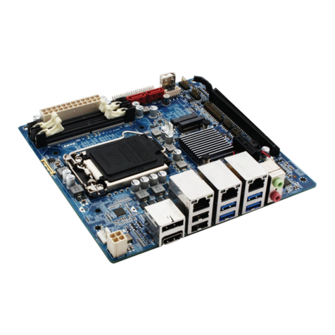
Other Maxtang Motherboard manuals

Maxtang
Maxtang WL10 User manual

Maxtang
Maxtang BW-35 User manual

Maxtang
Maxtang BYT60 User manual

Maxtang
Maxtang FP-10 User manual

Maxtang
Maxtang DTJ6412-I User manual
Maxtang
Maxtang WL10 User manual

Maxtang
Maxtang SKD70 User manual
Maxtang
Maxtang ALN50 User manual

Maxtang
Maxtang MITX-BYT70 User manual

Maxtang
Maxtang SKD70 User manual

Maxtang
Maxtang FP20 User manual

Maxtang
Maxtang WL35 User manual

Maxtang
Maxtang APL-35 User manual

Maxtang
Maxtang TL10 User manual
Maxtang
Maxtang AL-10 User manual

Maxtang
Maxtang WL35 User manual
Maxtang
Maxtang KL35 User manual

Maxtang
Maxtang DTJ6412-A User manual

Maxtang
Maxtang JSL-15 User manual

Maxtang
Maxtang EHL-10 User manual