Maxtang WL35 User manual

Shenzhen Maxtang Computer Co., Ltd
1
WL35 Motherboard
User Manual
(Version 1.0)
Version:
NO.
Description
Issue Date:
V1.0
Initial version
2021/4/9

Shenzhen Maxtang Computer Co., Ltd
2
Contents
Chapter 1 Product Introduction................................................................................ 3
1.1 Brief Introduction....................................................................................................................................... 3
1.2 Parameters.................................................................................................................................................. 3
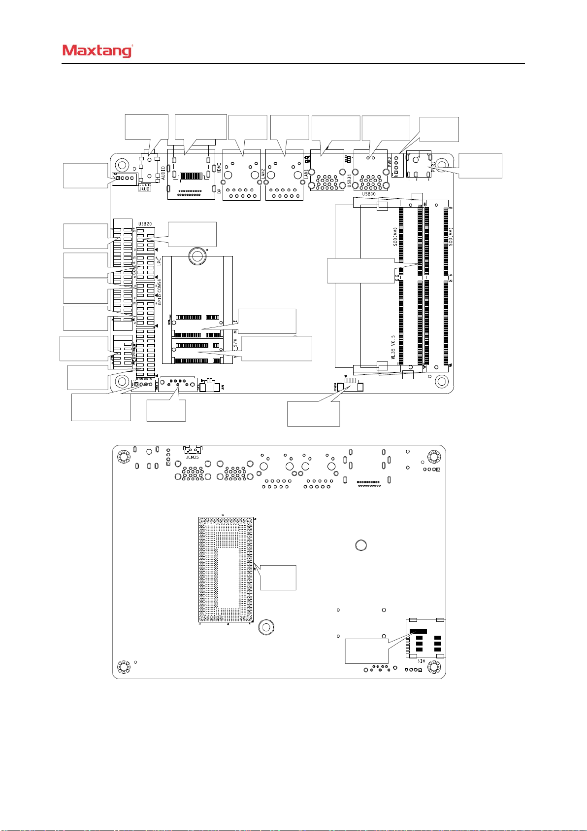
1.3 Connector Diagram .................................................................................................................................... 4
Chapter 2 Hardware ................................................................................................. 5
2.1 Jumper Setting............................................................................................................................................ 5
2.2 Memory Slots............................................................................................................................................. 5
2.3 Display Interfaces....................................................................................................................................... 5
2.4 Expansion(screen printing:M.2_E) ............................................................................................................ 5
2.5 Storage(screen printing:M.2_S/W、SATA、PWSATA) ........................................................................... 5
2.6 USB Interface............................................................................................................................................. 6
2.7 LAN ........................................................................................................................................................... 6
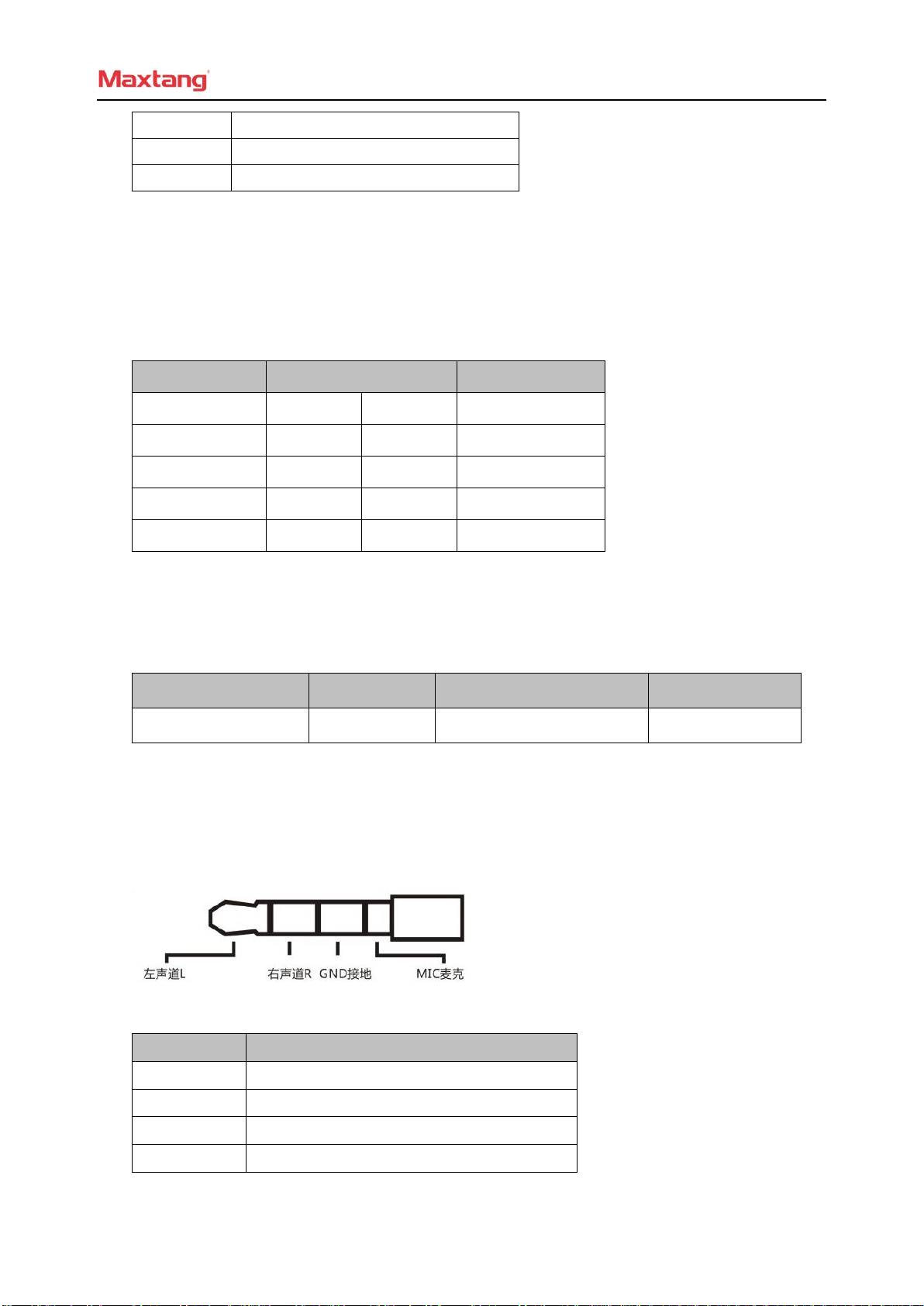
2.8 Audio Interface........................................................................................................................................... 6
2.9 COM .......................................................................................................................................................... 7
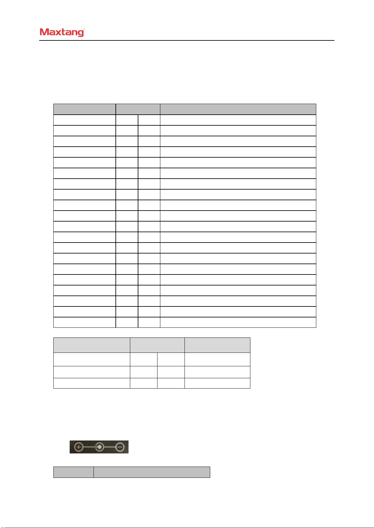
2.10 Power Supply(screen printing:PWR1、PWR2)....................................................................................... 7
2.11 GPIO(screen printing:GPIO).................................................................................................................... 8
2.12 LPC(Optional).......................................................................................................................................... 8
2.13 Switch button/indicator pin(screen printing:JPOWER) ........................................................................... 8
2.14 CPU FAN Socket(screen printing:CPU_FAN)......................................................................................... 9
2.15 CMOS Clearance/Retention(screen printing:JCMOS).......................................................................... 9

Shenzhen Maxtang Computer Co., Ltd
3
Chapter 1 Product Introduction
1.1 Brief Introduction
The WL35 motherboard is a 3.5" SBC (Single Board Computer) based on the Intel Whiskey Lake-U platform,
small formed with low power consumption and high performance.
1.2 Parameters
CPU:
i7-8565U — Quad Core Eight Threads, Base Frequency 1.8GHz, Turbo Frequency 4.6GHz,TDP 15W
i5-8365U — Dual Core Eight Threads, Base Frequency 1.6GHz, Turbo Frequency 3.9GHz,TDP 15W
i3-8145U — Dual Core Four Threads, Base Frequency 2.1GHz, Turbo Frequency 3.9GHz,TDP 15W
Celeron 4205U — Dual-Core Two Threads, Base Frequency 1.8GHz, TDP 15W
Memory: Dual Channel SO-DIMM DDR4, Up to 64GB
GPU: Integrated Graphics based on CPU,Display via 1x HDMI,1x DP,1x eDP.
Storage:1 x M.2 Key B for 2242 SSD (SATA Definition) /4G Module, 1x SATA3.0
USB: 4xUSB3.1 Gen2,2xUSB2.0
Ethernet:2xGigabyte Network Card(1x Intel i211, 1x Intel i219)
Audio: High-definition audio chip, supports Speaker-out, Mic-in, and power amplifier
Other I/O:1xM.2 Key E(Type 2230,for Wi-Fi card and Bluetooth),1xLPC(set), 1xGPIO(set), 4xRS232,
2xRS485
Dimension:146mm x 102mm (3.5")
Power:12V DC-in
Working Temperature:-20℃~60℃

Shenzhen Maxtang Computer Co., Ltd
4
1.3 Connector Diagram
DC_IN
PWR2
USB3.0
USB3.0
LAN1
LAN2
HDMI+DP
AUDIO
JAUD
COM14
JPOWER
EDP
GPIO
COM56
LPC
USB2.0
M.2_WIFI
M.2_SSD/4G
PWSATA
SATA
CPU_FAN
SO-DIMM
CPU
SIM

Shenzhen Maxtang Computer Co., Ltd
5
Chapter 2 Hardware
2.1 Jumper Setting
Please configure the jumpers according to your requirements before installing the hardware.
How to identify the first header of jumpers and pins: Observe the mark beside the jumper or pins and find
the header marked by “1” or bold line or triangular symbol. Or observe the rear panel and the header with a
square solder pad is the first header.
2.2 Memory Slots
On-board 2 x SO-DIMM DDR4 slots, supporting dual channels, maximum capacity 64 GB.
2.3 Display Interfaces
1x HDMI (1.4) standard interface.
1x DP (1.2) interface.
1x eDP (1.3) interface, the screen power supply LCD_VCC defaults to 3.3V, and BL_PWR defaults to
12V (Note: the backlight output voltage is the same as the power input voltage)。
eDP: (screen printing: EDP)
Signal
Pin
Pin
Pin
Pin
Signal
GND
1
2
GND
LINE1_N
3
4
LINE1_P
LINE0_N
5
6
LINE_P
AUX_N
7
8
AUX_P
GND
9
10
GND
SMB_CLK
11
12
SMB_DAT
HPD
13
14
LCD_VCC
BL_EN
15
16
BL_PWM
GND
17
18
GND
BL_PWR
19
20
BL_PWR
2.4 Expansion (screen printing: M.2_E)
Screen printing M.2_E: M.2 slots Key E,Supports 2230 WIFI Card with Bluetooth functions.
2.5 Storage (screen printing: M.2_S/W、SATA、PWSATA)
Screen printing M.2_S/W: M.2 slot Key B, supports 2242 SATA protocol SSD/4G module, and has a
Micro SIM card slot; supports 1xSATA3.0, provides 1xPWSATA hard disk power supply socket (only supports
2.5-inch disks).
PWSATA:(screen printing:PWSATA)
Pin
Signal
1
5V

Shenzhen Maxtang Computer Co., Ltd
6
2
GND
3
GND
4
NC
2.6 USB Interface
4 standard USB3.1 Gen2, 2 built-in USB2.0 interfaces (2.0mm pitch pins).
The rear USB3.1 Gen2 port is powered by 5V Standby voltage, which can supply power to external
devices when it is turned off (not power-off): 5V/1A.
Internal USB2.0 Pin(screen printing: USB2.0):
Signal
Pin
Signal
VCC 5V
1
2
VCC 5V
USB DATA-
3
4
USB DATA-
USB DATA+
5
6
USB DATA+
GND
7
8
GND
NC
9
10
(空)
2.7 LAN
The board provides two high-performance RJ45 interfaces, installed Intel Gigabit Ethernet control chips
i219 (LAN1) and i211 (LAN2), supports Magic packet wake-up.
Interface LED Status Indicators:
LI_LED(Green)Status
Function
ACT_LED(Orange)Status
Function
Always on
Network Connected
Blink
Data transfer
2.8 Audio Interface
The board equips a Realtek HD audio control chip, provides a 3.5mm Line_out/MIC combo jack (CTIA
American standard), and a built-in dual-channel power amplifier output socket for connecting passive
speakers.
Two-in-one headphone jack:
JAUD (screen printing:JAUD):
Pin
Signal
1
L+
2
L-
3
R-
4
R+

Shenzhen Maxtang Computer Co., Ltd
7
2.9 COM
COM header (2.0mm spacing of built-in pins), provides 4x RS232, 2xRS485. The RS232 serial port is
electrified. (Voltage is the same as the input voltage of the board)
RS232(screen printing:COM14):
Signal
Pin
Signal
DCD#
1
2
RXD
TXD
3
4
DTR#
GND
5
6
DSR#
RTS#
7
8
CTS#
RI#
9
10
VCC(same as the input voltage of the board)
DCD#
11
12
RXD
TXD
13
14
DTR#
GND
15
16
DSR#
RTS#
17
18
CTS#
RI#
19
20
VCC(same as the input voltage of the board)
DCD#
21
22
RXD
TXD
23
24
DTR#
GND
25
26
DSR#
RTS#
27
28
CTS#
RI#
29
30
VCC(same as the input voltage of the board)
DCD#
31
32
RXD
TXD
33
34
DTR#
GND
35
36
DSR#
RTS#
37
38
CTS#
RI#
39
40
VCC(same as the input voltage of the board)
RS485(screen printing: COM5_6):
Signal
Pin
Signal
COM5_DATA-
1
2
COM6_DATA-
COM5_DATA+
3
4
COM6_DATA+
GND
5
6
GND
2.10 Power Supply (screen printing: PWR1、PWR2)
Support 12V DC-in for power supply.
PWR1:
PWR2:(screen printing: PWR2)
Pin
Signal

Shenzhen Maxtang Computer Co., Ltd
8
1
VIN
2
VIN
3
GND
4
GND
2.11 GPIO (screen printing: GPIO)
The board is equipped with a set of 2 x 5pin as JGPIO pin (2.0mm spacing), supporting 8 programmable
I/O lanes in total.
GPIO:(screen printing: GPIO)
Signal
Pin
Signal
SIO_GP70
1
2
3.3V
SIO_GP71
3
4
SIO_GP74
SIO_GP72
5
6
SIO_GP75
SIO_GP73
7
8
SIO_GP76
GND
9
10
SIO_GP77
2.12 LPC (Optional)
The board provides a set of 2.0mm pitch LPC (Low Pin Count Interface) pins for connecting external
LPC devices. This is an optional feature.
LPC:(screen printing: LPC)
Signal
Pin
Signal
L_FRAME_N
1
2
LPC_AD3
LPC_AD2
3
4
LPC_AD1
LPC_AD0
5
6
GND
PLTRST
7
8
CLK_LPC
3.3V
9
10
SERIRQ
2.13 Switch button/indicator pin (screen printing: JPOWER)
A set of 2.0mm pitch pins can be connected to 1 switch button, 1 system reset button, 1 hard disk
read/write indicator and 1 power-on indicator.
In addition, a hard disk read/write indicator (red) and a power-on indicator (blue) are designed on the rear
IO panel port on the board.
JPOWER:(screen printing:JPOWER)
Signal
Pin
Signal
HDD_LED+
1
2
PWR_LED+

Shenzhen Maxtang Computer Co., Ltd
9
HDD_LED-
3
4
PWR_LED-
RSTBTN-
5
6
PWR_ON+
RSTBTN+
7
8
PWR_ON-
NC
9
10
2.14 CPU FAN Socket (screen printing: CPU_FAN)
The board provides a CPU cooling fan socket, which offers better heat dissipation when necessary.
CPU_FAN:
Pin
Signal
1
VCC(default 5V power supply (12V Optional)
2
GND
3
CPUFAN_TAC
4
CPUFAN_CTL
2.15 CMOS Clearance/Retention(screen printing: JCMOS)
CMOS is powered by onboard button batteries. Clearing CMOS will permanently remove the previous
system settings and restore the board to the original (factory settings) system settings.
Step 1: Turn off the PC and disconnect the power adapter.
Step 2: Press JCMOS for about 10 seconds and disconnect.
Step 3: When starting the device, press the <DEL> button to enter the BIOS, load the optimal default
value and save and exit the settings.
Please do not clear COMS when the PC is connected to power in case board damages.
Other manuals for WL35
1
Table of contents
Other Maxtang Motherboard manuals

Maxtang
Maxtang APL-35 User manual

Maxtang
Maxtang SKD70 User manual

Maxtang
Maxtang EHL-10 User manual

Maxtang
Maxtang MITX-BYT70 User manual

Maxtang
Maxtang JSL-15 User manual

Maxtang
Maxtang SKD70 User manual

Maxtang
Maxtang FP20 User manual

Maxtang
Maxtang AL-10 User manual

Maxtang
Maxtang BYT-35 User manual

Maxtang
Maxtang BYT60 User manual

Maxtang
Maxtang MITX-KL10 User manual

Maxtang
Maxtang WL10 User manual

Maxtang
Maxtang KL35 User manual

Maxtang
Maxtang BW-35 User manual

Maxtang
Maxtang DTJ6412-I User manual

Maxtang
Maxtang TL10 User manual

Maxtang
Maxtang WL35 User manual

Maxtang
Maxtang EHL-35 User manual

Maxtang
Maxtang WL10 User manual

Maxtang
Maxtang FP-10 User manual