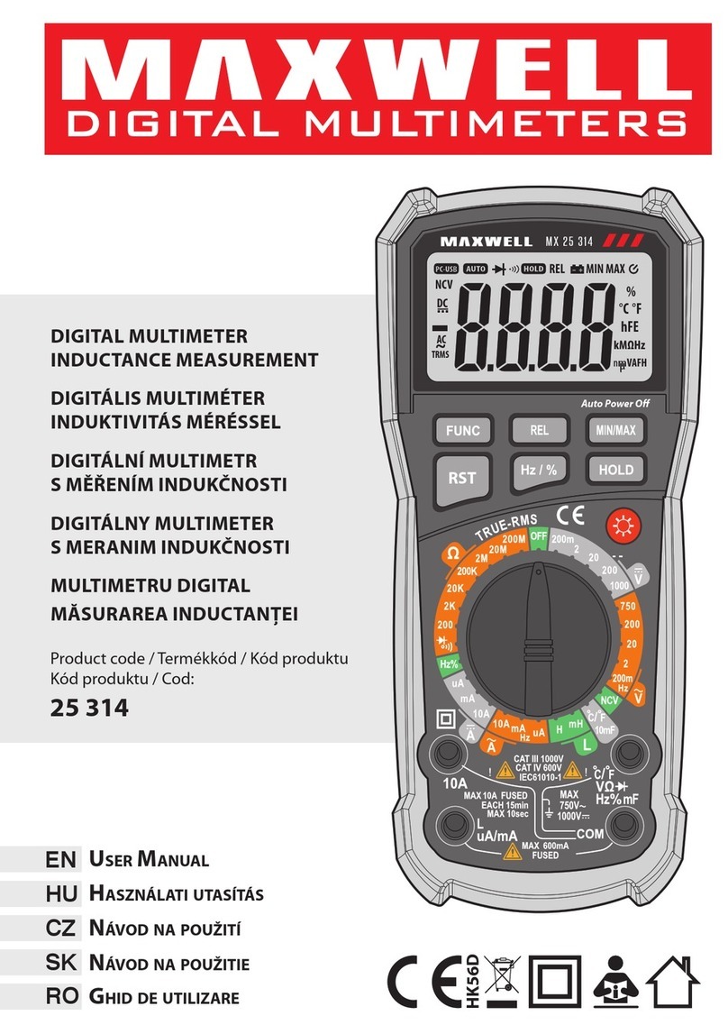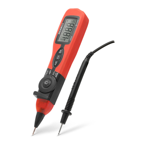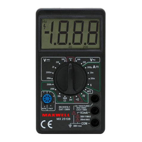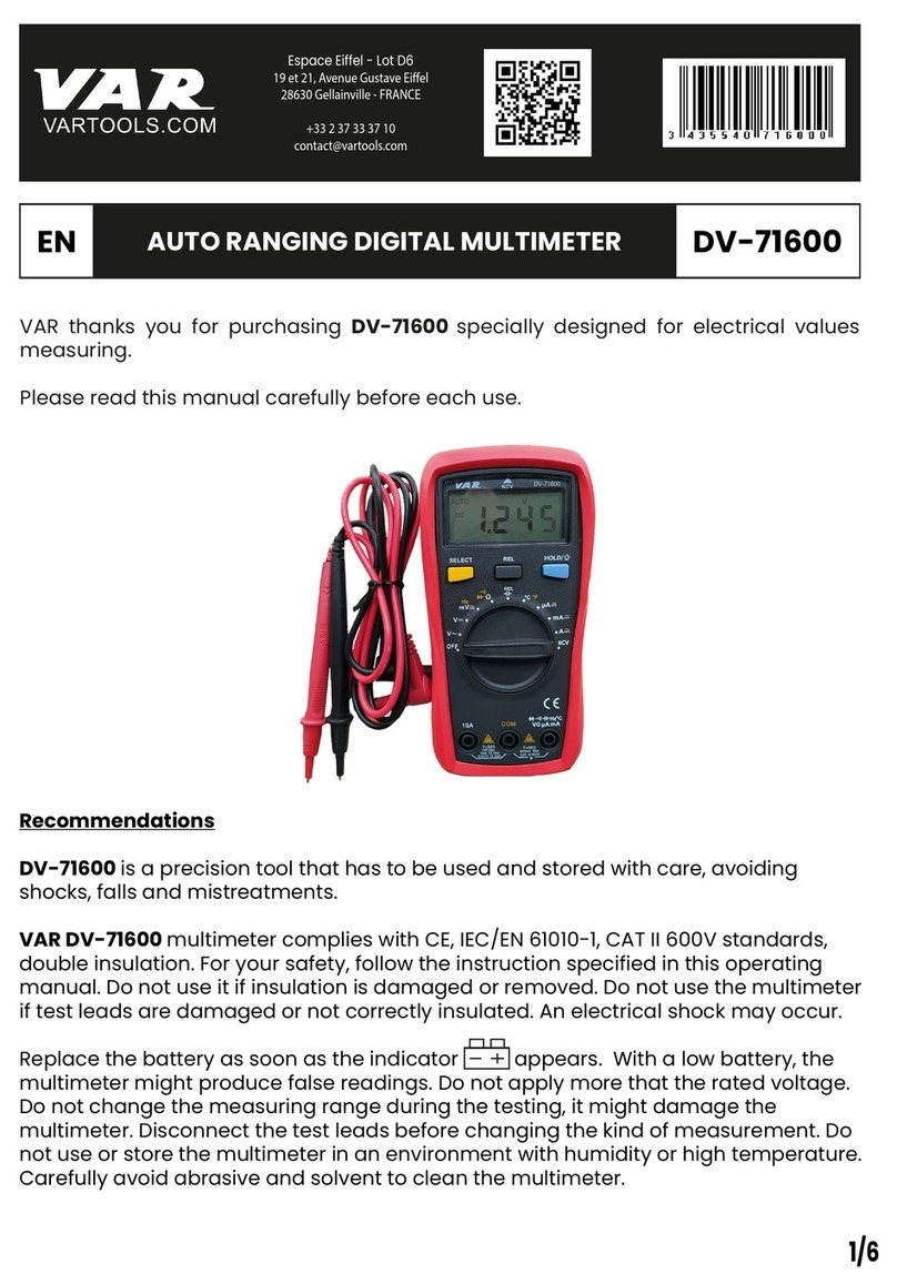
EN User Manual
3. Connect the black test lead to the COM port, and the
red test lead to the port.
4. Touch the red lead to the diode’s anode and the black
lead to its cathode.
5. The opening voltage of the diode will be read on the
display. If the polarity is accidentally reversed, the„OL”
icon will appear on the display.
• ATTENTION: In order to avoid damage to the device
or electric shock, cut o the external power source of
the circuit to be measured, or turn o the high - power
capacitors!
Continuity, discontinuity test
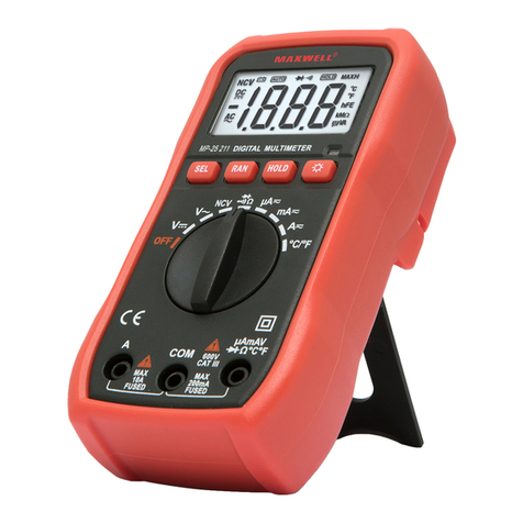
1. Set the function switch to the position.
2. Connect the black test lead to the “COM” port, and the
red test lead to the port.
3. Connect the other ends of the test leads to the circuit
under test. If the resistance between the two points is less
than 70 Ω, the device indicates this with a beeping sound.
• Note: the continuity test is also good for looking at the
open/closed state of a circuit.
• ATTENTION: In order to avoid damage to the device or
electric shock, cut o the external power source of the circuit
to be measured, or turn o the high-power capacitors!
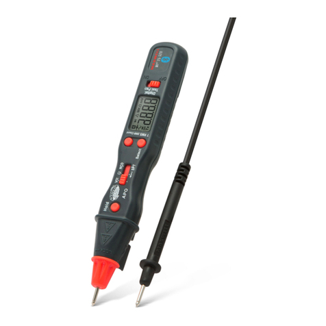
NCV (Non-Contact-Voltage) – Detection
1. Set the function selector to theLive
NCV position.
2. Press the SEL button to select the NCV (EF display)
function.
3. Bring the top of the instrument (the part above the
display) close to the wire to be tested. When voltage
is present, the instrument indicates it by intermittent
beeping and ashing of the LED.
LIVE - Phase detection function
• Set the function selector toLive
NCV. Press the SEL button
to select the LIVE function.
• Connect the red test lead to the socket and
touch the test tip to the uninsulated end of the wire to be
tested. When a phase is present, the instrument indicates
it with an intermittent beep and ashing of the LED.
• ATTENTION: the indication of the non-contact
detector does not always give an accurate value, since
the sensitivity of the instrument always depends on the
thickness of the insulation. This mode is only suitable
for sensing AC voltage.
Frequency
• Set the function switch to HZ/%.
• Press the SEL button to select the HZ function.
• Connect the test leads to the COM and sockets.
• Connect the instrument leads to the signal source to
be measured.
Note:
• Do not measure frequency at a voltage higher than
250 V(RMS).
• In noisy environments, it is advisable to use a shielded
cable when measuring small signals.
• Avoid touching the circuit when measuring at high voltage.
Capacity measurement
1. Set the function switch to capacity mode.
2. Briey press the SEL button until Fappears on the
display.
3. Connect the test leads to the socket and connect the
black to the COM socket.
4. Connect the probes to the capacitor to be measured. In
the case of a polarized capacitor, pay attention to the
correct polarity.
• Before measuring capacity, fry the capacitor to
be measured. Measuring mF capacitors can take
several seconds.
Duty cycle measurement %
• Set the function switch to HZ/%.
• Press the SEL button to select the %function.
• Connect the instrument cable to the COM and
sockets and then to the signal source to be measured.
MIN/MAX/REL measurement
• Press briey to store and display the minimum or
maximum measurement value.
• A long press exits the function, and a repeated
long press switches the instrument to relative
measurement mode.
Maintenance, cleaning
• This is a factory-calibrated, accurate meter. Do not disassemble
the device or attempt to modify the electrical circuit. Make sure
the measuring instrument is water-, dust-, and shatter-proof.
• Please do not store or use in high temperature, high humidity,
re or strong magnetic environment.
• Please wipe the meter with a damp cloth and mild detergent,
and do not use abrasive and drastic solvents such as alcohol.
• If you do not use it for a long time, please remove the battery
to avoid leakage.
• (Can only be performed by a specialist)
• When replacing the fuse, use another fuse of the same type and
specication.
• (Can only be performed by a specialist)
Troubleshooting
• If the meter does not work properly, check the battery level and
if the problem persists, contact the service center or dealer.
• The manufacturer and distributor assumes no responsibility for
damages resulting from improper, unprofessional use.
Disposal (Electric device)
• Valid in the European Union and all other European states that
participate in selective collection
• According to directives 2012/19/EU, electrical waste and devices
cannot be thrown away as household waste.
• Old appliances must be collected in order to maximize the
recycling of raw materials, thereby reducing their impact on
people’s health and the environment.
• The crossed-out bin symbol is on all products for which
separate collection is mandatory. Consumers should
check with their local authorities for more information.
