EN
User Manual
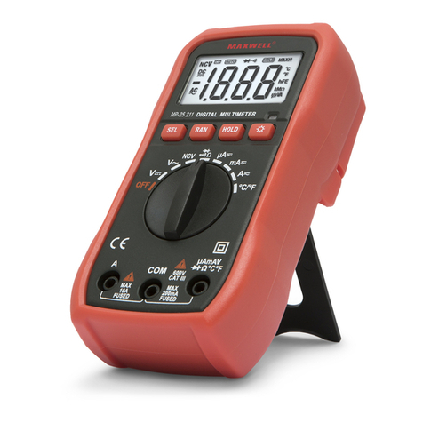
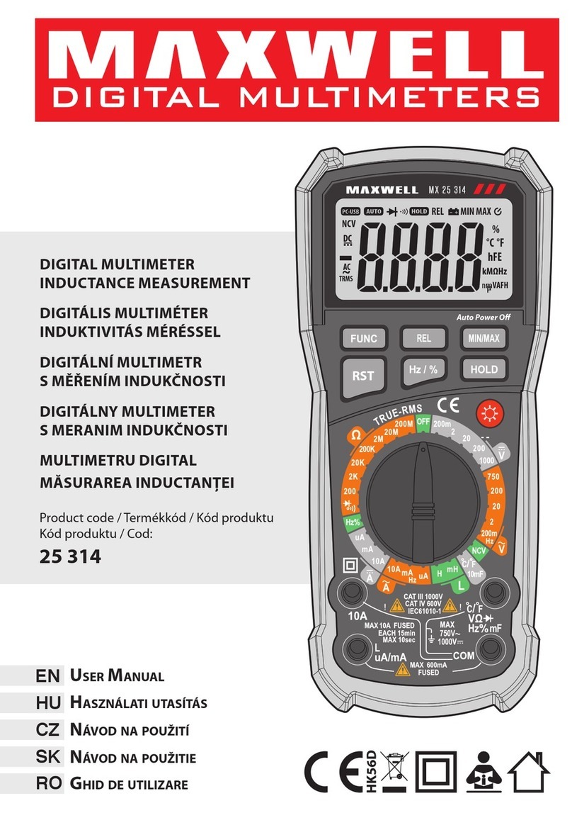
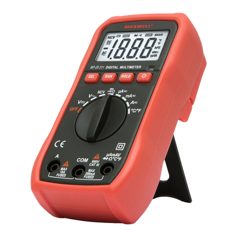
• Backlight on / o. By pressing the button, the backlight
can be switched on and
• It remains on for ~15 seconds, while the measurement
result can be read properly. In order to protect the
battery that ensures the long-term operation of the
device, the backlight turns o automatically.
• ATTENTION: For battery with low energy level, this
function does not work for energy saving reasons.
Button
Worklight on/o. The work light can be switched on and o
by pressing the button.
DC V and AC V measurement
1. Set the function selector switch to
~
mode. By
pressing the SEL button select the voltage type to be
measured (alternating or direct voltage) Connect the
black test lead to the COM port, and the red test lead
to the port.
2. Connect the other end of the test leads to the circuit to
be measured.
3. Read the measured value from the display. The polarity
of the red test lead is shown on the display (only the
negative sign).
• ATTENTION: If you are not sure of the approximate
value of the measured value, set the instrument to the
maximum measurement limit. To avoid electric shock
and damage to the device, never exceed 600 V DC or
600 V AC RMS voltage limit!
DC A and AC A measurement
1. Set the function selector switch to
A~
mode.
2. Select the type of current to be measured (alternating
current or direct current) by pressing the SEL button.
3. Turn o the power supply to the circuit to be measured.
Burn out any high capacity capacitors.
4. Connect the black test lead to the COM port, and the
red test lead to the port for max. 200 mA value,
or connect to the A for max. 10 A value.
5. Connect the multimeter in series with the circuit.
6. Read the measured value from the display. In the case
of DC measurement, the polarity of the red cable is also
shown on the display (only the negative is marked).
• If the display shows OL and the device beeps
continuously, switch to a higher measurement limit.
ATTENTION: If you are not sure of the approximate value
of the measured value, then set the instrument to the
maximum measurement limit. To avoid device failure, check
the condition of the fuse before the measurement! Always
use the specied sizes and values! When measuring current,
do not connect the instrument leads in parallel to the circuit,
as this may cause the circuit and the instrument to fail.
Resistance measurement
1. Set the function switch to the Ωposition.
2. Connect the black test lead to the COM port, and the
red test lead to the port.
3. Before measuring, check that the circuit to be measured
is free of voltage.
4. Connect the test leads to the two ends of the resistor.
5. Read the measured value.
• Note: 20 MΩ within the measuring range, the device
needs a few seconds for a stable measurement.
• If the measured circuit exceeds the maximum
measurement limit, the display shows OL.
• ATTENTION: If you are not sure of the approximate
value of the measured value, set the instrument to
the maximum measurement limit. In order to avoid
damage to the device or electric shock, cut o the
external power source of the circuit to be measured, or
turn o the high-power capacitors!
Diode measurement
1. Set the function switch to the position.
2. Press the SEL button to select the diode test function .
3. Connect the black test lead to the COM port, and the
red test lead to the port.
4. Touch the red lead to the diode’s anode and the black
lead to its cathode.
5. The opening voltage of the diode will be read on the
display. If the polarity is accidentally reversed, the OL
icon will appear on the display.
• ATTENTION: In order to avoid damage to the device
or electric shock, cut o the external power source of
the circuit to be measured, or turn o the high - power
capacitors!
Continuity, discontinuity test
1. Set the function switch to the position.
2. Select the tensile test function by pressing the SEL
key.
3. Connect the black test lead to the COM port, and the
red test lead to the port.
4. Connect the other ends of the test leads to the circuit
under test. If the resistance between the two points is less
than 70 Ω, the device indicates this with a beeping sound.
• Note: the continuity test is also good for looking at the
open/closed state of a circuit.
• ATTENTION: In order to avoid damage to the device
or electric shock, cut o the external power source of
the circuit to be measured, or turn o the high-power
capacitors!
NCV (Non-Contact-Voltage) – Detection
1. Set the function selector to Live
NCV.
2. Press the SEL button to select the NCV function. Bring
the very top of the instrument (the part above the
display) close to the wire to be tested. When voltage
is present, the instrument indicates it by intermittent
beeping and ashing of the LED.
LIVE - Phase detection function
• Set the function selector toLive
NCV . Press the SEL button
to select the LIVE function.
• Connect the red test lead to the socket and
touch the probe to the uninsulated end of the wire
