Installation and Operational Instructions for
EAS®-Compact®overload clutch, Type 49_._ _4._ Sizes 4 and 5 (B.4.14.2.GB)
05/09/2011 TK/GH/SU Chr. Mayr GmbH + Co. KG Tel.: 08341 / 804-0
Eichenstraße 1 Fax: 08341 / 804-421
87665 Mauerstetten http://www.mayr.com
Page 4 of 10 Germany E-Mail: info@mayr.de
Design
The EAS®-Compact®overload clutch is designed as a
mechanical disengaging overload clutch according to the ball
detent principle.
State of Delivery
The clutch is manufacturer-assembled and set to the torque
stipulated in the order.
Unless the customer requests a particular torque setting, the
clutch will be pre-set to approx. 70 % of the maximum torque.
The 4 locking set screws (7.1) do not have screw securement on
a pre-set clutch.
Before initial operation of the clutch, please
secure the locking set screws (7.1) with
Loctite 243.
Please check state of delivery!
Function
The clutch protects the drive line from excessively high,
unpermitted torque impacts which can occur due to unintentional
blockages. After overload has taken place, the transmitting
mechanism is completely disconnected. Only the bearing friction
continues to have an effect.
This means that no re-engagement impacts or metallic sliding
movements occur on the clutch torque transmission geometries
when using this clutch variant.
When in operation, the set torque is transmitted backlash-free
onto the output from the motor shaft via the EAS®-Compact®
overload clutch (pressure flange (2)). If the set limit torque is
exceeded (overload), the clutch disengages. The input and the
output are separated residual torque-free.
An installed limit switch registers the disengagement movement
and switches off the drive.
After-acting masses can run free.
CAUTION
The clutch has no load-holding function after
overload occurrence!
Re-engagement
Re-engagement must only take place when
the device is not running or at low differential
speeds (< 10 rpm).
Re-engagement of the EAS®-Compact®overload clutch takes
place using 4 hexagon head screws (Fig. 1; provided customer-
side: M8 for Size 4; M10 for Size 5), evenly screwed into the
engagement washer (14) by placing axial pressure on the
sealing cover (13).
It may be necessary to twist slightly between the pressure flange
(2) and the thrust washer (3) incl. sealing cover (13).
CAUTION After re-engagement has taken place, the 4
hexagon head screws must be removed
immediately, as they could stop the clutch
functioning (blockage).
General Installation Guidelines
The bore tolerances in the hub (1) and the hub lastic (25) are
stated as H7, the surface roughness depth in the bores is stated
as Ra = 1,6 µm.
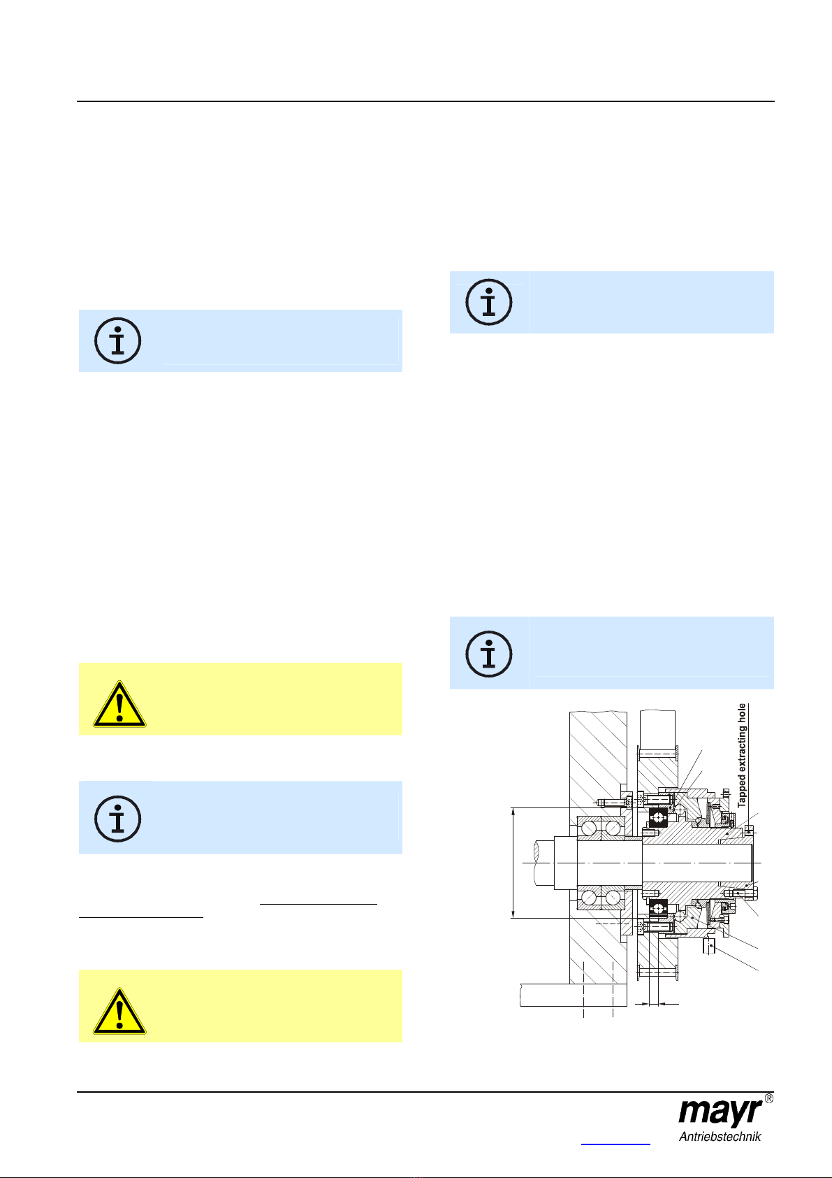
Installation of the Output Elements (Fig. 4)
The output element is centred on the deep groove ball bearing
(8) (tolerance H7/h5) and screwed together with the pressure
flange (2).
Please observe the maximum screw-in depth
in the pressure flange (Item 2 / Fig. 1 and
Table 3).
If the resulting radial force from the output element is anywhere
near the centre of the ball bearing (8) and under the max.
permitted radial load acc. Table 4, an additional bearing for the
output element is not necessary.
No appreciable axial forces (see Table 4) should be
transferred from the output element onto the clutch
pressure flange (2).
For extremely wide output elements or for elements with a small
diameter, we recommend the EAS®-Compact®with long
protruding hub (Type 490._ _ 4.1).
On very small diameters, the output element is screwed together
with the clutch pressure flange (2) via a customer-side
intermediate flange.
Ball bearings, needle bearings or bearing bushings are suitable
as bearings for the output element, depending on the installation
situation and the installation space.
In order to prevent the output element (pressure flange (2))
from moving axially in the direction of the thrust washer (3)
during overload, please make sure that the bearing of the
output element is designed as a location bearing (Fig. 4).
Please observe the connection dimensions "a"
and "e" for the output elements acc. Fig. 4 and
Table 5, page 3.
Fig. 4
Type 490.624.0
1
3
a