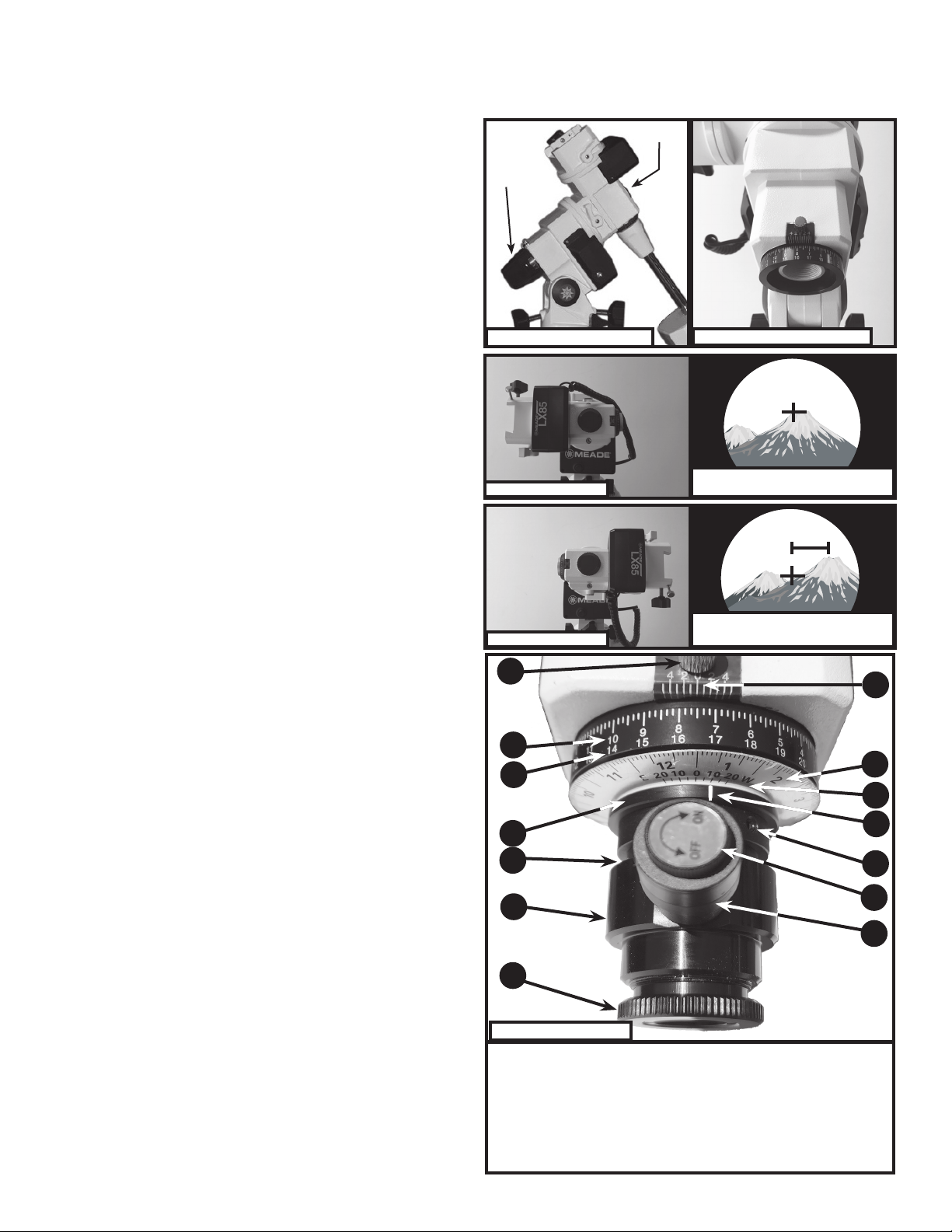
To calibrate the dials and indicators:
1. Unlock the RA setting circle locking screw(Figure 5, #1) and position the
RA setting circle dial (Figure 5, #3) until the 0 mark is aligned with the RA
setting circle indicator (Figure 5, #2). Re-tighten the locking screw.
2. Look through the polar scope and note the reticle crosshair. Unlock the
RA axis and rotate the RA until the 40/60 line is vertical as shown in Figure
6. Re-lock the RA axis.
3. Now adjust the calendar dial (Figure 5, #4) so the large line between the
10 & 11 is aligned with the mount RA indicator (see Figure 7).
Note: The calendar dial is numbered 1-12 with the longest lines separating
the months. The short lines are two days apart and medium sized lines are
ten days apart.
4. With the RA in this position, the Longitude-offset scale indicator (Figure
5, #6) needs to be aligned with the 0 mark on the Calendar-dial (Figure 5,
#4).
If it is not aligned with the calendar dial 0 mark, use a tiny flat head screwdriver
(user supplied) to loosen the Longitude indicator locking set-screw and align
the marks. Tighten the screw when aligned. When complete the reference
dials should appear as in Figure 7.as in Figure 7.
The dials and reticle pattern are now adjusted for a specific calendar date and
time where Polaris is directly above the North Celestial Pole (NCP) crossing
the meridian. This occurs at midnight on November 1st. The “Polaris” mark in
the reticle was placed at the bottom of the viewfinder field of view since the
polar scope image is inverted.
Adjust for Site Longitude:
Depending on your observing site longitude, you may need to further adjust
the Calendar-dial scale (see Figure 5, #4) to compensate for your site
longitude. First determine your observing site longitude by looking at a map,
GPS, or the internet. You will also need to determine the reference time zone
meridian for your time zone. For observers in the USA, see Figure 9. This
can also be found using the internet. Once both values are known, subtract
your site longitude from the reference time zone meridian to determine the
longitudinal-offset needed.
Reference Time Zone Meridian - Observing Site Longitude = Longitudinal-Offset
If the longitudinal-offset is a positive value, you’re East of the reference
meridian. If the longitudinal-offset is a negative value, you’re West of the
reference meridian.
For example: The longitude in Watsonville, California is 121.76° West. The
reference time zone meridian for the Pacific Time zone is 120°.
120° - 121.76° = -1.76° West
To compensate for this longitudinal-offset, the Calendar-dial scale(Figure 5,
#4) will be adjusted. Note each line on the longitude-offset scale is 5° apart.
Therefore, the longitudinal-offset scale should be adjusted to 1.8° West,
between the 0 mark and first line right of the 0 mark (see Figure 8). Do not
change this longitudinal-offset unless your observing sites differ significantly
in longitude.
Using the Polar Scope:
Now that the polar scope is aligned to the polar axis and dial indicators
properly calibrated (if desired), the polar scope is ready for use in obtaining
a precise polar alignment.
1. At night, fully assemble your LX85 and point it to True North.
2. Remove both polar scope front and rear covers. See Figure 1.
3. Rotate DEC to 90 (ota looking forward) so you can view through the
polar axis.
4. Unlock the RA axis and rotate it so the current time on the RA setting
circle (Figure 5, #3) is aligned with the current date on the calendar dial (Figure
5, #4). Note all times are in standard time and daylight saving times should not
be used. Lock the RA. Remember the top row of numbers on the RA setting circle
are for Northern Hemisphere users. The bottom row of numbers on the RA setting
circle are for Southern Hemisphere users.
5. For Northern Hemisphere: Move the telescope mount using the azimuth and
latitude controls until Polaris (the North Star) is placed within the reference circle
on the 40/60 reticle line. The center crosshair denotes the location for the North
Celestial Pole (NCP). It may be helpful to turn on the illuminated reticle feature by
rotating the power switch (see Figure 5, #12). Adjust the brightness to its lowest
level where you can still see the reticle clearly. Don’t forget to power off the reticle
when done.
6. For Southern Hemisphere: Move the telescope mount using the azimuth and
latitude controls until the four-sided figure in the reticle are superimposed on the
four star group in the southern night sky. The grouping of four stars in Octans
(Sigma, Tau, Chi, and Upsilon) are the closest reference objects near the South
Celestial Pole (SCP) and are often used in obtaining a precise polar alignment.
It may be helpful to turn on the illuminated reticle feature by rotating the power
switch (see Figure 5, #12). Adjust the brightness to its lowest level where you can
still see the reticle clearly. Don’t forget to power off the reticle when done.
Note: Not all pointing positions are possible with the polar alignment reticle, as the
tripod is a limiting factor as to how far the optical tube and mount can be moved.
7. Once the celestial pole is centered, tighten the latitude and azimuth adjustment
knobs. The mount is now precisely aligned on the night sky. Remember to replace
the polar scope covers to protect the polar scope and turn off the illuminated
reticle.
© 2022 Meade Instruments reserves the right to change product specifications or to discontinue product without notice.
14-2729-00 Rev 01
Figure 8: Longitude-oset scale adjusted 1.76 degrees West for Watsonville, CA.
Figure 7: Calibrated dialsFigure 6: Polar scope reticle
Time Zone Reference Time Zone Meridian
Hawaiian 150° West
Alaskan 135° West
Pacific 120° West
Mountain 105° West
Central 90° West
Eastern 75° West
Atlantic 60° West
Figure 9: Reference time zone meridians for the USA
2
Place Polaris here
Place Octans stars here