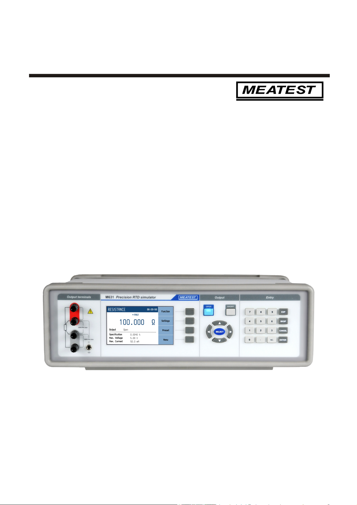
M631 Precision RTD Simulator MEATEST
3 Revision 22, FW 2.000 Operation manual
Content
1. BASIC INFORMATION....................................................................................................................... 5
2. PREPARATION FOR USE .................................................................................................................. 5
2.1. INSPECTING PACKAGE CONTENTS, SELECTING THE INSTALLATION LOCATION ..................................... 5
2.2. POWER ON ...................................................................................................................................... 5
2.3. WAR -UP TI E .............................................................................................................................. 6
2.4. SAFETY PRECAUTIONS ..................................................................................................................... 6
3. DESCRIPTION ..................................................................................................................................... 7
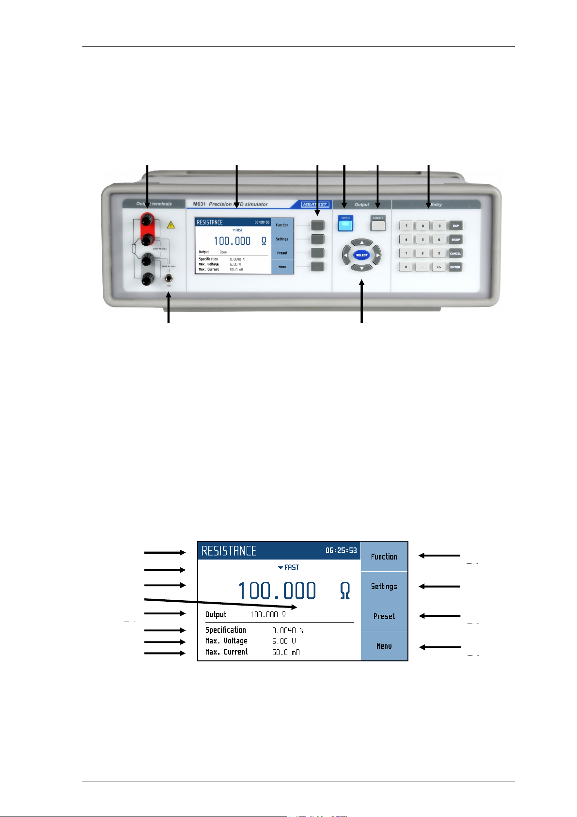
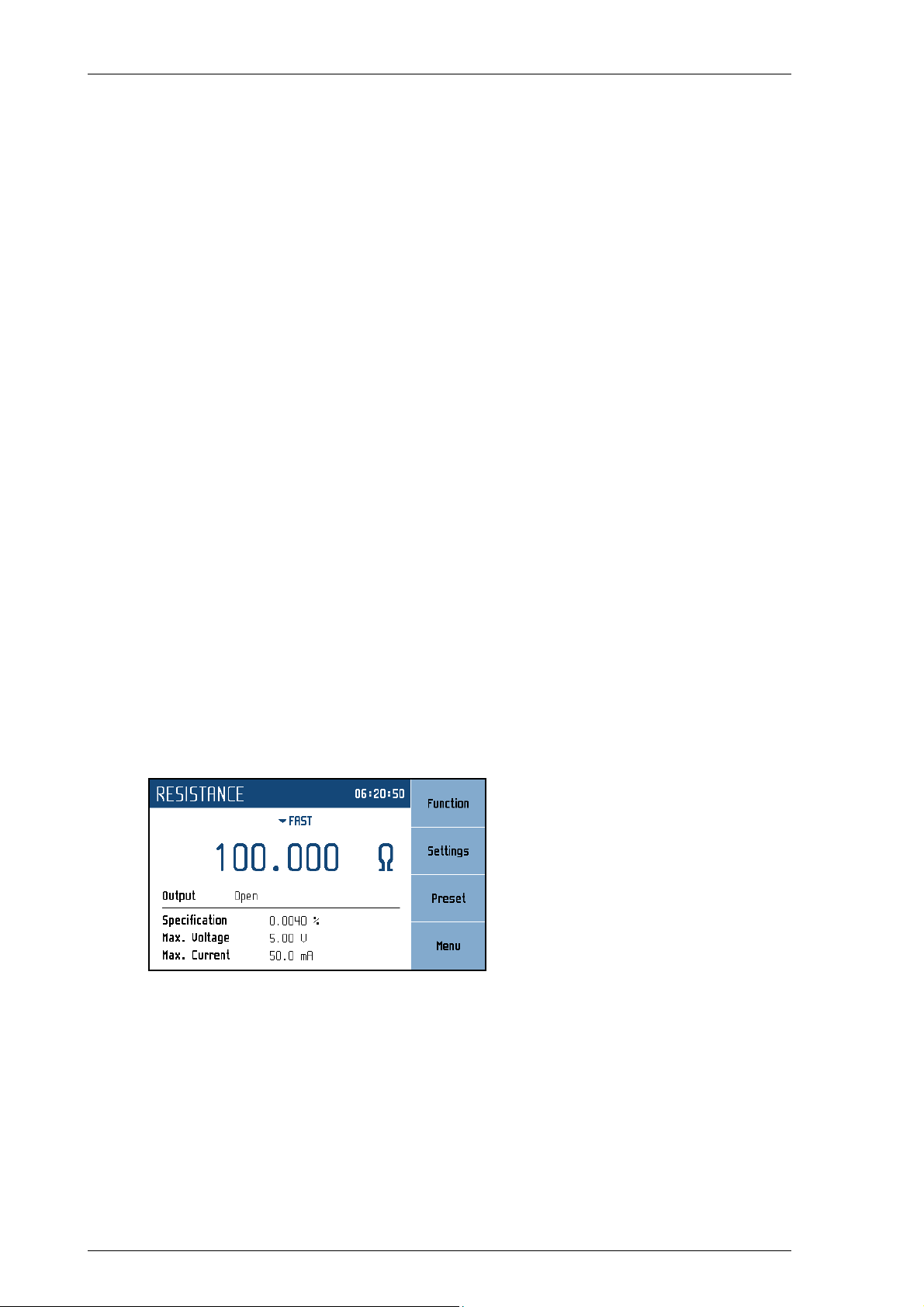
3.1. FRONT PANEL ................................................................................................................................. 7
3.2. REAR PANEL ................................................................................................................................... 9
4. OPERATION .......................................................................................................................................10
4.1. CONNECTION AND DISCONNECTION OF OUTPUT TER INALS .............................................................10
4.2. WIRES CONNECTION .......................................................................................................................10
4.3. SETTING THE FUNCTION .................................................................................................................10
4.4. SETTING THE VALUE OF OUTPUT SIGNAL .........................................................................................17
4.5. PARA ETER SETTINGS (SETTINGS ENU) ........................................................................................18
4.6. PRESET ENU ................................................................................................................................18
4.7. AIN ENU ...................................................................................................................................19
4.8. CALIBRATION ODE ......................................................................................................................21
5. PERFORMANCE VERIFICATION TEST ........................................................................................24
6. REMOTE CONTROL .........................................................................................................................25
6.1. RS232 INTERFACE .........................................................................................................................25
6.2. GPIB INTERFACE (OPTION) ............................................................................................................26
6.3. LAN INTERFACE (OPTION) .............................................................................................................27
6.4. USB INTERFACE (OPTION) ..............................................................................................................28
6.5. CO AND SYNTAX .......................................................................................................................29
6.6. SCPI CO AND TREE ...................................................................................................................30
6.7. STANDARD STATUS DATA STRUCTURES .........................................................................................32
6.8. SCPI STANDARD CO ANDS ........................................................................................................34
6.9. SCPI CO ANDS ..........................................................................................................................38
6.10. SCPI ERROR CODES .......................................................................................................................63
6.11. CO PATIBLE CO ANDS ..............................................................................................................64
6.12. DE O PROGRA ............................................................................................................................65
7. MAINTENANCE .................................................................................................................................66
7.1. FUSE REPLACING ............................................................................................................................66
7.2. EXTERNAL SURFACE CLEANING ......................................................................................................66
8. MODULE 19” (VERSION M631 VXX1X)..........................................................................................66
9. TECHNICAL DATA ............................................................................................................................67
10. ORDERING INFORMATION – OPTIONS .......................................................................................69
CERTIFICATE OF CONFORMITY ...........................................................................................................70