Meatest 9010 User manual

meatest
9010 Multifunction Calibrator
user manual
EN, rev. 1
7


3 Meatest 9010 User Manual
Content
1.
Introduction..................................................................................................................................................... 6
Front panel overview.................................................................................................................................................................. 6
Rear panel overview ................................................................................................................................................................. 10
Options and accessories ........................................................................................................................................................ 10
Remote control ............................................................................................................................................................................ 11
2.
Getting started ..............................................................................................................................................12
Safety precautions ..................................................................................................................................................................... 1
Power on and warm-up ..........................................................................................................................................................13
Function setup ............................................................................................................................................................................. 14
Signal output ................................................................................................................................................................................ 14
3.
Menu reference ............................................................................................................................................. 15
Information menu ..................................................................................................................................................................... 15
Device menu ................................................................................................................................................................................. 16
System menu................................................................................................................................................................................ 16
Interface menu ............................................................................................................................................................................ 16
Calibration menu ....................................................................................................................................................................... 17
Preset menu .................................................................................................................................................................................. 17
4.
Cali ration examples ................................................................................................................................ 18
AC/DC Voltage ............................................................................................................................................................................. 18
AC/DC Current.............................................................................................................................................................................
Resistance ...................................................................................................................................................................................... 4
Capacitance .................................................................................................................................................................................. 7
Electric power meters, analyzers and energy meters ........................................................................................ 8
SCO scope extension ................................................................................................................................................................31
Temperature sensor simulation ........................................................................................................................................ 34
MER multimeter extension..................................................................................................................................................36
5.
Performance verification ........................................................................................................................ 40
Required equipment .............................................................................................................................................................. 40
Verification procedure ........................................................................................................................................................... 40
Test points ...................................................................................................................................................................................... 41
6.
Adjustment .................................................................................................................................................... 45
Calibration menu structure ................................................................................................................................................ 45
Calibration point adjustment ............................................................................................................................................ 46
List of calibration points .........................................................................................................................................................47
7.
Maintenance ................................................................................................................................................... 51
Fuse replacement ...................................................................................................................................................................... 51
External surface cleaning ...................................................................................................................................................... 51
Firmware update ........................................................................................................................................................................ 51
Error messages............................................................................................................................................................................ 5
8.
Specifications ............................................................................................................................................... 53
Voltage ............................................................................................................................................................................................. 54
Current ............................................................................................................................................................................................. 56

Meatest 9010 User Manual 4
Resistance.......................................................................................................................................................................................58
Capacitance ................................................................................................................................................................................. 60
Power and energy ..................................................................................................................................................................... 61
Harmonics ...................................................................................................................................................................................... 63
Temperature sensor simulation........................................................................................................................................ 63
SCO 400 MHz scope option ................................................................................................................................................65
MER integrated multimeter option ............................................................................................................................... 67
Certificate of conformity ................................................................................................................................... 69
List of ta les
Table 1 Integrated options ............................................................................................................................................................................11
Table Scope option modes ..................................................................................................................................................................... 31
Table 3 Multimeter SETUP .......................................................................................................................................................................... 39
Table 4 List of main test points ................................................................................................................................................................ 43
Table 5 List of options’ test points .......................................................................................................................................................... 44
Table 6 Calibration points – DC voltage and current ................................................................................................................. 47
Table 7 Calibration points – AC voltage and current ................................................................................................................. 48
Table 8 Calibration points – Resistance ..............................................................................................................................................49
Table 9 Calibration points – Capacitance ..........................................................................................................................................49
Table 10 Calibration points – HVR option ......................................................................................................................................... 50
Table 11 Calibration points – SCO option ........................................................................................................................................... 50
Table 1 Calibration points – MER option ......................................................................................................................................... 50
Table 13 Error code overview ..................................................................................................................................................................... 5
List of figures
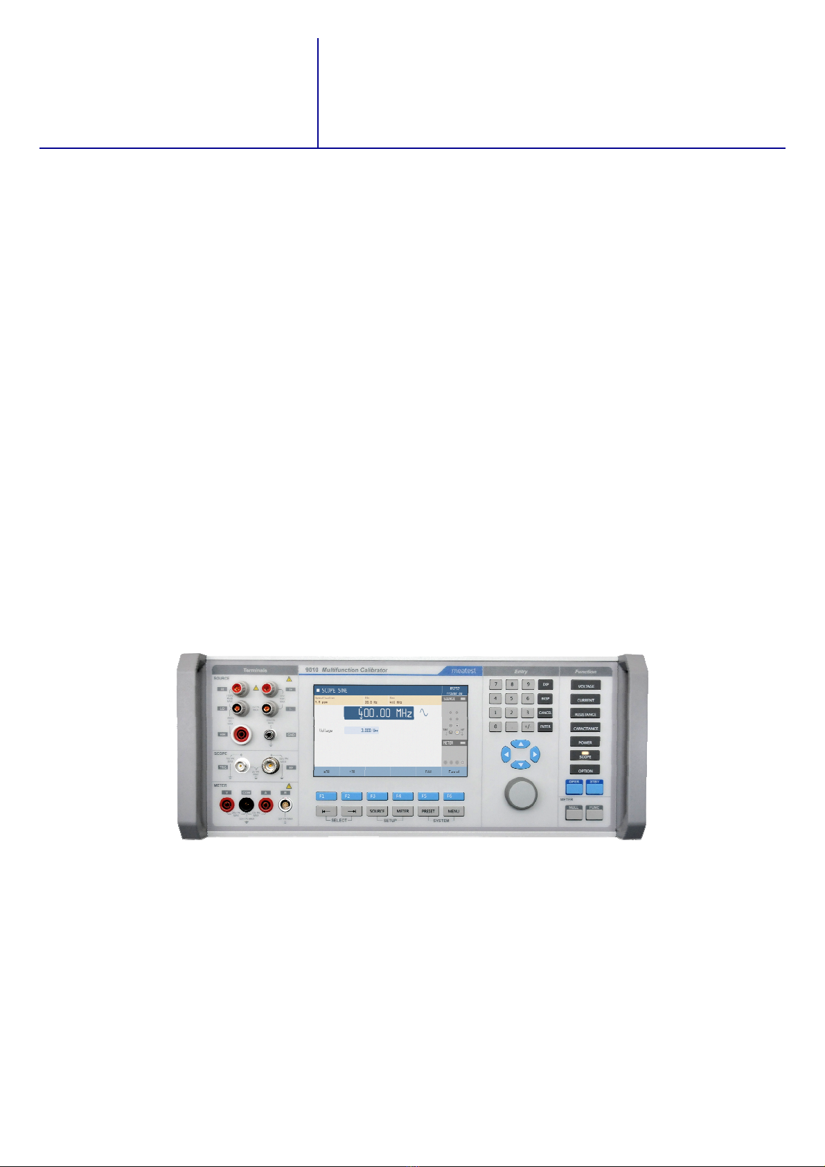
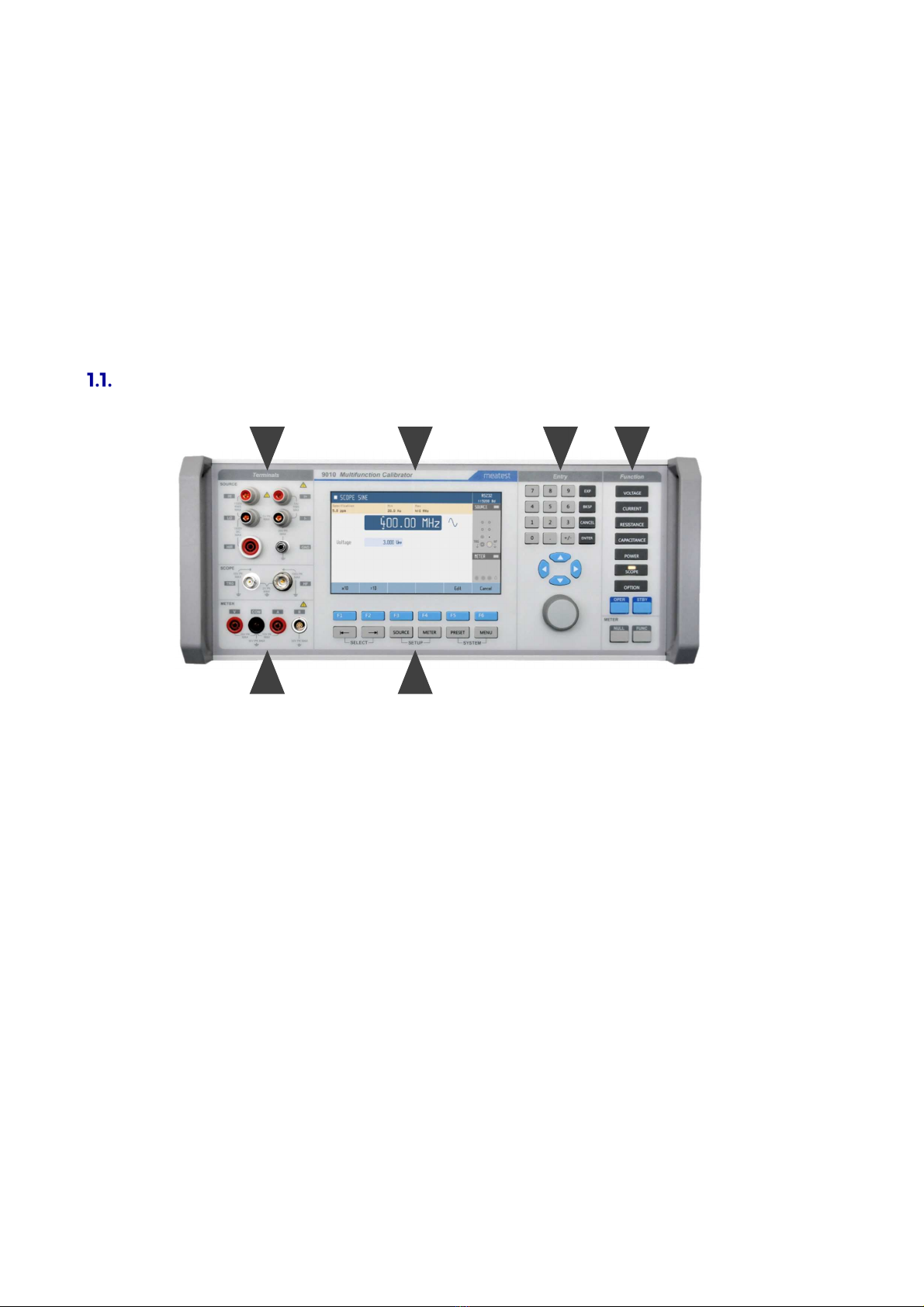
Figure 1 Front panel ........................................................................................................................................................................................... 6
Figure Input/output terminals ................................................................................................................................................................ 7
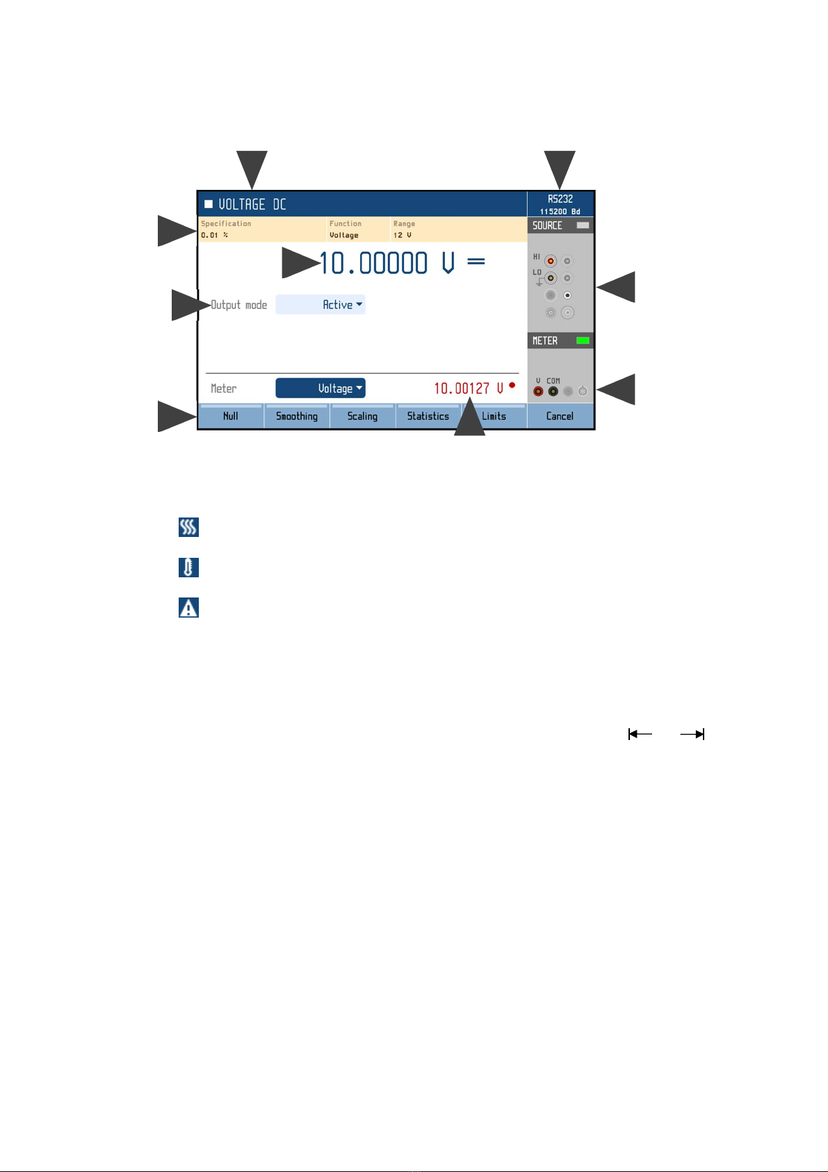
Figure 3 Display .................................................................................................................................................................................................... 8
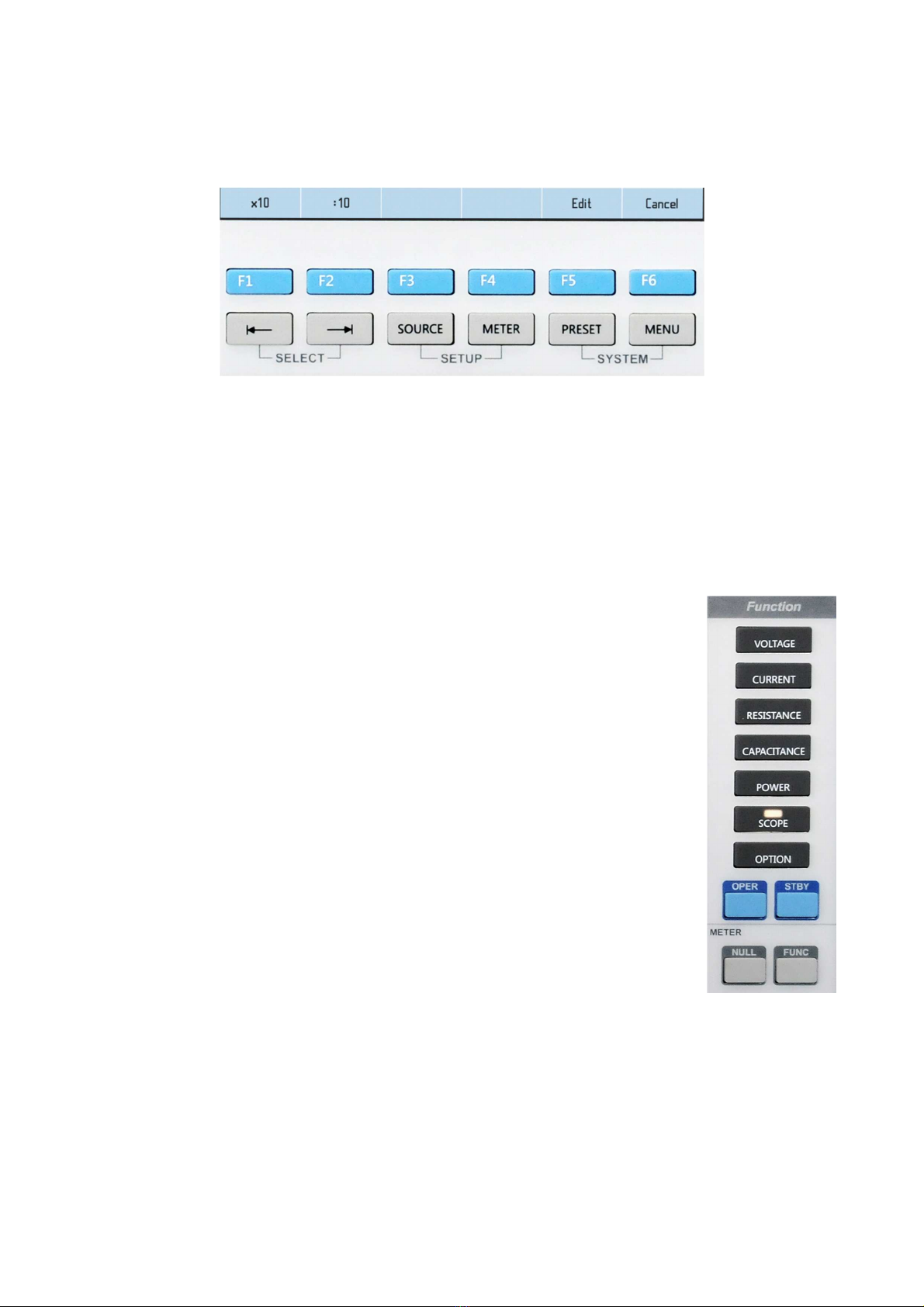
Figure 4 Softkeys and menu buttons ..................................................................................................................................................... 9
Figure 5 Function buttons ............................................................................................................................................................................. 9
Figure 6 Rear panel ......................................................................................................................................................................................... 10
Figure 7 Starting Screen ................................................................................................................................................................................ 13
Figure 8 Factory default screen ................................................................................................................................................................ 13
Figure 9 Main and auxiliary parameters ..............................................................................................................................................14
Figure 10 Main menu ....................................................................................................................................................................................... 15
Figure 11 Device/Setup menu .................................................................................................................................................................... 16
Figure 1 Preset function ............................................................................................................................................................................... 17
Figure 13 Voltmeter calibration ................................................................................................................................................................ 18
Figure 14 Harmonic products setting ................................................................................................................................................... 19
Figure 15 Signal preview ............................................................................................................................................................................... 19
Figure 16 List of preset waveforms ........................................................................................................................................................ 0
Figure 17 Voltage SETUP screen ............................................................................................................................................................... 1
Figure 18 Ammeter calibration ................................................................................................................................................................
Figure 19 Current SETUP screen .............................................................................................................................................................. 3
Figure 0 Two-wire resistance calibration ........................................................................................................................................ 4
Figure 1 Four-wire resistance calibration ......................................................................................................................................... 5
Figure High resistance calibration .................................................................................................................................................. 6

5 Meatest 9010 User Manual
Figure 3 Capacitance calibration......................................................................................................................................................... 7
Figure 4 AC Power ........................................................................................................................................................................................ 8
Figure 5 Power meter calibration ....................................................................................................................................................... 8
Figure 6 Harmonic mode ......................................................................................................................................................................... 9
Figure 7 Energy mode ................................................................................................................................................................................ 9
Figure 8 Power/Energy soft keys .......................................................................................................................................................... 30
Figure 9 Energy mode ................................................................................................................................................................................ 30
Figure 30 Scope option ..................................................................................................................................................................................31
Figure 31 SCO option Device/Setup menu ........................................................................................................................................ 33
Figure 3 RTD temperature sensor simulation .............................................................................................................................. 34
Figure 33 TC temperature sensor simulation .................................................................................................................................. 35
Figure 34 TC External cold junction compensation using Adapter 91 ............................................................................ 35
Figure 35 Process multimeter ...................................................................................................................................................................36
Figure 36 Thermocouple output through 91 Adapter ...............................................................................................................36
Figure 37 Multimeter softkeys ................................................................................................................................................................... 37
Figure 38 Meter smoothing filter............................................................................................................................................................. 37
Figure 39 Meter statistics function ........................................................................................................................................................ 38
Figure 40 Meter limits function............................................................................................................................................................... 38
Figure 41 Password entry ............................................................................................................................................................................. 45
Figure 4 Calibration menu with out-of-date calibration data .......................................................................................... 45
Figure 43 Calibration point adjustment – direct ........................................................................................................................... 46
Figure 44 Calibration point adjustment – indirect ...................................................................................................................... 46

Meatest 9010 User Manual 6
1.
Introduction
Multifunction calibrator 9010 is designed as universal calibration tool for electrical calibration
laboratories, covering most of their workload like multimeters, clamp meters, ohm meters, power meters
and power analysers, energy meters, transducers, insulation testers, process meters, scopes and many
others. High load capacity of voltage output (up to 0 mA) allows for calibration of high-consumption
analogue meters. Installed harmonic and non-harmonic shape signals allow for testing meter sensitivity
to distorted signals by a signal with various crest factor.
Advancing from previous M14x calibrator series, 9010 can now calibrate even 400 MHz scopes, 1. kV
insulation testers and 1 MW power meters. On the other hand we kept all the popular functions including
complete transducer and external sensor calibration (strain gauge, pressure, torsion, force, etc.) using
built-in multimeter, automatic uncertainty calculation, remote control and easy recalibration.
Front panel overview
Main control segments of the calibrator (Figure 3) are:
Figure 1 Front panel
1. Output terminals
2. Display
3. Numeric and navigation keys
4. Function keys
. Input terminals
6. Softkeys (sky blue) and menu keys (grey)
5
1
6
3
4

7 Meatest 9010 User Manual
1.1.1. Terminals in detail
All input and output terminals are located on left side of front panel. Labels between terminals show
overall maximum voltage ratings in standby. Maximum voltage ratings during operation are usually
lower and exceeding them might cause damage to the calibrator! See Specifications for detailed ratings.
Figure 2 Input/output terminals
1. HI. Outputs set voltage in VOLTAGE and POWER functions, set resistance in 2W mode of
RESISTANCE and CAPACITANCE functions and force signal in 4W RESISTANCE mode.
All signals are relative to LO.
2. I+. Outputs set current in CURRENT and POWER functions and senses RESISTANCE in 4W
mode. All signals are relative to I-.
3. LO. Acts as zero potential in VOLTAGE, POWER, 2W RESISTANCE, 2W CAPACITANCE
and HVR functions. Also provides zero potential to force signal in 4W RESISTANCE mode.
4. I-. Acts as zero potential in CURRENT and POWER functions. Also provides zero potential to
sense signal in 4W RESISTANCE mode. I- terminal is floating up to 20 V
pk
relative to the
Ground, SETUP menu allows you to ground this terminal with relay.
. HIR. Outputs set resistance in HVR function (option HVR).
6. GND. Ground potential, galvanically connected with housing and mains PE wire.
7. TRG. Used as external trigger for SCOPE functions (option SCO).
8. SCO. Outputs all SCOPE function signals through N-type coaxial connector (option SCO).
9. V. Measures voltage and frequency signals in METER function, relative to COM (option MER).
10. COM. Acts as zero potential for all METER functions (option MER).
11. A. Measures current signals in METER function, relative to COM (option MER).
12. R. Connector for 9000-60 Adapter and 91 Cold Junction Compensator only, don‘t connect any
other cables to this terminal! 9000-60 adapter is used for measurement of RTDs and 4W
resistance in METER function (option MER), 91 adapter is used for cold junction compensation
of thermocouples. Adapter terminals are described on the adapters themselves.
1
3
5
7
9
4
6
8
10
11
1

Meatest 9010 User Manual 8
1.1.2. Display in detail
Display is divided into several sections with following meaning:
Figure 3 Display
1. Selected function. Symbol on the left indicates system status ( standby, settling in, ►
running). There may be additional Warning symbols on the right:
a. Warm-up in progress. Calibrator is fully operational but it may be outside
specifications.
b. Overheated. Output terminals cannot be switched on until temperature falls below
safe limit. Set 10V DC and wait a few minutes until the symbol disappears.
c. Other error. Some functions may not be operational and/or outside specifications.
Go to “MENU/Information/Device status” to get detailed information.
2. Tooltip. Shows additional information about selected parameter or main value. Information may
include uncertainty, range, description, limits (burden current, compliance voltage), etc. Tooltip
is hidden when no parameter is selected.
3. Main value. Can be edited via numerical input, cursor keys or rotary knob. Symbol on the right
represents signal shape.
4. Auxiliary parameters. You can switch between parameters (and main value) using and
buttons. Every function has different set of auxiliary parameters.
. Softkey labels. Softkeys below the display change their function dynamically based on current
workspace, these labels describe Softkey functions at any given time.
6. Remote control. Shows active interface and its main parameter.
7. Output status. Indicates output status (grey means OFF, green means ON) and shows diagram
of active output terminals.
8. Input status. Indicates meter status (grey means disconnected, green means measuring) and
shows diagram of active input terminals.
9. Meter reading. Meter function can be changed using FUNC button in METER group.
5
7
8
4
3
1
6
9

9 Meatest 9010 User Manual
1.1.3. Keys in detail
There are 3 button groups in total on the front panel. Softkeys and menu buttons under the display,
function buttons on the right and numeric entry buttons with rotary knob and cursor buttons in between.
Figure 4 Softkeys and menu uttons
1. SELECT. Selects previous/next parameter on display. Selected parameter can be edited and
relevant tooltip is shown (if enabled). Press CANCEL to deselect a parameter.
2. SETUP. Enters/exits device menu. Device menu contains additional function parameters, see
chapter 3.2 or SETUP subchapters in chapter 4 for more details.
3. SYSTEM. Enters/exits main menu. Main menu contains all device-related settings, see menu
structure in chapter 3.
4. Softkeys. Buttons with context-specific functions. Current functions are shown on display, just
above the buttons.
Entry uttons
1. Function buttons. Directly selects a calibrator function or toggles
function mode if the function is already selected (f.e. pushing
VOLTAGE button in voltage DC mode switches to voltage AC mode.
2. OPER. Turns output on according to selected function and parameters.
3. STBY. Turns output off.
4. NULL. Sets meter readout to zero by shifting offset of active meter
function.
. FUNC. Toggles meter function.
Figure 5 Function uttons
Entry uttons
Numeric and navigation buttons have dual function. In menus these buttons are used to list through items
( and buttons, knob rotation), select an item (ENTER button, OK softkey or knob push), enter a
value or exit menu item (CANCEL button, EXIT/CLOSE softkey).
Outside menus, numeric and navigation buttons are used to edit values of selected parameters. If no
parameter is selected, pressing any numeric or navigation button will select function’s main parameter.
Values can be edited with cursor keys and rotary knob as well. Use ⊳ and buttons to shift through
digits and and buttons to increment or decrement that digit. Knob rotation works as either /
or ⊳ / buttons, knob push toggles between the two modes.

Meatest 9010 User Manual 10
Rear panel overview
There is located power line entry module with power line fuse, power line voltage selector 11 /230V
and power line switch. On the bottom side interface connectors RS-232, SPS and optionally LAN, USB
and IEEE488 on the rear panel.
Figure 6 Rear panel
1. Power cord module with power switch, fuse holder and 11 /230 V voltage selector
2. RJ-4 (Ethernet) connector for remote control
3. USB connector for remote control
4. GPIB IEEE-488 connector for remote control
. RS-232 connector
6. External signal synchronization input
7. External signal synchronization output
8. SPS connector A for external calibrator modules
9. SPS connector B for external calibrator modules
10. Fan outlet cover
Options and accessories
Every 9010 Multifunction Calibrator delivery includes following items:
- USB stick with user manual
- Factory calibration certificate
- Power cord (with European E-type plug, feel free to ask for other types when ordering)
- 2x spare fuse (3.1 A, 6.3A)
- RS232 cable
- Test leads, rated for 600V/32A
Following accessory is not part of standard delivery and can be extra ordered:
- Option 91 Pt100 Cold junction compensator
- ISO1702 calibration certificate
- 3, 4 or -year extended warranty
9010 Multifunction calibrator can be ordered with integrated options as listed in Table 1. Integrated
options can be fitted only by manufacturer and certified service providers.
1
3
4
5
6
7
8
9
1
0

11 Meatest 9010 User Manual
Option Description Additional accessory
SCO Scope extension for calibration of oscilloscopes up to
400 MHz. N/BNC Coaxial adapter
HVR High voltage resistance extension for calibration of
insulation testers on megaohmmeters up to 1.5 kV. 191-11 Cable for HV measurement up to 5 kV
MER Multimeter extension for calibration of transducers and
simulation of strain gauges and other industrial sensors.
9000-60 Cable adapter for R4W/RTD
measurement
Ta le 1 Integrated options
Remote control
The calibrator can be integrated into automated calibration systems (ATS) and generally controlled from
remote computer via following remote control interfaces:
- RS232
- USB
- GPIB (IEEE488)
- LAN
When controlled remotely, maximum ratings of calibrator’s output signals as well as all other
specifications are the same as in manual mode.
Meatest software package WinQbase + Caliber is recommended for best automation results. This system
is designed for automated and semi automated calibrations of digital and analogue meters including
uncertainty calculation, result evaluation and certificate printing according to ISO 1702 standard.
1.4.1. Connection setup
Only one interface can be used for communication at any given time. Default active interface is RS232,
other interfaces can be selected in MENU->Interface->Active bus. To establish connection between the
calibrator and computer, set interface settings in your computer accordingly:
RS232 and USB connection settings
- COM port see available COM ports in Windows Device Manager
- Baudrate USB 9600
- Baudrate RS232 according to MENU->Interface->RS232 Baudrate (9600 by default)
- Data bits 8
- Stop bits 1
- Parity None
- Handshake (XON/XOFF) Off
GPIB connection settings
- GPIB Address according to MENU->Interface->GPIB Address (2 by default)
LAN connection settings
DHCP service discovery is active by default and is recommended for easiest connection. If you prefer
to use fixed IP address or change any other default settings, go to MENU->Interface->LAN Settings.
LAN communication uses Telnet protocol. Default log-in for Telnet client is “9010_SNxxxxxx 23”,
where “xxxxxx” stands for serial number and 23 is default communication port.
1.4.2. SCPI commands and protocol
See 9010 SCPI manual for complete SCPI reference, more details on communication setup and
troubleshooting.

Meatest 9010 User Manual 1
2.
Getting started
Inspect package contents when unboxing the calibrator for the first time. See chapter 1.3 for complete
list of accessories.
Place the instrument on a level surface before powering on and let it stabilize for at least one hour if the
instrument has been stored outside of reference temperatures beforehand.
Safety precautions
The instrument has been designed according to IEC 61010-1:2011 + A1. Safety is ensured by design
and by use of specific components. The manufacturer is not liable for the damage caused by modification
of the construction or replacement of parts with non-original ones.
Safety symbols used on the equipment:
Warning, risk of danger.
Warning - risk of electric shock. Hazardous voltage above 0 V DC
or AC might be present.
See User Manual.
Protective earth.
Fuse.
To prevent possible electrical shock or personal injury:
- Read carefully safety information before you use the Product.
- Do not alter the Product and use only as specified, or the protection supplied by the Product can be
compromised.
- Do not use the Product if it is altered or damaged.
- Use this Product indoors only.
- Use power cord approved for local mains voltage and plug configuration and rated for the Product.
- Use test leads rated for at least 1000 V and 20 A in all core functions and at least 2000 V in HVR
high voltage resistance function.
- Keep hands away from all Product terminals and exposed metal cable parts during operation. High
voltage on those may be cause death or serious injury.

13 Meatest 9010 User Manual
Power on and warm-up
The calibrator must be powered by 230/11 V – 0/60 Hz mains. Before connecting the instrument to
the mains, check the position of the mains voltage selector located on the rear panel. Set appropriate
voltage selector position either 11 V or 230 V.
Plug one end of the power cord into connector on the rear panel and connect the other end of the power
cord into a wall outlet. Turn the calibrator on with mains switch right next to it. You should see following
splash screen on display.
Figure 7 Starting Screen
Calibrator then performs internal hardware checks for app. seconds and then starts in Startup state
(called Preset). Startup preset can be customized and up to 99 other presets can be defined and recalled
later at any time. By default the Startup preset is set to VDC function, 10 V with output switched off.
Warm-up
Specified parameters are guaranteed 30 minutes after switching the calibrator on and stabilizing it in
reference conditions.
Figure 8 Factory default screen

Meatest 9010 User Manual 14
Function setup
Calibrator output (source) function can be set using FUNCTION buttons. Push any FUNCTION button
to change function or push the button repeatedly to scroll through function modes if available (for
example DC and AC in voltage function.
Once a function is selected, you can change the main value as well as auxiliary output parameters like
frequency in AC modes or phase shift in AC power function. Function parameters can be edited in three
ways:
- Numeric keypad. Write a value directly and confirm either by softkey with appropriate unit or
ENTER button to set value in base unit (for example V).
- Cursor keys and rotary button. Push buttons or turn rotary knob to increment/decrement
selected digit by one. Move through parameter digits using ⊳ buttons or push the rotary knob
to switch to digit selection mode, rotate to a new digit and confirm with another push.
- Softkeys. Values of most parameters can be also changed by softkeys x10 and :10, which change
value by order of magnitude and +/- softkey which switches polarity.
Figure 9 Main and auxiliary parameters
Described methods change the main parameter by default. If there are any other parameters on display,
you can switch between them using and select buttons. Picture above shows AC voltage function
with main value 10 V
rms
and two auxiliary parameters: signal shape and frequency. Both auxiliary
parameters have their dedicated softkey for fast access.
Additional settings are available under setup buttons SOURCE and METER. These buttons are shortcuts
to relevant sections of Device menu. See chapter 3.2 or SETUP subchapters in chapter 4 for more details.
Signal output
Calibrator output can be turned on by pushing OPER button. STBY button turns output off. Output turns
off automatically on calibrator startup and function switch. Output state is indicated by LED light in
OPER button as well as green rectangle next to Source label on the right side of the display. Diagram
below Source label shows which terminals are currently being used.
Signal input
With MER option installed you can also take advantage of integrated multimeter and its measurement
capabilities. Meter input can be activated and deactivated by pushing FUNC button. Similarly to
calibrator output, meter input state is indicated by LED light in FUNC button and green rectangle next
to Meter label.

15 Meatest 9010 User Manual
3.
Menu reference
Four buttons on the front panel give access to main menu sections:
- Source. Shortcut to section of Menu > Device related to currently selected source function.
- Meter. Shortcut to Menu > Device > Meter
- Preset. Save or recall predefined calibrator configurations. See chapter 3.6 for more details.
- Menu. Access to main menu.
Figure 10 Main menu
Main menu is the most comprehensive setup tool of the calibrator, containing information like serial
number, calibration date or display brightness as well as remote control interface setup or calibration
constants.
Short tooltip in yellow box shows basic description of selected item. Main menu items are described in
detail in chapters 3.1 – 3. .
Information menu
Information menu contains general device data which cannot be modified by the user:
-
Manufacturer
- Model
- Serial number
Device identification
-
Software version
- Hardware version
- Option installed
Device configuration
-
Expiration of Calibration validity
- Current date
- Device status
Device readiness info. Calibration
expiration date is equal
to last calibration date plus calibration interval, see menu
item Calibration for more details.
-
Testing tools
Display and keyboard diagnostics
-
Modules
List of internal electronic modules and their status

Meatest 9010 User Manual 16
Device menu
Device menu is divided according to calibrator functions and gives access to additional function related
settings. Sections of currently used functions can be accessed directly using SOURCE and METER
shortcut buttons on front panel. Picture below shows DC power section as an example of device menu.
Figure 11 Device/Setup menu
System menu
System menu contains general, user-accessible device settings:
- Language Language version of user interface
- Display backlight [0 – 100 %]
- Button light intensity [0 – 100 %]
- Beeper volume [0 – 100 %]
- Keyboard beep [On/Off]
- Show tooltips on display Turns yellow menu tooltip On/Off
- Form of specification [Auto/Absolute/%/ppm]
- Date & Time Password protected submenu with following items
o Time System time in HH:MM:SS format
o Date System date in selected format
o Format Date format [M/D/Y, M-D-Y, D/M/Y, D.M.Y,
D-M-Y, Y/M/D, Y.M.D]
o Show date & time on display [On/Off]
Interface menu
Interface menu contains remote control connection settings:
Menu item Range / format Default value
Active bus RS 3 /GPIB/USB/LAN RS 3
RS 3 Baudrate 1 00 – 115 00 9600
GPIB Address 0 – 31
USB Baudrate 1 00 – 115 00 9600
LAN Settings
> DHCP On/Off On
> IP Address IPv4 format; locked with DHCP On 19 .168.001.100
> Subnet mask IPv4 format; locked with DHCP On 55. 55. 55.000
> Default gateway IPv4 format; locked with DHCP On 55. 55. 55. 55
> Port number 0 – 9999 3
> Host name 14 alphanumeric characters; locked with DHCP Off M160_SN710011

17 Meatest 9010 User Manual
Cali ration menu
Calibration menu contains internal calibration constants and other tools for device adjustment and is
therefore password protected. See chapter 6 for more details on 9010 adjustment. Calibration menu has
following items:
1. Data. Contains current calibration data. Structure of this menu is described in chapter 6.1.
2. Backup. Calibration data backup. See below for more details.
3. Password. Changes calibration password. Calibration password gives access to Calibration
menu and Date/Time settings in Information menu.
4. Calibration date. Calibration date is updated automatically upon calibration data adjustment or
just by manual confirmation (if calibration doesn‘t require adjustment).
. Calibration interval. Recommended interval is 12 months.
Backup function allows you to save and recall entire sets of calibration data. Calibration data are also
saved automatically when any calibration value gets changed, creating a record with “Auto” storage (or
overwriting an existing one if the last change occurred within last 90 days). Use softkeys to save and
recall previously stored calibration data sets:
1. Back up. Saves currently used calibration data, overwriting existing record on selected Location.
Only empty records and records with Calibration access and Manual storage can be overwritten.
2. Try. Loads selected record temporarily, original calibration data will be restored on next
calibrator startup.
3. Load. Loads selected record permanently.
4. Delete. Deletes record. Only records with Calibration access and Manual storage can be deleted.
Preset menu
Preset feature allows you to save and recall one of up to 100 calibrator configurations so that you can
get to work quickly instead of setting up the calibrator every single time. Push PRESET button to show
list of saved presets:
Figure 12 Preset function
To recall a predefined configuration, select its preset the list a push Load softkey. Configuration will be
loaded with output turned off for safety reasons.
Similarly you can save a configuration by choosing Location 0 – 99 from the list and pushing Save
softkey. Preset includes configuration of:
- Function and mode (for example AC Power)
- Main value (for example 10 VA)
- Auxiliary parameters (for example 0 Hz, 10 V, 1 A, 0 °)
- Additional Device/Setup menu parameters of current Source and Meter function
Preset doesn’t include harmonic distortion parameters nor main menu settings except those mentioned
above.

Meatest 9010 User Manual 18
4.
Cali ration examples
AC/DC Voltage
4.1.1. DC and SINE Voltage
1. Connect the voltmeter to the calibrator as shown on the figure below.
2. Select appropriate function and range on the voltmeter
3. Push VOLTAGE function key on the calibrator. DC mode is automatically set. Push VOLTAGE
key once more if AC voltage is requested.
Figure 13 Voltmeter cali ration
4. In AC mode push SELECT function repeatedly to activate window Frequency and set requested
frequency.
. Set output voltage value using cursor keys, rotary button or numerical keyboard.
6. Switch output terminals on by pushing key OPER. Output voltage is presented on the output
terminals, OPER key is lit and indication SOURCE on the screen is green.
7. Push STBY key to switch output voltage off.
4.1.2. Non-sinusoidal Voltage
Calibrator can source non-sinusoidal waveforms with pre-defined shape. Frequency range for these
waveforms is limited from 10 mV to 200 V and frequency range from 40 Hz to 1 kHz. Following
waveforms are implemented:
- Limit. Sine sinusoidal with defined distortion 13. 22 %
- Square squarewave symmetrical
- Triangle symmetrical
- Ramp Up
- Ramp Down
- Harmonic adjustable harmonic products
To select requested waveform push the soft key SHAPE, highlight requested item using softkeys ,
cursor keys or rotary button and confirm with ENTER.
Terminals
HI
LO
I+
I-
HIR GND
Entry Function
TRG HF
9010 Multifunction Calibrator
V COM A R
METER
SCOPE
SOURCE
METER
NULL
SELECT SETUP SYSTEM
1100V
RMS
MAX
1500V
DC
MAX
1V PK
MAX
20V PK
MAX
1 00V PK
MAX
10V PK
MAX
2V PK
MAX
25V PK
MAX
10V PK
MAX
50V PK MAX 50 V PK MAX
FUNC
OPER S TBY
1 0V
RMS
MAX

19 Meatest 9010 User Manual
4.1.3. Harmonic
Calibrator has unique feature of creation by customer defined output AC signal. Definition on the signal
is based on setting of amplitude and phase shift of harmonic products related to basic, fundamental
frequency. Number of harmonic products is limited to 0 but maximum frequency of harmonic product
cannot exceed kHz. Amplitude of individual harmonic products cannot be higher than 10 % of
amplitude of fundament signal.
Harmonic product editing
1. Push the key SELECT to make active window Harmonic.
2. Push the EDIT soft key. Table with list of harmonic products appears. Set amplitude and phase
of requested harmonic product. Use key SELECT to move active window between Amplitude
and Phase.
3. When all harmonic products are set push soft key EXIT to return back to basic screen. Distortion
of sine wave signal has been adjusted.
Figure 14 Harmonic products setting
To reset all harmonic products setting use soft key CLEAR ALL. All higher harmonic products are set
to zero except fundamental component. When non-zero distortion is set, star sign will appear in window
Harmonic ahead Sine label.
To move between pages of harmonic products use soft keys PAGE UP and PAGE DOWN.
Signal preview
The formed signal can be displayed either in frequency or time domain.
Push the soft key Bar to display relative level of harmonic products setting in frequency domain.
Fundamental component is displayed in yellow, higher harmonics in red colour.
Push the soft key PREWIEV to see the signal waveform in time domain.
Figure 15 Signal preview

Meatest 9010 User Manual 0
Preset function
Any adjusted signal can be stored in the calibrator memory for later use. Use the NEW soft key to create
a new signal name. Use rotary button to select individual signs (numbers or letters) and confirm with
SAVE when finished.
Any already saved waveform can be loaded using soft key LOAD or deleted using soft key DELETE.
Figure 16 List of preset waveforms
4.1.4. Passive and Active Output
DC Voltage function has two kind of output on ranges 20 mV and 200 mV. Ranges 2 V, 20 V, 280 V
and 1000 V don’t have passive output.
Active output is formed by electronic amplifier. The output offers higher load current up to mA
however with a little bit worse uncertainty. Passive mode is formed by resistance divider with output
resistance 0 Ω. Output signal is less noisy and with better uncertainty however maximal output current
is given by its output impedance. See specification for detailed differences.
Push SELECT key until field Output mode is not activated. Change setting from Active to Passive using
soft key arrow keys, soft key List or rotary knob.
Table of contents
Other Meatest Test Equipment manuals

Meatest
Meatest MC641 User manual

Meatest
Meatest M133C User manual

Meatest
Meatest 9010+ User manual

Meatest
Meatest M133C User manual

Meatest
Meatest M-140 User manual

Meatest
Meatest M-142 Installation manual

Meatest
Meatest M525 User manual

Meatest
Meatest M631 User manual

Meatest
Meatest M143 User manual

Meatest
Meatest M505D User manual