Memjet AstroJet M1 User manual
AstroJetTM M1
COLOR PAGE
PRINTER
OPERATOR MANUAL
ASTRO MACHINE CORP.
630 Lively Blvd.
Elk Grove Village, IL 60007
Phone: (847) 364-6363
Fax: (847) 364-9898
www.astromachine.com

SAFETY PRECAUTIONS
THIS EQUIPMENT PRESENTS NO PROBLEM WHEN USED PROPERLY.
HOWEVER, CERTAIN SAFETY RULES SHOULD BE OBSERVED WHEN
OPERATING THE ASTROJET M1 PRINTER.
BEFORE USING THE PRINTER, YOU SHOULD READ THIS MANUAL
CAREFULLY AND FOLLOW THE RECOMMENDED PROCEDURES, SAFETY
WARNINGS, AND INSTRUCTIONS:
Keep hands, hair, and clothing clear of rollers and other moving parts.
Avoid touching moving parts or materials while the machine is in use. Before clearing a jam, be
sure machine mechanisms come to a stop.
Always turn off the machine before making adjustments, cleaning the machine, or performing
any maintenance covered in this manual.
The power cord and power supply supplied with the machine should be plugged into a properly
grounded, easily accessible wall outlet near the machine. Failure to properly ground the
machine can result in severe personal injury and/or fire.
The power cord and wall plug is the primary means of disconnecting the machine from the
power supply.
DO NOT use an adapter plug on the line cord or wall outlet.
DO NOT remove the ground pin from the line cord.
DO NOT route the power cord over sharp edges or trap it between furniture.
Avoid using wall outlets that are controlled by wall switches or shared with other equipment.
Make sure there is no strain on the power cord caused by jamming it between equipment, walls
or furniture.
DO NOT remove covers. Covers enclose hazardous parts that should only be accessed by a
qualified service representative. Report any cover damage to your service representative.
This machine requires periodic maintenance. Contact your authorized service representative for
required service schedules.
To prevent overheating, do not cover the vent openings.
Use this equipment only for its intended purpose.
In addition, follow any specific occupational safety and health standards for your workplace or area.
This manual is intended solely for the use and information of Astro Machine Corp., its designated
agents, customers, and their employees. The information in this guide was obtained from several
different sources that are deemed reliable by all industry standards. To the best of our
knowledge, that information is accurate in all respects. However, neither Astro Machine Corp. nor
any of its agents or employees shall be responsible for any inaccuracies contained herein.
AstroJetTM is a registered trademark of Astro Machine Corp.
Memjet®is a registered trademark.
All other trademarks are the property of their respective holders.
All rights reserved. No part of this book may be reproduced or transmitted in any form or by any means, electronic or mechanical,
including photocopying, recording, or any information storage and retrieval system, without permission in writing from the publisher

TABLE OF CONTENTS
i
SECTION 1 –Getting Acquainted 1
Front View 1
Rear View 2
Print Engine View 3
Ink Tank Door View 4
Control Panel Button/LED Indicators 5
SECTION 2 –Installing the Printer 6
Contents of Packaging 6
Choose a Location 6
Unpacking and Setup 6
Hydrating the Printhead Cartridge 7
Remove Service Station Transport Tab and Shipping Tape 8
Assembling the Printer 9
Connecting the Printer 10
Connecting to the Computer 10
Install the Printer Driver 11
Install the Ink Tanks 13
Install the Printhead Cartridge 15
Removing the Head Media Guide 18
Install/Remove Envelope Attachment Spacers 19
Setting up the Feed 20
SECTION 3 –Operating the M1 Printer 22
Setting Up a Job in MS Word 22
Printer Driver Properties 24
General Tab 24
Layout Tab 25
Import/Export Tab 27
Services Tab 27
Using the Printer Toolbox 28
SECTION 4 –Maintenance 34
Replacing the Ink Tanks 34
Cleaning Ink Tank Contacts 35
Cleaning/Replacing the Printhead Cartridge 37
Replacing the Service Station 43
Replacing the Ink Waste Tray 47
Replacing the Sheet Separators 47
Jams in the Printer 48
Cleaning 49
Shipping or Transporting the Printer 51
SECTION 5 –Troubleshooting Guide 54
The Memjet®Printhead 54
The Printer 55
Appendices 56
Appendix A –AstroJet M1 Specifications 56
Appendix B –Supplies and Optional Hardware 56
Index 57
Printer Maintenance Schedule 59
Control Panel LED Sequences 61

TABLE OF CONTENTS
ii
NOTES
______________________________________________________
______________________________________________________
______________________________________________________
______________________________________________________
______________________________________________________
______________________________________________________
______________________________________________________
______________________________________________________
______________________________________________________
______________________________________________________
______________________________________________________
______________________________________________________
______________________________________________________
______________________________________________________

SECTION 1
GETTING ACQUAINTED
1
SECTION 1 –Getting Acquainted
Front View
1.
Cancel LED Button –Cancels the job being printed.
2.
Paper LED Button –Press to stop printing, press to restart printing. Press switch to
continue printing.
3.
ON/OFF LED Button –Use to turn power ON or OFF during idle time and maintenance.
4.
Rear Guide –Holds the media against the Front Plate.
5.
Rear Guide Support –Supports the paper/media.
6.
Adjustable Media Guide –Adjusts to hold the paper/media against the Envelope/Paper
Register Guide.
7.
Envelope/Paper Media Guide –All printing is registered against this Guide. It has
adjustable positions for envelopes and paper.
8.
Top Cover –Provides access to the Print Engine.
9.
Front Cover –Provides access to the Service Station and Ink Tanks.
SECTION 1
GETTING ACQUAINTED
2
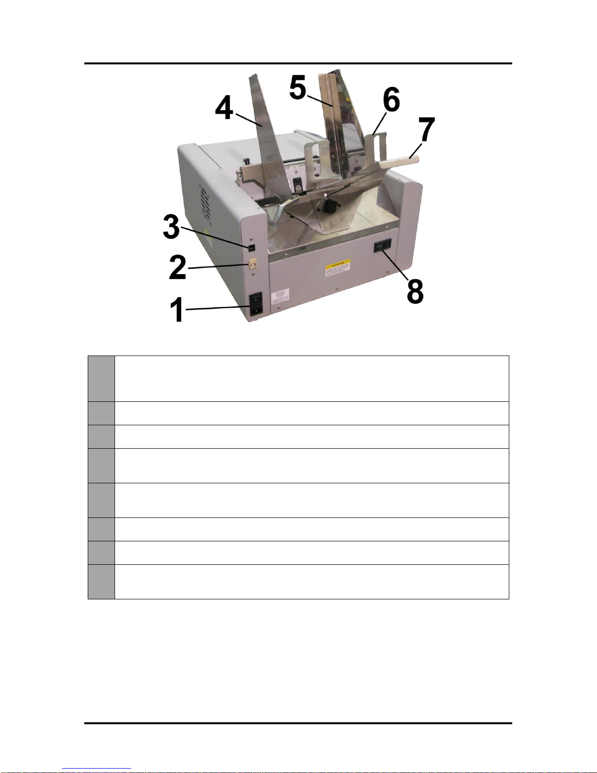
Rear View
1.
Main Power Switch, Receptacle and Fuse –Plug in power cord here. Switch turns
main power ON/OFF. (Use Control Panel LED Power switch to turn off machine for
cleaning and maintenance). Fuse protects the Printer’s electronic circuits.
2.
USB Port Connection –The USB cable attaches to the Printer here.
3.
Network Connection –The network cable plugs in here.
4.
Envelope/Paper Media Guide –All printing is registered against this Guide. It has
adjustable positions for envelopes and paper.
5.
Adjustable Media Guide –Adjusts to hold the paper/media against the Envelope/Paper
Media Guide.
6.
Rear Guide –Holds the paper/media against the Front Plate.
7.
Rear Guide Support –Supports the paper/media.
8.
Counter –LCD displays number of pieces run for a given job. The Reset button zeros
the Counter.

SECTION 1
GETTING ACQUAINTED
3
Print Engine View
1.
Printhead Latch –When closed, connects the Ink Revolver Couplings with the
Printhead Cartridge. When opened, retracts the Ink Couplings from the Printhead
Cartridge and provides access to the Printhead Cartridge for cleaning and replacement.
WARNING! Never attempt to open the Printhead Latch manually, severe damage will
result. Use the Printhead Release button function in the Toolbox utility on your PC or
press the Printhead Latch Release Button (See 4 below).
2.
Ink Revolver Couplings –Connect the ink hoses to the Printhead Cartridge. The
Printhead Latch extends and retracts the couplings from the Printhead.
3.
Printhead Cartridge –Memjet®Printhead produces an 8.5" wide full color print area.
4.
Printhead Latch Release Button –Button inside opening will initiate a Printhead Latch
release cycle. If system is primed, a deprime cycle will run before Latch is released.
Lightly press the button with a non-conductive tool.
5.
Clean Printhead Button –Button inside opening will initiate a “Quick Cleaning”of the
Printhead. Lightly press the button with a non-conductive tool.
6.
Clamshell Latches –Lift both latches at the same time to open the top half of the Print
Engine. DO NOT open while the Printer is operating. DO NOT lift the assembly more
than 60 degrees. DO NOT let the assembly drop, close it gently.

SECTION 1
GETTING ACQUAINTED
4
Ink Tank Door View
1.
Ink Tank Securing Latches –Used to hold the Ink Tanks in the slots.
NOTE: Please be sure that both sides at the bottom part of the latch are engaged.
2.
Ink Tanks –Printer has 5 Ink Tanks: Cyan, Yellow, Magenta, Black, Black
3.
Ink Waste Tray –Catches any waste ink produced by the system. The tray is filled with
absorbent material. Tabs located at the left and right sides of the tray secure the tray to
the print engine frame. Please be sure the tabs click in to secure the tray's position.
4.
Service Station –Cleans the Printhead Cartridge of excess ink and debris, keeps the
Printhead hydrated and protected when not in use, captures ink used to keep nozzles
clear, and acts as a base to support media during printing.
SECTION 1
GETTING ACQUAINTED
5
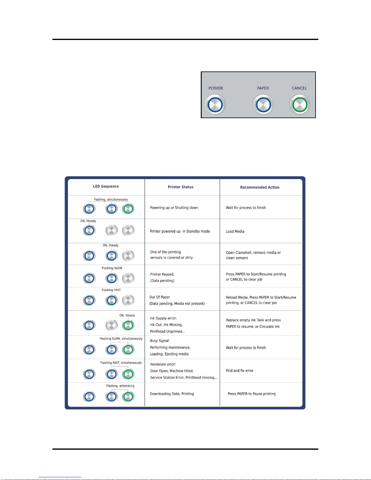
Control Panel Button/LED Indicators
The Control Panel has 3 buttons with LED indicators.
POWER (ON/OFF) –Turns Printer power ON and OFF.
Turn off power for cleaning and maintenance
PAPER (STOP JOB/RESUME) –Stops Paper Feed or
Resumes Printing.
Press to Stop Paper Feed Immediately. Printer
will clear media in Printer and stop.
Press to Resume Printing. Restart printing after a paper feed error (such as a paper jam or
running out of paper).
CANCEL (CANCEL JOB)–Cancels a Job.
Press to Cancel a Job. Once the Printer has stopped, pressing this button clears job from Printer
and Print Queue in Driver. NOTE: Cancelled Jobs must be reloaded before printing can resume.
MORE TROUBLESHOOTING GUIDES on page 54.
FOR A LARGER CHART TO MOUNT ON THE PRINTER, SEE END OF THIS MANUAL.

SECTION 2
INSTALLING THE PRINTER
6
SECTION 2 –Installing the Printer
Contents of Packaging
1.
M1 Printer
2.
Ink Tanks –Cyan, Magenta, Yellow, Black, Black
3.
Printhead Cartridge
4.
Media Side Guides: Registration (Fixed) and Adjustable –
mounting screws attached to Printer
5.
Rear Media Support Guide
–thumbscrew attached to Printer
6.
Media Support Wedges: Narrow and Wide
–mounting hardware attached to Rear Media Support Guide
7.
Envelope Attachment Spacers (pkg. of 2)
8.
AC Power Cord
9.
USB Cable
10.
Operator Manual
11.
Driver Software CD
Before using the Printer the following must be done:
Choose a location for the Printer
Unpack and assemble the Printer
Hydrate the Printhead Cartridge
Remove the Service Station Transport Tab and Shipping Tape
Plug in the Printer and connect it to the computer
Install the Printer Driver
Install the Ink Tanks
Install the Printhead
Set up the feed on the Printer
Choose a Location
The Printer should be placed on a sturdy level worktable or cabinet at least 9 inches from any walls.
Protect the Printer from excessive heat, dust, and moisture. Avoid placing it in direct sunlight.
Unpacking and Setup
Remove the Printer and its parts from the carton. Remove all packing tape. The screws that attach the
various parts of the guides to the Printer are under the tape in their respective positions.

SECTION 2
INSTALLING THE PRINTER
7
Hydrating the Printhead Cartridge
Before you begin assembling the Printer, it is a good idea to hydrate the Printhead Cartridge.
CAUTION
Use electrostatic discharge (ESD) protection when handling.
Hold the Printhead Cartridge by the handles ONLY.
DO NOT touch the ink couplings, nozzle surface or electrical contacts.
DO NOT unpack the Printhead Cartridge until the Printer is ready for
installation. Once unwrapped, delay in installing the Printhead can
compromise print quality due to dehydration.
DO NOT place an unwrapped Printhead on any surface before installing.
Protect the Printhead from scratches, dust, fibers, dirt and other
contaminants at all times.
1. [A] Carefully remove
the Printhead Cartridge
from the foil packaging.
Tear at notch or cut end
with scissors.
[B] Remove the
protective plastic cover.
Hold the Printhead by the
handle and unclip the
cover from the Printhead.
[C] Remove protective
strip from the Printhead
Electrical Contacts.
DO NOT allow removed
strip to touch the
electrical contacts.
[D] Remove protective
strip from the Printhead
Nozzles. Hold the
Printhead by the handle. Pull the strip tab and slowly peel the
strip from the Printhead.
DO NOT pull the strip at less than a 45° angle from the Printhead surface.
DO NOT allow removed strip to touch the Printhead Nozzles.
2. Use distilled water to moisten the foam strip in the orange plastic cover you removed in
Step 1B (or moisten a clean, lint-free cloth). Carefully reinstall the Printhead back into the
plastic cover. Set the Printhead aside for installation later. This rehydrates Printhead and
allows easier priming once it is installed in the Printer.
SECTION 2
INSTALLING THE PRINTER
8
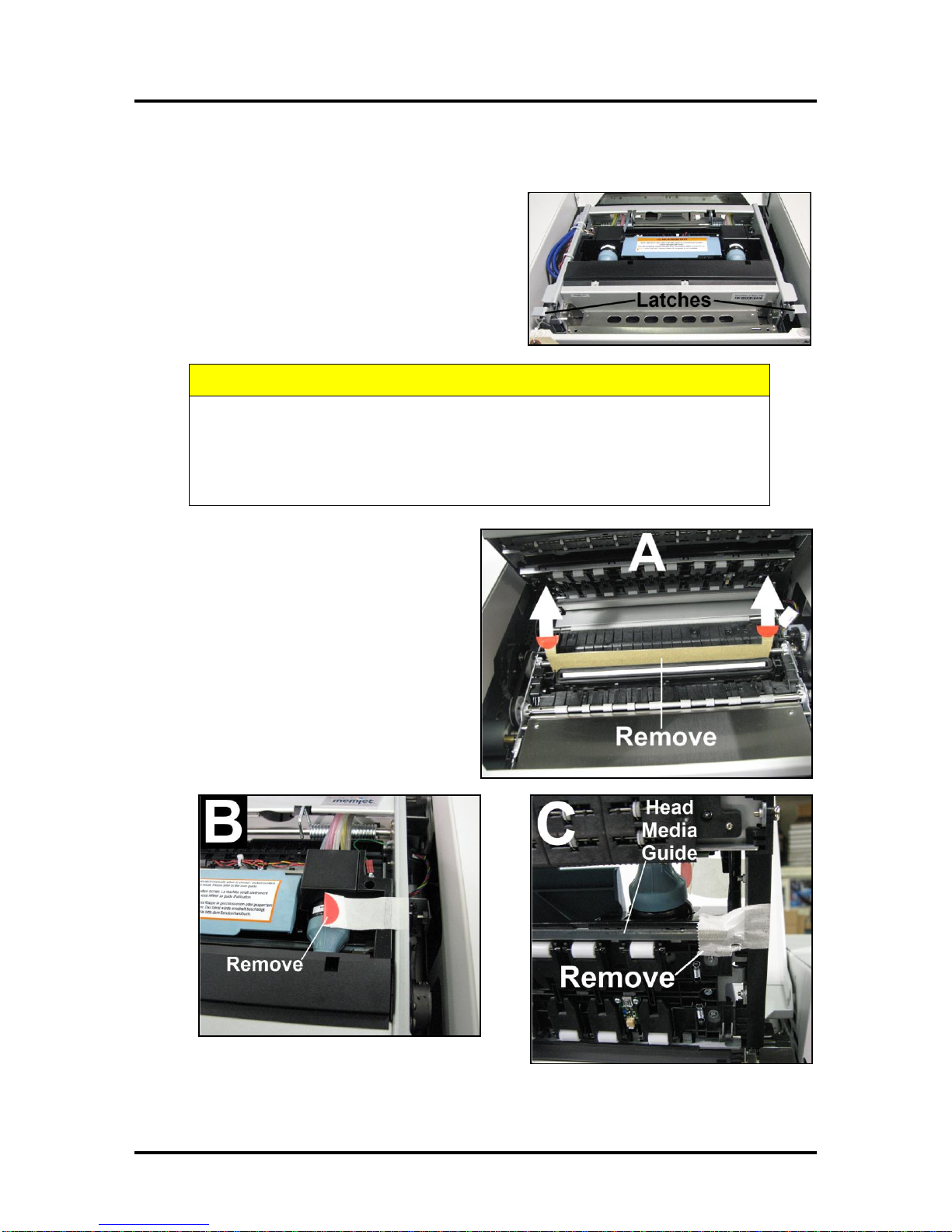
Remove Service Station Transport Tab and Shipping Tape
1. Open the Top Cover.
2. Release the two latches (one on either side of the
Print Engine). Open the top half of the Clamshell by
lifting both levers at the same time.
CAUTION
HOLD ONTO BOTH LATCHES WHEN OPENING AND CLOSING THE PRINT
ENGINE CLAMSHELL TO PREVENT DAMAGE.
DO NOT ALLOW THE CLAMSHELL TO DROP OR SLAM CLOSED.
TO PREVENT DAMAGE TO THE INK LINES, A STOP LIMITS RAISING THE
CLAMSHELL MORE THAN 60°.
3. Remove the cardboard Transport Tab [A]
from the Service Station.
4. Remove the tape [B] securing the Head
Media Guide. (If necessary, wipe off any
tape residue from the Head Media Guide
surface [C].)
5. Carefully close and latch the Upper
Clamshell. Then close the Top Cover.

SECTION 2
INSTALLING THE PRINTER
9
Assembling the Printer
Install the Adjustable Side Guide with two screws [1]:
Next install the Envelope/Paper Side Guide using the two screws [2]
provided.
Attach the Rear Paper Support using the knob [3] provided.
NOTE: The two outside holes fit over the socket head screws.
Install the Rear Guide using the thumbscrew and washer [4]
provided. The washer goes between the screw and the Rear Paper
Support.

SECTION 2
INSTALLING THE PRINTER
10
Connecting the Printer
Plugging in the Printer
Plug the power cord into the receptacle [1] at the rear of the Printer. The internal
power supply in the Printer is rated 115 to 240VAC, 50/60 Hz.
CAUTION
DO NOT USE AN ADAPTER PLUG OR EXTENSION CORD
TO CONNECT THE PRINTER TO THE WALL RECEPTACLE.
DO NOT USE OUTLETS CONTROLLED BY WALL
SWITCHES.
DO NOT USE AN OUTLET THAT SHARES THE SAME
CIRCUIT WITH LARGE ELECTRICAL MACHINES OR
APPLIANCES.
Connecting to the Computer
The Printer connects to the computer through the USB Port [2].
A Network Port [3] is provided when operating in a network environment. See
“Network Connection Setup”in the “Using the Printer Toolbox”section.
Turning Power ON and OFF
Powering Up Printer:
1. Press the Main Power Switch on the Rear Panel.
2. Press the Power Button on the Control Panel.
Powering Down Printer:
CAUTION
WHENEVER POWERING DOWN UNIT, ALWAYS:
1. PRESS THE POWER BUTTON ON THE CONTROL PANEL.
2. WAIT FOR THE PRINTER TO STOP PROCESSING.
3. THEN PRESS THE MAIN POWER SWITCH ON THE REAR PANEL.

SECTION 2
INSTALLING THE PRINTER
11
Install the Printer Driver
For the Printer software to operate properly check that the computer system meets these minimum
requirements:
Windows XP, Windows Vista, Windows 7. (Supports 32 and 64 bit systems)
You must have administrative privileges on the system.
Microsoft Internet Explorer 6.0 or higher.
Java version 6 or higher
USB 2.0 port (ports will be identified as “USB2” or “Enhanced” in the Device Manager.)
Microsoft .NET Framework 3.5 installed (Even if you have a higher version installed,
version 3.5 must also be installed.)
IMPORTANT: Before installing the Printer software (Toolbox and Driver), you should temporarily
disable all antivirus programs and firewalls. In addition, you must be logged onto the system with full
administrative privileges (admin rights).
NOTE: If installing over USB, do not plug in the USB cable until prompted.
1. Check that Printer is plugged in and turned OFF.
Disconnect the USB connection if you have plugged it
in already. Install the disk supplied with the Printer in
your CD drive. When the AutoPlay Window opens,
click “Run Setup.exe”to start.
2. Install Printer Software. Make sure the computer
system meets the minimum requirements and
you have followed the other instructions listed on
the screen. Click “Install Printer Software”.
3. License Agreement. Read the “Software License
Agreement”. If you agree to the terms, check “I
accept…” then click “Next>”.
SECTION 2
INSTALLING THE PRINTER
12
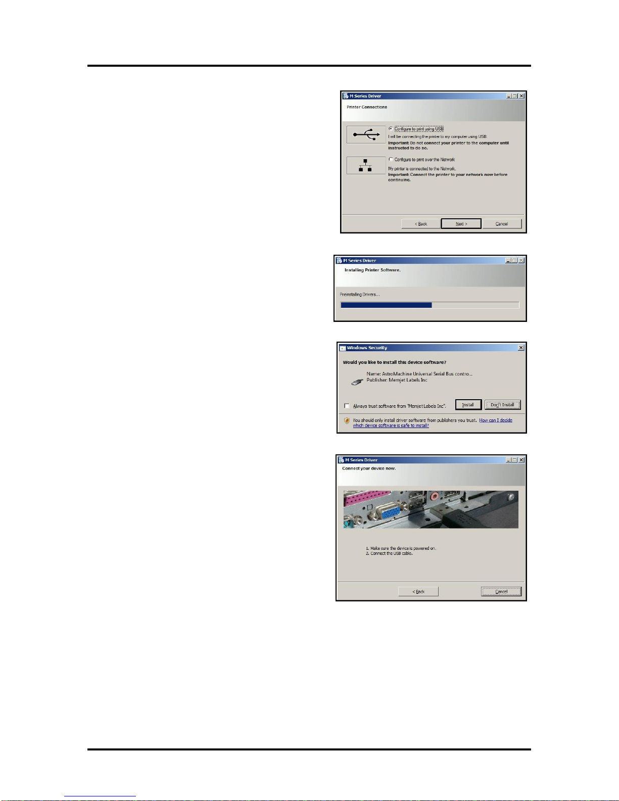
4. Printer Connections. Click “Configure to print
using USB”. Then click “Next>”.
5. Installing Printer Software. Software
download begins.
6. Would You Like to Install This Device
Software? Click “Install”.
7. Connect Device Now. Turn Printer ON and
connect the USB cable. Don’t click on either
button. The software will finish installing.
SECTION 2
INSTALLING THE PRINTER
13
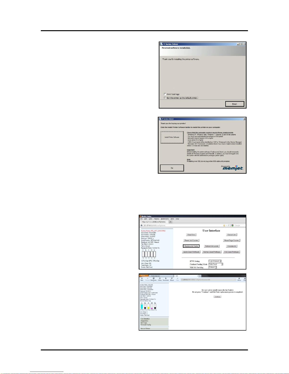
8. Finished software installation. Do not check the
Print Test Page as the Printer is not set up yet.
You can check the “Set this printer as the default
printer”at this time. Click “Next>”.
9. Install Printer Software. Click “Exit”to close
the CD.
10. Restart the computer to complete the installation.
Install the Ink Tanks
The Printer uses one Printhead Cartridge and five Ink Tanks (two Black, one Cyan, one Magenta, and one
Yellow). Install the Ink Tanks as follows:
1. Open the Printer Toolbox. Go to the
Start Menu and open the “Toolbox”.
You will see System Status information
in the upper left corner of the User
Interface window. Note that the
“CKMYK”boxes are empty.
2. Click “Replace Ink Tanks”. This
disconnects Printer communication
with the Ink Tanks and allows safe
installation and replacement. Once the
“Confirm”screen displays, it is safe to
install the Ink Tanks.
IMPORTANT: DO NOT press
“Continue”until after you have
installed the Ink Tank(s) and closed
the Ink Tank Latches.

SECTION 2
INSTALLING THE PRINTER
14
3. Open the Ink Tank Door (hinged at
bottom). Open the three Latches [A].
4. Remove the Ink Tank(s) from packaging.
5. Insert the Ink Tanks (labels up) into their
appropriate color slots [B]. Close the three
Ink Tank Latches.
INSTALLATION TIP: Make sure the
Ink Tanks seat properly. Insert the Ink
Tank into the appropriate Ink Station,
then pull the Ink Tank back about an
inch and push forward firmly to insure
that the Ink Nozzles penetrate the seals
on the Ink Tanks.
6. Click “Continue”on the Confirm
screen, then “Refresh Ink Levels”on
the User Interface screen. The ink
colors fill in as the Ink Tanks are
installed. If the ink colors do not fill in
after a few seconds, click “Replace Ink
Tanks”again and reinstall the Ink
Tank(s).
7. Close the Front Cover.
WARNING!
The ink in the Ink Tanks may be harmful if swallowed. Keep new and used
Tanks out of reach of children. Discard empty tanks immediately.

SECTION 2
INSTALLING THE PRINTER
15
Install the Printhead Cartridge
The Printhead Cartridge is a delicate precision device. Handle with extreme care to avoid damage and
issues that could degrade print quality.
CAUTION
Use electrostatic discharge (ESD) protection when handling.
Hold the Printhead Cartridge by the handles ONLY.
DO NOT touch the ink couplings, nozzle surface or electrical contacts.
DO NOT unpack the Printhead Cartridge until the Printer is ready for
installation. Once unwrapped, delay in installing the Printhead can
compromise print quality due to dehydration.
DO NOT place an unwrapped Printhead on any surface before installing.
Protect the Printhead from scratches, dust, fibers, dirt and other
contaminants at all times.
1. With the Printer power ON, open the Top
Cover. Press the Printhead Latch Release
Button [1]. The Printer will run a routine, then
the Latch will pop open [2].
NOTE: Remove the Cap Protectors on the
Ink Nozzles [3]. Be sure to open the Latch
fully to retract the Ink Nozzles.
CAUTION
DO NOT PRY OR MANUALLY LIFT THE PRINTHEAD LATCH OR THE
LATCH MAY BREAK. ONLY OPEN THE LATCH USING THE RELEASE
BUTTON ON THE PRINTER OR THE PRINTHEAD RELEASE COMMAND
IN THE PRINTER TOOLBOX.

SECTION 2
INSTALLING THE PRINTER
16
2. Take the Printhead
Cartridge you hydrated
and set aside earlier,
remove the orange cover
and proceed to Step 3.
Otherwise, follow the
Steps below:
[A] Carefully remove the
Printhead Cartridge
from the foil packaging.
Tear at notch or cut end
with scissors.
[B] Remove the protective
plastic cover. Hold the
Printhead by the handle and
unclip the cover from the
Printhead.
[C] Remove protective
strip from the Printhead
Electrical Contacts.
DO NOT allow removed strip to touch the electrical contacts.
[D] Remove protective strip from the Printhead Nozzles. Hold the Printhead by the handle.
Pull the strip tab and slowly peel the strip from the Printhead.
DO NOT pull the strip at less than a 45° angle from the Printhead surface.
DO NOT allow removed strip to touch the Printhead Nozzles.
IMPORTANT! Use distilled water to moisten the foam strip in the orange plastic cover you
removed in Step 2B (or moisten a clean, lint-free cloth). Carefully snap the Printhead back
into the plastic cover. Set the Printhead aside for 15 to 20 minutes. This rehydrates Printhead
and allows easier priming once it is installed in the Printer.
WARNING!
TO AVOID ELECTRICAL SHOCK OR SHORTING:
Before installing Printhead, make sure nozzles are hydrated and contacts are DRY!
3. Carefully insert the Cartridge into the compartment at an angle [4], with the Printhead surface
facing down and the Ink Nozzles facing the Ink Hoses. Once it is seated, gently tilt the Cartridge
back until it snaps into an upright position [5]. DO NOT FORCE the Cartridge into position.
Other manuals for AstroJet M1
2
Table of contents
Other Memjet Printer manuals

Memjet
Memjet SFP User manual

Memjet
Memjet AstroJet M1 User manual

Memjet
Memjet MACH 8 User manual

Memjet
Memjet VIP Color VP5 Series User manual

Memjet
Memjet AstroJet M1 User manual

Memjet
Memjet Printware iJetColor Press Service manual

Memjet
Memjet icube 1-3 Owner's manual

Memjet
Memjet AS-1180C User manual

Memjet
Memjet MACH 5 User manual

Memjet
Memjet Quadient Rena MACH 6 User manual


