Memjet AS-1180C User manual

MACH 8(AS-1180C)
Digital Color Document Printer
User Guide

SAFETY PRECAUTIONS
THIS EQUIPMENT PRESENTS NO PROBLEM WHEN USED PROPERLY.
HOWEVER, CERTAIN SAFETY RULES SHOULD BE OBSERVED WHEN
OPERATING THE MACH 8 PRINTER.
BEFORE USING THE PRINTER, YOU SHOULD READ THIS MANUAL
CAREFULLY AND FOLLOW THE RECOMMENDED PROCEDURES, SAFETY
WARNINGS, AND INSTRUCTIONS:
Keep hands, hair, and clothing clear of rollers and other moving parts.
DO NOT place hands/feet or other body parts under the Feed Table or Receiving Tray.
Avoid touching moving parts or materials while the machine is in use. Before clearing a jam,
be sure machine mechanisms come to a stop.
Always turn off the machine before making adjustments, cleaning the machine, or performing
any maintenance covered in this manual.
The power cord, supplied with the machine, should be plugged into a properly grounded,
easily accessible wall outlet near the machine. Failure to properly ground the machine can
result in severe personal injury and/or fire.
The power cord and wall plug is the primary means of disconnecting the machine from the
power supply.
DO NOT use an adapter plug on the power cord or wall outlet.
DO NOT remove the ground pin from the power cord.
Do NOT use extension cords.
DO NOT route the power cord over sharp edges or trap it between furniture.
Avoid using wall outlets that are controlled by wall switches or shared with other equipment.
Make sure there is no strain on the power cord caused by jamming it between equipment,
walls or furniture.
DO NOT remove covers. Covers enclose hazardous parts that should only be accessed by a
qualified service representative. Report any cover damage to your service representative.
This machine requires periodic maintenance. Contact your authorized service representative
for required service schedules.
To prevent overheating, do not cover the vent openings.
Use this equipment only for its intended purpose.
In addition, follow any specific occupational safety and health standards for your workplace or area.
This manual is intended solely for the use and information of Neopost, its designated agents,
customers, and their employees. The information in this guide was obtained from several different
sources that are deemed reliable by all industry standards. To the best of our knowledge, that
information is accurate in all respects. However, neither Neopost, Inc. nor any of its agents or
employees shall be responsible for any inaccuracies contained herein.
Memjet®is a registered trademark.
All other trademarks are the property of their respective holders.
All rights reserved. No part of this book may be reproduced or transmitted in any form or by any means, electronic or mechanical,
including photocopying, recording, or any information storage and retrieval system, without permission in writing from the publisher

TABLE OF CONTENTS
i
Table of Contents
SECTION 1 – GETTING ACQUAINTED .............................................................................1
FRONT VIEW .................................................................................................................................................. 1
REAR VIEW .................................................................................................................................................... 2
PRINT ENGINE VIEW ........................................................................................................................................ 3
INK TANK VIEW............................................................................................................................................... 4
HIGH CAPACITY OUTPUT STACKER (OPTIONAL)...................................................................................................... 5
SECTION 2 – INSTALLING THE PRINTER..........................................................................6
TRANSPORT INSPECTION ................................................................................................................................... 6
TOOLS NEEDED ............................................................................................................................................... 6
CHOOSING THE LOCATION ................................................................................................................................. 6
Printer (Print Engine) Must be Level.................................................................................................................... 6
OPERATING CONDITIONS .................................................................................................................................. 7
UNPACKING.................................................................................................................................................... 7
Contents of Packaging............................................................................................................................ 7
REMOVING THE CARDBOARD SHIPPING INSERT AND SHIPPING TAPE .......................................................................... 8
LEVELING THE PRINTER (PRINT ENGINE)............................................................................................................... 9
Checking the Tilt Readings.................................................................................................................... 10
CONNECTING THE PRINTER .............................................................................................................................. 11
Plugging in the Printer .......................................................................................................................... 11
Powering the Printer ON and OFF ........................................................................................................ 11
Powering-Up the Printer:................................................................................................................................... 11
Powering-Down the Printer:.............................................................................................................................. 11
Connecting to the Computer................................................................................................................. 12
Minimum Computer System Requirements ...................................................................................................... 12
INSTALLING THE PRINTER SOFTWARE (DRIVER &TOOLBOX)................................................................................... 13
Connecting the Printer via Network (Ethernet Port)............................................................................. 16
INSTALLING THE INK TANKS.............................................................................................................................. 18
Ink Tank Anatomy................................................................................................................................. 18
Procedure (Installing the Ink Tanks): .................................................................................................... 19
INSTALLING THE PRINTHEAD CARTRIDGE ............................................................................................................ 22
Protective Packaging ............................................................................................................................ 22
Procedure (Installing the Printhead Cartridge)..................................................................................... 24
INSTALLING/REMOVING THE HEAD MEDIA GUIDE................................................................................................ 28
SECTION 3 –INSTALLING THE OUTPUT STACKER (OPTIONAL) ......................................30
UNPACKING.................................................................................................................................................. 30
Contents of Packaging.......................................................................................................................... 30
CONNECTING/ALIGNING THE OUTPUT STACKER................................................................................................... 30
SECTION 4 – OPERATING THE PRINTER .......................................................................31
MACH 8CONTROL PANEL FUNCTIONS ............................................................................................................. 31
For The Print Engine:............................................................................................................................ 31
Print Engine Status Light (LED) Indicators.......................................................................................................... 32
For the Feed Table: ............................................................................................................................... 35
Feed Table: Status Light (LED) Indicators........................................................................................................... 35
SETTING UP THE FEED..................................................................................................................................... 36
PRINTER DRIVER PROPERTIES........................................................................................................................... 40

TABLE OF CONTENTS
ii
General Tab ....................................................................................................................................................... 40
Layout Tab ......................................................................................................................................................... 43
Color Tab............................................................................................................................................................ 44
Import/Export Tab ............................................................................................................................................. 46
Services Tab ....................................................................................................................................................... 46
TOOLBOX FEATURES....................................................................................................................................... 47
User Interface Menu............................................................................................................................. 47
Diagnostics Menu ................................................................................................................................. 52
Ink Usage Menu.................................................................................................................................... 53
System Settings..................................................................................................................................... 55
Service Menu ........................................................................................................................................ 57
PRINTING..................................................................................................................................................... 58
Printhead Cartridge Conditioning......................................................................................................... 58
SECTION 5 – SOFTWARE SETUP INFORMATION...........................................................59
GENERAL SOFTWARE SETUP INFO ..................................................................................................................... 59
ADOBE®ACROBAT/READER SETUP TIPS ............................................................................................................. 60
SETTING UP A JOB IN MICROSOFT WORD®(2007) .............................................................................................. 61
Letter (8.5” x 11):............................................................................................................................................... 61
SECTION 6 – OPERATING THE STACKER (OPTIONAL) ...................................................63
OUTPUT STACKER CONTROL PANEL BUTTONS ..................................................................................................... 63
Output Stacker Status Light (LED) Indicators........................................................................................ 64
OUTPUT STACKER SETUP................................................................................................................................. 65
SECTION 7 – OPERATOR MAINTENANCE .....................................................................66
REPLACING THE INK TANKS .............................................................................................................................. 66
Cleaning Ink Tank Contacts & Prism ..................................................................................................... 66
Ink Tank Storage & Shelf Life ................................................................................................................ 67
Ink Tank Service Life.............................................................................................................................. 67
Ink Tank Disposal.................................................................................................................................. 68
CLEANING THE PRINTHEAD CARTRIDGE .............................................................................................................. 68
From the M Series Driver: ..................................................................................................................... 68
From the Toolbox:................................................................................................................................. 68
Manual Printhead Cleaning:................................................................................................................. 69
REPLACING THE PRINTHEAD CARTRIDGE............................................................................................................. 70
Printhead Storage & Shelf Life.............................................................................................................. 71
Printhead Service Life ........................................................................................................................... 71
Printhead Disposal................................................................................................................................ 71
INSPECTING &CLEANING THE LIP OF THE CAPPING STATION .................................................................................. 72
INSPECTING THE WIPER ROLLER ....................................................................................................................... 73
CLEANING/REPLACING SERVICE STATION ITEMS .................................................................................................. 74
Removing the Service Station ............................................................................................................... 74
Cleaning the Service Station ................................................................................................................. 76
Wiper Roller Removal and Cleaning or Replacement........................................................................................ 76
Wiper Motor Assembly Removal and Cleaning ................................................................................................. 77
Printing Platen and Capping Station Removal and Cleaning.............................................................................. 78
Cleaning the Service Station Tray ...................................................................................................................... 78
Suggestion for High Volume Users: ................................................................................................................... 78
Installing the Service Station ................................................................................................................ 79
Still Experiencing Print Quality Issues? ................................................................................................. 82
INSPECTING/REPLACING THE WASTE INK TRAY .................................................................................................... 83
REPLACING THE SHEET SEPARATORS .................................................................................................................. 84

TABLE OF CONTENTS
iii
JAMS IN THE PRINTER ..................................................................................................................................... 85
Removing Jammed Media .................................................................................................................... 85
CLEANING THE PRINTER BODY.......................................................................................................................... 87
CLEANING THE FEED ROLLERS AND FORWARDING ROLLERS .................................................................................... 87
CLEANING THE FEED SENSOR ........................................................................................................................... 88
CLEANING OTHER ITEMS INSIDE THE PRINT ENGINE .............................................................................................. 89
Grit Rollers (Media Transport Rollers) .................................................................................................. 89
Media (Paperpath) Sensors .................................................................................................................. 89
Capping Station Lip............................................................................................................................... 89
Paperpath Surfaces............................................................................................................................... 89
Printing Platen Surface ......................................................................................................................... 89
Cleaning the Ink Revolver Couplings..................................................................................................... 91
PRINTER MAINTENANCE SCHEDULE ......................................................................................................... 92
PREPARING PRINTER FOR TRANSPORT................................................................................................................ 93
Local relocation .................................................................................................................................... 93
Remote relocation or shipping.............................................................................................................. 93
SECTION 8 – TROUBLESHOOTING GUIDE .....................................................................96
PRINT QUALITY ISSUES: .................................................................................................................................. 96
Examples of Print Quality Issues (including possible causes and solutions) ......................................... 97
Air in Printhead Nozzle Area:............................................................................................................................. 97
Clogged/Damaged/Dead Nozzles: ..................................................................................................................... 98
Color Mixing Issues: ........................................................................................................................................... 99
Scuff Marks and Smudging Issues:................................................................................................................... 100
Fuzzy/Distorted Print ....................................................................................................................................... 102
THE INK TANK(S)......................................................................................................................................... 103
THE PRINTHEAD CARTRIDGE .......................................................................................................................... 104
THE PRINTER .............................................................................................................................................. 106
Dots or Lines Printed on Media........................................................................................................... 106
Power Problems.................................................................................................................................. 106
Service Station Problems .................................................................................................................... 107
Interface Communication Problems ................................................................................................... 108
Feeding Problems ............................................................................................................................... 109
ERRORS AND WARNINGS .............................................................................................................................. 110
Printer Alert Window Messages ......................................................................................................... 110
Toolbox System Status Messages ....................................................................................................... 111
APPENDIX A – SPECIFICATIONS .................................................................................115
MACH 8 Specifications........................................................................................................................ 115
Optional High Capacity Output Stacker Specifications....................................................................... 115
APPENDIX B – SUPPLIES AND OPTIONAL HARDWARE ...............................................116
OBTAINING SUPPLIES,SERVICE AND SUPPORT ................................................................................................... 116
APPENDIX C – QUICK REFERENCE INFO .....................................................................117
PRINTER CONTROL PANEL LED SEQUENCES ...................................................................................................... 117

TABLE OF CONTENTS
iv
NOTES
______________________________________________________
______________________________________________________
______________________________________________________
______________________________________________________
______________________________________________________
______________________________________________________
______________________________________________________
______________________________________________________
______________________________________________________
______________________________________________________
______________________________________________________
______________________________________________________
______________________________________________________
______________________________________________________
SECTION 1
GETTING ACQUAINTED
1
SECTION 1 – Getting Acquainted
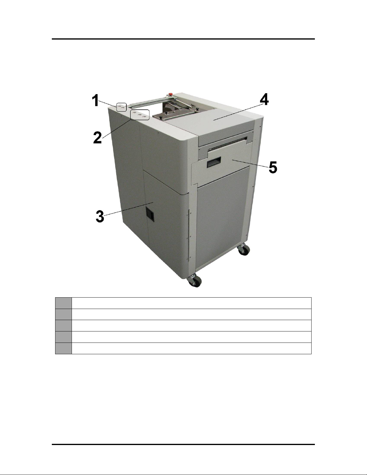
Front View
1.
Feed Table Controls – Raise and lower Feed Table for loading media.
2.
Print Engine Controls On/Off, Paper/Resume and Pause/Cancel Buttons.
3.
Storage Compartment – Holds media, ink and other supplies.
4.
Top Cover – Provides access to the Print Engine.
5.
Ink Tank Door – Provides access to the Ink Tanks and Service Station.
SECTION 1
GETTING ACQUAINTED
2
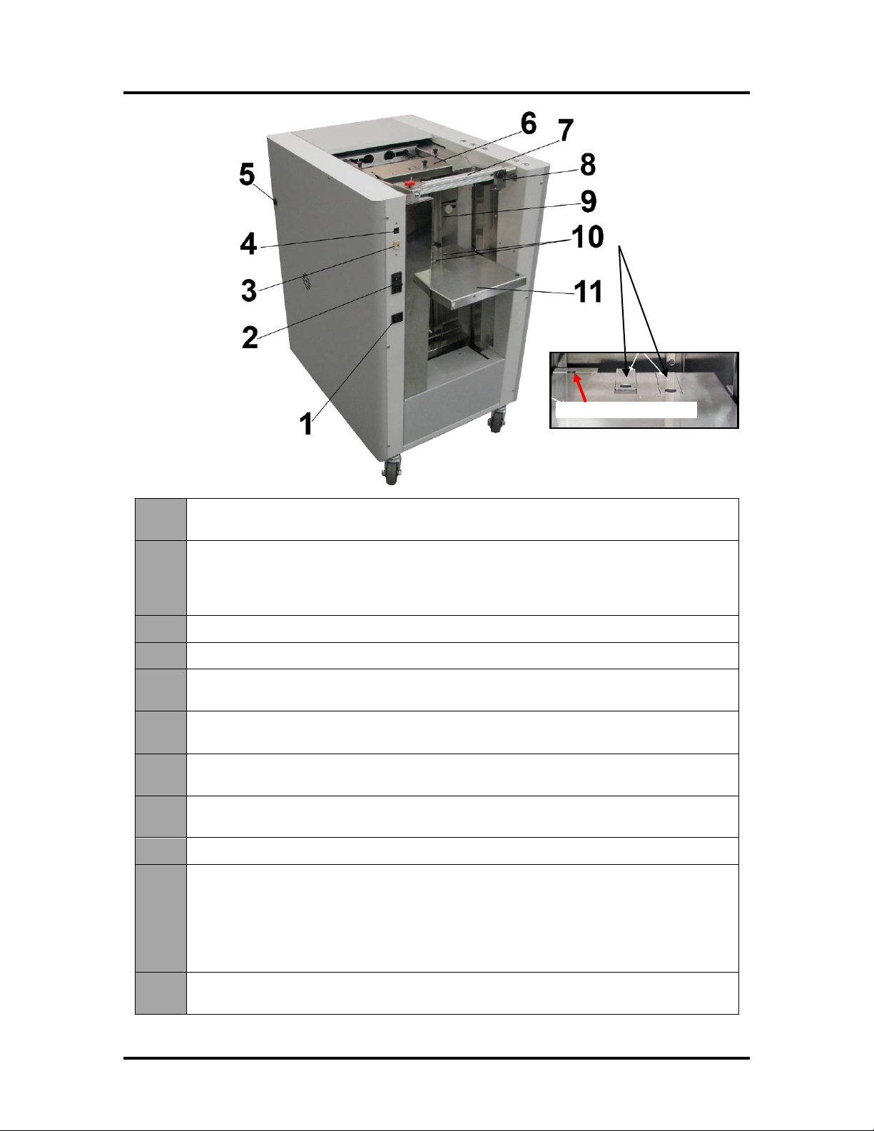
Rear View
1. Output Stacker Power Out –Connect power cord from optional High Capacity
Output Stacker here. Outlet is rated for 1A, 115VAC.
2. Main Power Switch, Receptacle and Fuse–Plug in power cord here. Switch turns
main power ON/OFF. Fuse (2.5A, 250V, slow blow) provides over-current protection.
(IMPORTANT: Use Control Panel ON/OFF button to power-down Print Engine
before turning off main power.)
3.
USB Port Connection –The USB cable, from the computer, attaches here.
4.
Network Connection – The network cable plugs in here.
5. Stacker Interface Port –Stacker Interface Cable for the optional, Automatic High
Capacity Output Stacker connects here.
6. Feed Rollers and Sheet Separators – Feeds and separates media; delivering one
piece at a time into the printing area.
7. Skew Control Bridge –Adjust so the Skew Control Guide can be positioned near
the trailing edge of the media.
8. Skew Control Guide–Adjust to the width of the media; to keep the media stack
square and control skew.
9.
Right Media Side Guide – Adjustable to fit different widths of media.
10.
Feed Table Extensions – Slide forward/back, using finger-hole, to support different
media widths. Slide one or both forward to support wider media. Slide one or both
back to support narrower media.
Tip: If Right Media Side Guide won’t move past a certain point; check to be sure the
Feed Table Extensions and Separator Lockdown/Release Tabs, aren’t interfering
with the guide.
11. Feed Table –Load up to 5,000 sheets (10 reams). Raises and lowers with load.
Media feeds from top of stack. Feed Table Sensor detects presence of media.
Feed Table Sensor

SECTION 1
GETTING ACQUAINTED
3
Print Engine View
1. Ink Revolver Couplings – Connect the ink hoses to the Printhead Cartridge. The
Printhead Latch extends and retracts the couplings from the Printhead.
2.
Printhead Latch – When closed; the Ink Revolver Couplings extend/connect with the
Printhead Cartridge. When opened; the Ink Revolver Couplings retract/disconnect from
the Printhead Cartridge, providing access for Printhead Cartridge
installation/removal/replacement. (See #3 below).
WARNING! Never attempt to open the Printhead Latch manually, severe damage will
result. Use the Printhead Release button function in the Toolbox utility on your PC.
3.
Printhead Latch Release Button* – Initiates a Printhead Latch release cycle. If system
is primed with ink; a “System Deprime” cycle will occur before the Printhead Latch is
released. Lightly press the button with a non-conductive tool.
*Similar function can be accessed through the Printer Toolbox User Interface screen on your
computer. If you are replacing the printhead; it is best to use the “Release Printhead” button from the
Toolbox utility.
4.
Printhead Cartridge – MemjetTM Printhead. Produces an 8.5" wide full color print area.
5. Print Ink Channels Button* –Prints 5 bars (1 bar from each ink tank) to indicate how
well the Printhead Nozzles are working. Press the button with a non-conductive tool.
*Same function can be accessed through the Printer Toolbox Diagnostics screen on your computer.
6.
Clamshell Latches – Lift both latches at the same time to release and swing open the
“clamshell” (top section of the Print Engine).
Do NOT open while the Printer is operating.
Do NOT let the Clamshell drop. Close it gently and then release the latches slowly.
Make Sure the Clamshell is closed and locked before operating.

SECTION 1
GETTING ACQUAINTED
4
Ink Tank View
(Behind the Ink Tank Door)
1.
Ink Tank Securing Latches –Used to hold the Ink Tanks securely into the slots and
against the electrical contacts within the print engine.
CAUTION! Before removing/installing Ink Tanks; please be sure to power-down the
Print Engine or press the “Replace Ink Tanks” button, in the Toolbox. If this rule is not
followed damage to the Ink Tanks may result, rendering them unusable.
NOTE: Please be sure that both sides, at the bottom part of the latch, are engaged.
2. Ink Tanks – Five Ink Tanks are used in the printer.
Cyan (C), Yellow (Y), Magenta (M), Black (K), Black (K)
3.
Waste Ink Tray – The purpose of this tray is to catch the waste ink produced by the
system. This tray is filled with absorbent material. This tray must be replaced when it
becomes saturated. Please inspect routinely. The tabs located at the left and right sides
of the tray secure the tray to the print engine frame. Please be sure the tabs “click” into
the frame, to secure the tray's position.
4.
Service Station – Contains four major components.
- Wiper Roller Assembly - cleans the Printhead Cartridge of excess ink and debris.
- Capping Station - keeps the Printhead capped, hydrated and protected when not in
use.
- Printing Platen - provides the base to support media during feeding and printing.
- Tray – holds all of the above components and captures the waste ink. The waste ink
eventual makes its way from the Service Station Tray into the Waste Ink Tray.
Please refer to the “Operator Maintenance” section for information on how to properly
maintain the Service Station and its components.
4
2
1
3
SECTION 1
GETTING ACQUAINTED
5
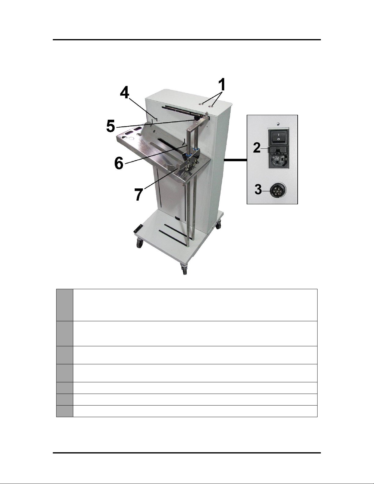
High Capacity Output Stacker (optional)
1. Control Panel –UP button raises Receiving Tray. DOWN button lowers Receiving
Tray. Pressing the same button a second time; stops the Tray at its current location.
Pressing both buttons simultaneously, for about 6 seconds, repositions the Tray to the
“ready”position.
2. Main Power Switch, Receptacle and Fuse –Plug in power cord here. Switch turns
main power ON/OFF. Fuse (2.5A, 250V, slow blow) provides over-current protection.
CAUTION: Disconnect power cord from Stacker before checking/replacing fuse.
3. Interface Port– Stacker Interface Cable, from the MACH 8 Printer to the Output
Stacker, plugs in here.
4. Stack Height Sensor–Senses the top of the paper stack, in Tray, and automatically
positions (raises or lowers) Tray as needed.
5.
Backstop Adjustment Knob – Locks and unlocks the Backstop for positioning.
6.
Backstop – Adjusts to accommodate media lengths from 5" to 13" long.
7.
Media Side Guide – Adjusts to accommodate media widths from 6.5” to 9" wide.

SECTION 2
INSTALLING THE PRINTER
6
SECTION 2 – Installing the Printer
Before using the MACH 8 Printer the following must be done:
•Transport Inspection. Upon delivery; inspect packaging and report any issues to the Carrier
•Gather Tools
•Choose a location for the Printer
•Unpack and Verify Contents.
•Remove the Service Station Transport Tab & Shipping Tape
•Position and Level the Printer (Print Engine)
•Plug in the Printer
•Install the Printer Software (Driver & Toolbox). Then Connect Printer to Computer
•Install the Ink Tanks
•Install the Printhead
•Verify that the Head Media Guide is properly installed
•Setup the Feed System to accommodate your media
Transport Inspection
The printer is shipped in appropriate packaging so that, under normal shipping conditions, it reaches its
destination without damage.
NOTICE: Report damage to the carrier. The carrier is liable for any damage during transport.
Transport and storage should take place under the following conditions:
- At temperatures between -25°C and +50°C (-13 °F to 122 °F).
- At a relative air humidity between 5% and 95%, non-condensing.
- At an atmospheric pressure between 70 kPa and 105 kPa.
Exposure to conditions that are not permissible may lead to damage which is not externally visible.
IMPORTANT Please save the packaging materials for future use! It will be required if you ever need to
ship the printer. Before shipping; please refer to the section titled “Preparing the Printer for Transport”.
Tools Needed
•Knife and scissors to open packaging
•Carpenters Level (9” or smaller)
•Protective, nitrile powder-free gloves should be worn to avoid getting ink on hands when
removing protective packaging materials from the ink coupling areas, the Ink Tank areas, and
when installing/removing Printhead Cartridge and Ink Tanks.
•Distilled or de-ionized water
•Non-abrasive, lint free cloths
Choosing the Location
The Printer should be placed on a sturdy/level floor surface and it should be positioned at least 9 inches
from any walls. Protect the Printer from excessive heat, dust, and moisture – avoid placing it in direct
sunlight.
Printer (Print Engine) Must be Level: Please refer to “Leveling the Printer (Print Engine)”, below, for
details on why this is important and how to do this.
SECTION 2
INSTALLING THE PRINTER
7
Operating Conditions
Operation should take place under the following conditions:
- At temperatures between +15°C and +35°C (59 °F to 95 °F).
- At a relative air humidity between 20% and 80%, non-condensing.
- At an atmospheric pressure between 70 kPa and 105 kPa.
- Printer and Print Engine should be protected from excessive environmental debris/dust.
- Printer must be placed on a sturdy floor surface.
- Printer (Printer Engine) must be leveled, using adjustable casters, front to back and left to right.
Exposure to conditions that are not permissible may lead to damage which is not externally visible.
Allow the printer, printhead and ink tanks to acclimate to ambient temperature before using the printer.
Unpacking
Two or more people are required to lift the printer from its packaging.
Remove the Printer and its parts from the carton. Remove all packing tape.
Save the packaging in a safe place, for possible future use.
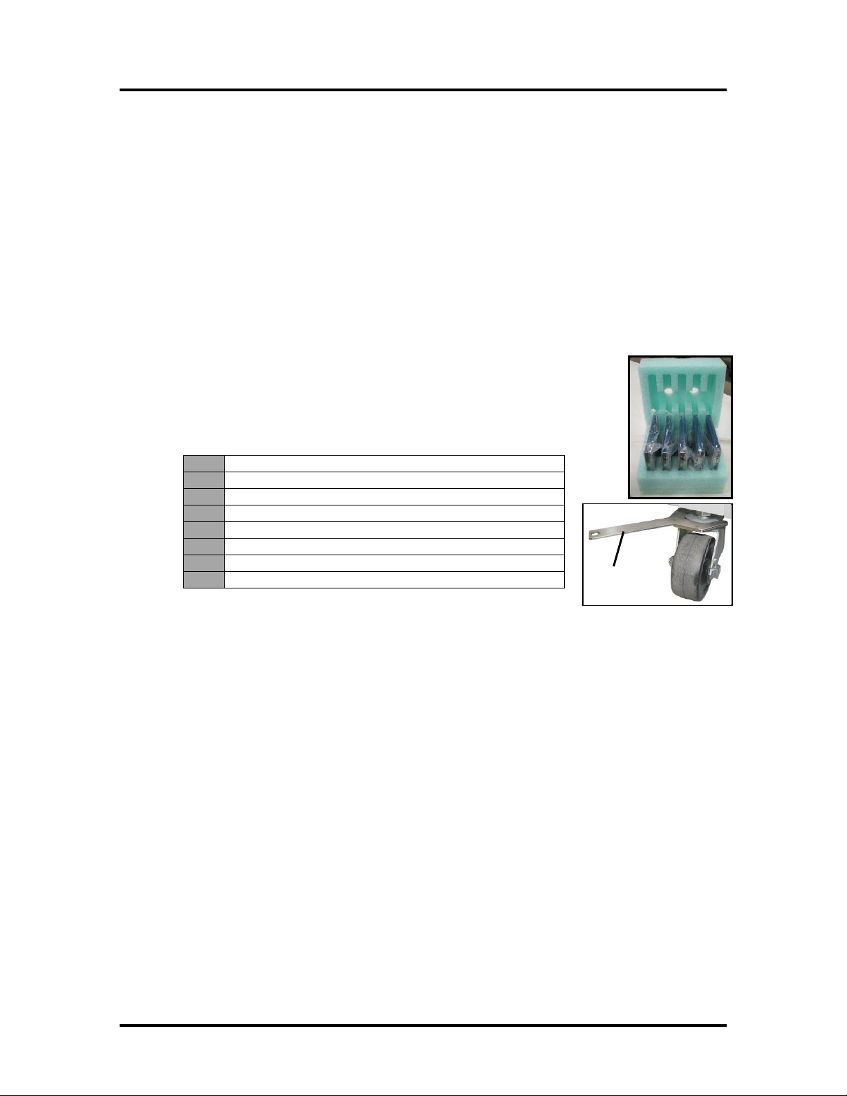
Contents of Packaging
NOTE: Items are shipped inside the Storage Compartment of the Printer.
The following items are included with your printer:
1.
MACH 8 High Capacity Printer
2.
Ink Tanks – Cyan, Magenta, Yellow, Black, Black
3.
Printhead Cartridge
4.
AC Power Cord
5.
USB Cable
6.
Operator Manual
7.
Driver Software CD
8.
Caster Adjusting Wrench
Note: Ink Tanks and Printhead Cartridges can be purchased through your Dealer/Distributor.
See “Appendix B” for supplies information.
wrench

SECTION 2
INSTALLING THE PRINTER
8
Removing the cardboard Shipping Insert and Shipping Tape
WARNING! To avoid possible damage to the printer; do NOT plug-in, or power-up, the printer
until all shipping materials have been removed; as described below.
1. Open the Top Cover.
2. Carefully release both latches (one on either side of
the Print Engine), and lift up with both hands, to
gently swing open the Print Engine Clamshell.
CAUTION
TO PREVENT DAMAGE; HOLD ONTO (RELEASE) BOTH
LATCHES WHEN OPENING AND CLOSING THE CLAMSHELL.
DO NOT FORCE/SLAM THE CLAMSHELL CLOSED.
AFTER CARFULLY CLOSING THE CLAMSHELL, GENTLY
RELEASE BOTH LATCHES.
3. Remove the cardboard “Shipping Insert”
[A], by pulling up on both red tabs at the
same time. The “Shipping Insert” secures the
Service Station during printer transport.
4. Remove the Tape [B]. The tape wraps
around the underside of the Clamshell to
secure the Head Media Guide. (If necessary,
wipe off any tape residue from the Head
Media Guide surface [C].)
5. Gently close and latch the Clamshell.
6. Close the Top Cover.

SECTION 2
INSTALLING THE PRINTER
9
Leveling the Printer (Print Engine)
IMPORTANT! It is critical that the Printer Engine is level front-to-back and left-to-right.
Why is this Important?
The printer’s ink delivery systems, and waste ink drainage system, depend on the Print Engine being
level to perform properly. If this rule is not followed you will experience print quality issues and ink
waste draining issues that could cause damage to the printer.
- Try to insure that the floor surface you are going to place the Printer on is sturdy, flat and level.
- If the floor surface is not sturdy, flat and level then the printer should not be placed on it.
- Do NOT use the Toolbox utilities “Tilt” readings to level the Print Engine.
- Use an accurate level (i.e. bubble level), to check that the Print Engine is level (front to back and
left to right). It is not acceptable to use your “cell phone app” to check level.
- Do NOT place shims/blocks under the Casters or frame.
- If the Print Engine cannot be leveled at the current location, then the printer should be moved to a
different location (floor surface) where it can be leveled.
- Do NOT move the printer while the power is ON.
- If you move the printer, please be sure to re-check that it is level before powering it on.
Use the following procedure to check and level the Print Engine.
1. Open the Top Cover.
2. Left to Right:Check the Bubble Gauge on the front
bridge of the Print Engine. NOTE: If no Bubble Gauge is
mounted, place a small level (9" or smaller) across the
front bridge of the Print Engine as shown [A]. (If level
does not fit on front bridge, you can place the level on the
rear bridge frame on the Print Engine.)
Adjust the casters as necessary to level the Print Engine.
(See Step 4)
NOTE: Level must be placed on the Print Engine or
Print Engine frame (not on Printer Cabinet) to get an
accurate reading.
3. Front to Back: Place the level on the Print Engine Side
Frame [B].
Adjust the casters as necessary to level the Print Engine
(See Step 4).
NOTE: You may have to repeat Steps 2 & 3 to level the
Print Engine in both directions.
4. Adjusting Casters. Use the wrench (included) to loosen
the large nut on top of the caster [C]. Adjust the caster to
the desired height, then tighten the nut so it snugs-up
against the bottom of the Printer to lock the Caster in
place. Then recheck level.
SECTION 2
INSTALLING THE PRINTER
10
Checking the Tilt Readings
Once you have the Printer Driver installed, and the Print Engine has been powered-up for at least 15
minutes; you should return to this procedure to check the “Tilt” readings.
WARNING: You should NOT use the Toolbox utilities “Tilt” readings to level the Print Engine. However
once you are sure the Print Engine has been properly leveled, as described on the previous page, it is
important to routinely monitor the “Tilt” readings.
NOTE: When the Print Engine electronics are cold; the Tilt readings may not be accurate. You may see
them fluctuate/change as the electronics warm-up. Please allow the Print Engine to remain powered-up for
at least 15 minutes before checking/adjusting.
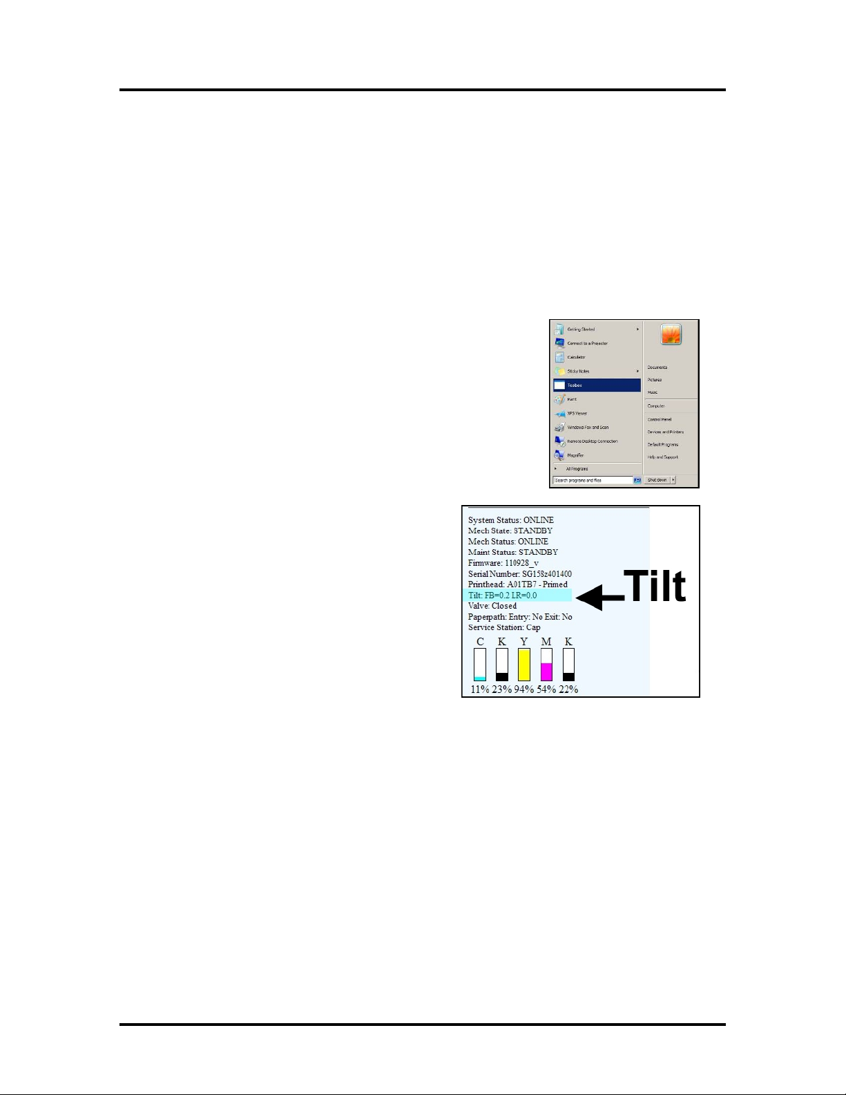
1. Go to the Start Menu, All Programs, Memjet, M Series Driver,
then open the “Toolbox”.
2. When the Toolbox opens; on the User Interface screen, find
“Tilt”, in the status information along the left side.
You will see readings for Front-to-Back (FB) and Left-to-Right
(LR).
These readings should be “0” or very close to zero.
NOTE: The FB and LR orientations are in reference to the print
engine, not the operator.
a. If the Tilt readings are (– 0.9 to 0.9) they will be shown in
black; indicating that the Print Engine is
nearly level (within normal tolerances).
b. If the Tilt readings reach -1.9 or 1.9 they
will be shown in purple. This is a
warning that the print engine is slightly
out of level (out of normal tolerances).
Please recheck the level of the Print
Engine.
c. If the Tilt readings reach -2.0 or 2.0 they
may be shown in red*; indicating that
the Print Engine is too far out of level.
Please stop using the printer and recheck
the level of the Print Engine.
NOTE: If you are sure the Print Engine is level, but the Tilt readings are still shown in purple or
red*; contact service support to have them verify level and possibly recalibrate the Tilt sensor.
* Character color may not change to red with some firmware versions. In this case monitor the
actual tilt reading. If it reaches -2.0 (or lower) or 2.0 (or higher); please stop using the printer and
recheck the level of the Print Engine.
SECTION 2
INSTALLING THE PRINTER
11
Connecting the Printer
Plugging in the Printer
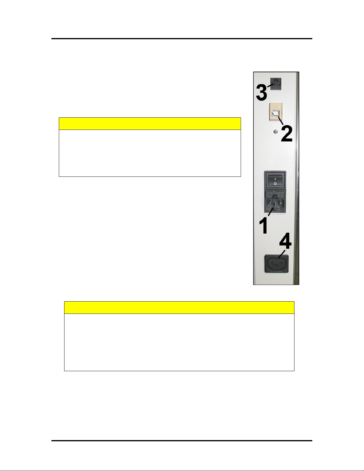
•Check to make sure the Main Power Switch [1] is in the OFF (0) position.
•Plug the power cord into the receptacle [1] at the rear of the Printer.
•Connect the other end of the Power Cord to a compatible AC Outlet that
supplies 100-120 volts AC, 60 Hz and provides earth ground.
•Plug the optional High Capacity Output Stacker into the receptacle [4].
CAUTION
DO NOT USE AN ADAPTER PLUG OR EXTENSION CORD TO
CONNECT THE PRINTER TO THE WALL RECEPTACLE.
DO NOT USE OUTLETS CONTROLLED BY WALL SWITCHES.
DO NOT USE AN OUTLET THAT SHARES THE SAME CIRCUIT
WITH LARGE ELECTRICAL MACHINES OR APPLIANCES.
Powering the Printer ON and OFF
Powering-Up the Printer:
1. Turn ON the Main Power Switch [1].
2. Press the Control Panel’s ON/OFF Button.
Wait about 45 seconds for the print engine to power-up (ON/OFF
button will illuminate).
Powering-Down the Printer:
1. Press the Control Panel’s ON/OFF Button.
Wait for the print engine to power-down (all Control Panel Buttons
will turn OFF).
2. Turn OFF the Main Power Switch [1].
CAUTION
BEFORE POWERING OFF THE MAIN POWER SWITCH, ALWAYS POWER
DOWN THE PRINT ENGINE, USING THE ON/OFF BUTTON.
IF THIS RULE IS NOT FOLLOWED DAMAGE TO THE PRINTHEAD AND OR INK
SYSTEM CAN RESULT.
FOR BEST SYSTEM PERFORMANCE; IT IS RECOMMENDED TO KEEP THE
PRINT ENGINE POWERED-UP (ON/OFF LIGHT ILLUMINATED) AT ALL TIMES.

SECTION 2
INSTALLING THE PRINTER
12
Connecting to the Computer
The Printer connects to the computer through the USB port [2].
A Network port [3] is also provided; for connecting the printer to a network
environment.
IMPORTANT: Do NOT connect the printer to the computer, until prompted to do so,
during the printer driver installation process. See “Installing the Printer Software”
section.
Before installing the printer software (Toolbox and Driver); you should temporarily
disable all Antivirus programs and Firewalls. In addition; you must be logged onto the
system with full administrative privileges (admin rights).
Minimum Computer System Requirements
•Operating System: Windows 8/8.1, Windows 10 (Desktop Mode only*). Windows XP, Windows
Vista, Windows 7.
Supports 32 & 64 bit systems.
You must have administrative privileges on the system.
•Pentium II, 2 GHz minimum (Pentium Dual Core, 2.5 GHz or better, is optimal)
•System memory – 2 GB minimum; or as recommended for your operating system.
•At least 10 GB free hard-disk space.
•Web Browser: Firefox recommended; Chrome, Safari, and Opera also supported.
•CD/DVD drive
•USB 2.0/3.0 port (ports will be identified as “USB2”, “USB3” or “Enhanced” in the Device
Manager)
•Microsoft .Net Framework version 3.5 (for 32 bit systems) or Microsoft .Net Framework version 4
(for 64 bit systems) must be installed.
Note: Even if you have a higher .NET Framework version installed; version 3.5 or 4 must also be
installed, or the Toolbox will not open.
Known limitations when used on Windows 8/8.1/10
•The Toolbox is not compatible with the Microsoft Edge browser.
Please use Internet Explorer, Firefox, or Chrome instead.
•Use in “Desktop Mode” only.
•Printing is not supported for “native” Windows 8/8.1/10 applications (apps that were developed
strictly for Windows 8/8.1/10).
•Windows 10 users: The uninstall feature will not appear under All Apps, Memjet.
To uninstall the driver; go to “Settings”, “System”, “Apps & features”. Then locate and uninstall
the “M Series Driver”.
How to check your system for the minimum system requirements, shown above:
Right click on "My Computer" and select Properties. The system information, including Operating System,
Processor Info and Memory info will be displayed under the "General" tab.
How to check your system for the versions of "Microsoft .NET Framework” installed.
From the Control Panel; open "Add or Remove Programs" and look for "Microsoft .NET Framework 3.5..."
or "Microsoft .NET Framework 4..."in the list.
You can obtain "Microsoft .Net Framework 3.5 or 4" via the Microsoft website. http://www.microsoft.com

SECTION 2
INSTALLING THE PRINTER
13
Installing the Printer Software (Driver & Toolbox)
For the Printer software to operate properly check that the computer system meets the minimum
requirements. See section titled “Minimum Computer System Requirements”, on previous page.
NOTE: If you are updating the MACH 8 (M Series) printer software (printer driver and toolbox utility);
please be sure to Uninstall the old software before installing the new software. Use the “Uninstall” feature
found on your computer system under All Programs, “Memjet”, “M Series Driver”.
IMPORTANT: Before installing the Printer software (Toolbox and Driver), you should temporarily
disable all antivirus programs and firewalls. In addition, you must be logged onto the system with full
administrative privileges (admin rights).
NOTE: Even if you plan to use the printer via an Ethernet Network Connection; your initial connection to
the printer must be done via USB; in order to access the Network Configuration Settings in the Toolbox.
Do NOT plug in the USB cable until prompted to do so.
PROCEDURE
NOTE: This process may take up to 20 minutes to complete; please be patient.
1. Disconnect the USB cable connection from the printer; if you plugged it in already.
2. Power-up the Printer. Turn ON the Main Power Switch, then press the Control Panel’s ON/OFF
button. Wait about 45 seconds for the print engine to power-up (ON/OFF button will illuminate).
3. Insert the CD, supplied with the printer, into your CD drive. If the “Launch Menu” window does
not automatically open in your browser. Locate and run the “MENU_LAUNCH.htm” file, located
on the root directory of the CD.
4. When the Operation CD “Launch Menu” window opens on the computer screen; Click “Install
Printer Software”.
NOTE: If you receive a Windows security or authorization warning, click on “YES” or “Continue
Anyway”.
Tip: If you are unable to start the software installation using the button in the “Launch Menu”;
browse to the CD. Locate and open the Printer Drivers folder. Located and run “WinSetup.exe” to
start the install.
5. The “Install Printer Software” window opens
on the computer screen.
Make sure the computer system meets the
minimum requirements and you have followed
the other instructions on the screen. Click
“Install Printer Software”.

SECTION 2
INSTALLING THE PRINTER
14
6. The License Agreement window opens. Carefully
read the “Software License Agreement”. If you
agree to the terms, check “I accept…” then click
Next>.
7. After a few moments the “Printer Connections”
window opens. Click “Configure to print using
USB”. Then click Next>.
NOTE: Even if you plan to use the printer via an
Ethernet Network Connection; your initial
connection to the printer must be done via USB;
in order to access the Network Configuration
Settings in the Toolbox.
8. After a few moments the “Installing Printer
Software” window opens and begins
downloading the software.
9. As the software loads, the “Would You Like to
Install This Device Software?” window
appears. Click Install.
10. The “Connect Device Now” window opens.
Connect the USB cable, from the computer to
the printer, at this time.
Don’t click on either button (Back or Cancel).
The software will automatically continue once it
recognizes the printer (printer powered on and
USB cable connected).
This manual suits for next models
1
Table of contents
Other Memjet Printer manuals

Memjet
Memjet AFINIA LABEL L701 Series User manual

Memjet
Memjet icube 1-3 Owner's manual

Memjet
Memjet Printware iJetColor Press Service manual

Memjet
Memjet AstroJet M1 User manual

Memjet
Memjet MACH 8 User manual

Memjet
Memjet VIPColor VP750 User manual

Memjet
Memjet C6010 User manual

Memjet
Memjet MACH 5 User manual

Memjet
Memjet OWN-X Speedstar 1000 Instruction manual

Memjet
Memjet AstroJet M1 User manual


