Mercia Garden Products 0628WKNE0405LBDD2SW-V1 User manual

P 1
0628WKNE0405LBDD2SW-V1
28MM LOG CABIN, WORKSHOP, NO EXTRAS, 4X5, LEDGED BRACED DOUBLE DOORS, TWO SHORT WINDOWS
2mm Drill bit
Winter = High Moisture = Expansion
Summer = Low Moisture = Contraction
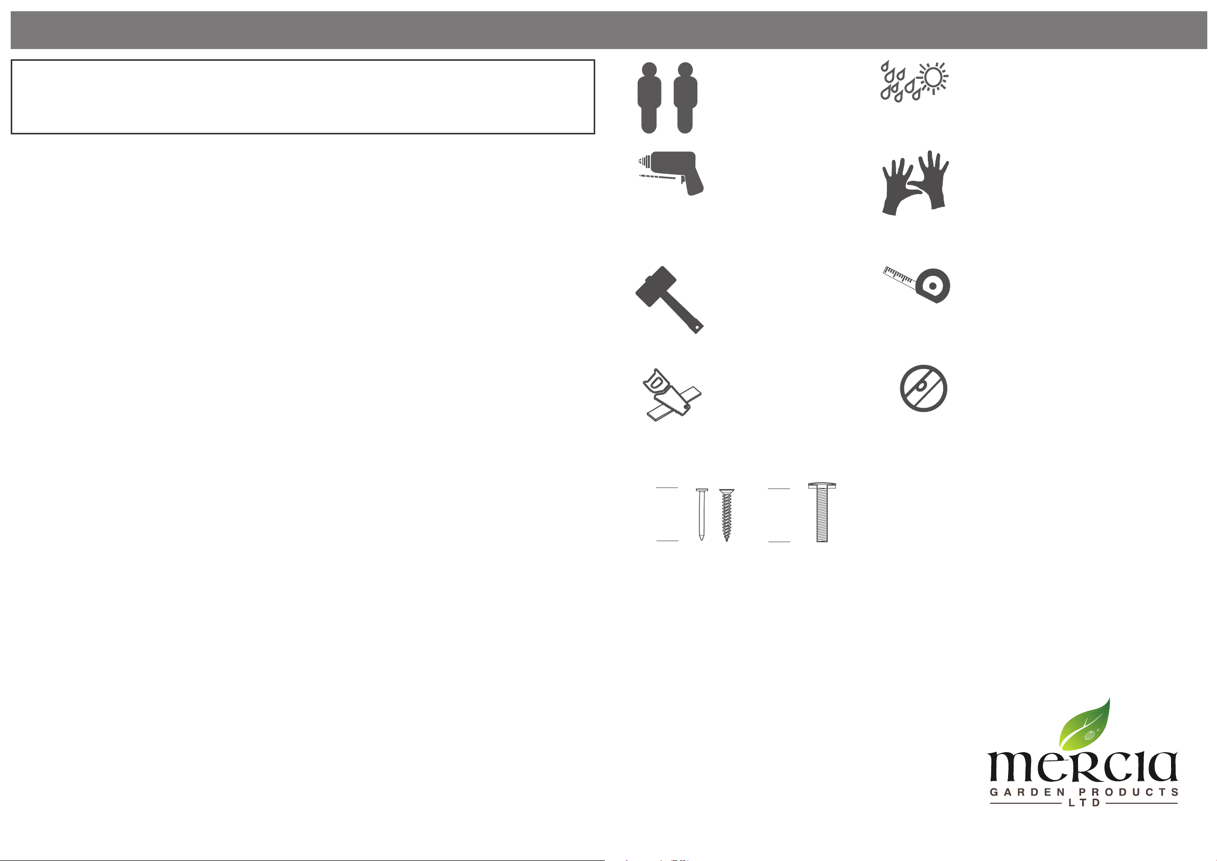
All buildings should be
erected by two adults
For ease of assembly, you
MUST pilot drill all screw
holes and ensure all screw
heads are countersunk.
CAUTION
Every eort has been made during the
manufacturing process to eliminate the
prospect of splinters on rough surfaces of the
timber. You are strongly advised to wear gloves
when working with or handling rough sawn
timber.
Please retain product label and instructions for future reference
General Instructions
BEFORE YOU START PLEASE READ INSTRUCTIONS CAREFULLY
- Check the pack and make sure you have all the parts listed.
- When you are ready to start, make sure you have the right tools at hand (not supplied)
including a Phillips screwdriver, Stanley knife, wood saw, step ladder and drill with 2mm
bit.
- Ensure there is plenty of space and a clean dry area for assembly.
TIMBER
As with all natural materials, timber can be aected during various weather conditions.
For the duration of heavy or extended periods of rain, swelling of the wood panels may
occur. Warping of the wood may also occur during excessive dry spells due to an interior
moisture loss. Unfortunately, these processes cannot be avoided but can be helped. It is
suggested that the outdoor building is sprayed with water during extended periods of
warm sunshine and sheltered as much as possible during rain or snow.
BUILDING A BASE
When thinking about where the building and base are going to be constructed:
Ensure that there will be access (60cm) to all sides for maintenance work and annual
treatment.
Ensure the base is level and is built on rm ground, to prevent distortion. Refer to
diagrams for the base dimensions. The base should be slightly smaller than the external
measurement of the building, i.e. The cladding should overlap the base, creating a run
o for water. It is also recommended that the oor be at least 25mm above the
surrounding ground level to avoid ooding.
TYPES OF BASE
- Concrete 75mm laid on top of 75mm hard-core.
- Slabs laid on 50mm of sharp sand.
Whilst all products manufactured are made to the highest standards of Safety and in
the case of childrens products independently tested to EN71 level, we cannot accept
responsibility for your safety whilst erecting or using this product.
Refer to the instructions pages for your specic product code
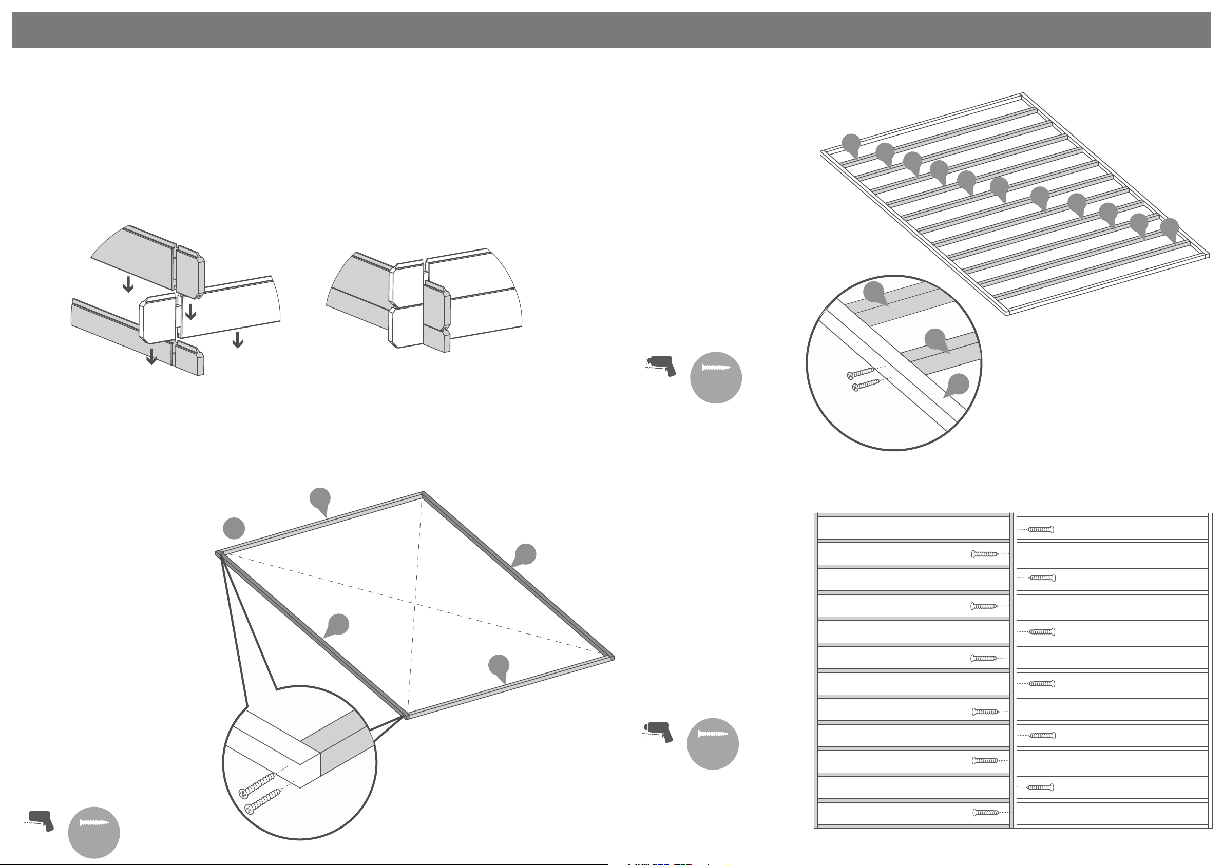
For ease of assembly use a
rubber mallet to t the log
boards. Do NOT use a heavy
hammer.
Ensure to measure and check before cutting
boards.
For assistance please contact customer care on: 01636 821215
Mercia Garden Products Limited,
Sutton On Trent,
Newark,
Nottinghamshire,
NG23 6QN
www.merciagardenproducts.co.uk
It is advisable to use a hand
saw when cutting roof and
oor boards.
To ensure log boards are even, use a spirit
level to check each layer has been installed
correctly.
Measure
under the
head
Measure
overall
length
Screws & Nails Bolts To identify the
xings required
for each step use a
measuring tape.

P 2
Please retain product label and instructions for future reference
0628WKNE0405LBDD2SW-V1
Overall Dimensions:
Width = 4110mm
Depth = 5036mm
Height = 2734mm
Base Dimensions:
Width = 3808mm
Depth = 4808mm
Before assembly
please make sure you have a
suitable base ready to erect your
building
MADE IN GREAT BRITAIN
Window Contents
2
1
3
4
Window Qty 2
AI-06LOGDGW684X1244-V3
5
Window Frame Left Upright - 71x70x1412mm Qty 2
AI-0628LOGWUFL-V3
Window Frame Right Upright - 71x70x1412mm Qty 2
AI-0628LOGWUFR-V3
Window Frame Top - 81x125x805mm Qty 2
AI-0628LOGSWTF-V3
Window Frame Bottom - 71x70x805mm Qty 2
AI-0628LOGSWBF-V3
7
Flag Hinge QTY 4
PI-07-0211
8
Double Door Contents
10
9
11
12
Dead Lock
Qty 1
PI-07-0200
Key Plate
Qty 1
PI-07-0200
Pad Bolt
QTY 2
PI-07-0183
Master Door
Qty 1
(Morticed for lock)
AI-06LOGWKLBMD750X1900-V1
13
14
15
17 18 19 20 21
Slave Door
Qty 1
AI-06LOGWKLBSD750X1900-V1
Door Frame Left Upright - 71x70x2065mm Qty 1
AI-0628LOGDUFL-V3
Door Frame Top - 81x125x1632mm Qty 1
AI-0628LOGDDTF- V3
Door Strip - 16x60x1880mm Qty 1
S1660-1880mm
Door Frame Right Upright - 71x70x2065mm Qty 1
AI-0628LOGDUFR-V3
Door Frame Bottom - 71x70x1508mm Qty 1
AI-0628LOGDDBF-V3
6
16
Rain Guards QTY 2
RG2844-710 (28x44x710mm) Rain Guard QTY 1
RG2844-1520 (28x44x1520mm)
Hook & Band Hinge
QTY 6
PI-07-0219
Pull Handle
QTY 2
PI-07-0032
Casement Stay Qty 2
PI-07-0187

P 3
Please retain product label and instructions for future reference
22
Gable - 4000mm
QTY 2
AI-0628WKNE0405LBDD2SW-G-V1
23
Starter Board - 66x28x4000mm QTY 2
LB28RT66-A-4000
24
Log Board - 120x28x4000mm QTY 19
LB28-A-4000
25
Log Board - 120x28x3036mm QTY 12
LB28-B-3036
26
Log Board - 120x28x232mm QTY 30
LB28-B-232
Log Board - 120x28x232mm QTY 12
LB28-C-232
27
Log Board - 120x28x5000mm QTY 26
LB28-A-5000
Log Board - 120x28x2200mm QTY 18
LB28-B-2200
Log Board - 110x28x5000mm QTY 1
LB28RG110-A-5000
Roof Purlin - 45x120x5004mm QTY 3
F45120-A-5004
Bearer - 44x44x2316mm QTY 26
F4444-2316-PT
Bearer - 44x44x3808mm QTY 4
F4444-3808-PT
Fascia - 120x16x2118mm QTY 4
S16120-G-2118 (1X14° CUT)
Floor Board - 121x16x3752mm QTY 44
MB16-3752
Roof Board - 121x16x2114mm QTY 92
MB16-2114
Storm Brace - 27x44x2000mm QTY 8
F2744-2000
Log Board - 120x28x4000mm QTY 1
LB28-AD-4000
Log Board - 110x28x5000mm QTY 1
LB28RG110-AD-5000
Closure Trim - 16x28x2400mm (approx length) QTY 16
S1628-C-2400
28
29
30
31
32
33
34
35
36
40
41
Eaves Frame - 27x44x2502mm QTY 4
F2744-2502
37
38
39
42
43
Felt
Roof Spacers QTY 5
PI-07-0208 (20x100x2mm)
Main Building Contents
Felt Tacks x 320
70mm Screw x 145
Nail Bag
40mm Screw x 820
30mm Screw x 162
70mm Bolt Set x 16
There may be extra screws present in the nail bag
30mm Black Screw x 8
80mm Screw x 24

For assistance please contact customer care on: 01636 821215
Mercia Garden Products Limited,
Sutton On Trent,
Newark,
Nottinghamshire,
NG23 6QN
www.merciagardenproducts.co.uk
P 4
Please retain product label and instructions for future reference
Pre-assembly
*Please note:
Each board interlocks at
either end in a staggered pattern.
Before securing ensure that the boards
are tted properly in their respective
tongues and grooves.
IMPORTANT: Pre-drill before xing screws.
32
32
31
31
Pre drill
hole
70mm
screw
Step 1
Parts needed - No. 31 QTY 13
No. 32 QTY 2
Lay the bearers (No’s 31 & 32) onto a
rm and level surface (free from
areas where standing water can
collect) as shown in the illustration.
Fix the framing together at each
corner using 8x70mm screws,
ensuring the frame is ush.
Once fully assembled, ensure the
bearers are square by measuring
from corner to corner as illustrated,
making sure the measurements are
equal.
If the bearers are not aligned equal-
ly, unscrew, adjust and re-align
accordingly.
8x70mm Screws
a
Example picture
2 screws per bearer per end.
=
=
IMPORTANT: Pre-drill before xing screws.
31
31
Pre drill
hole
70mm
screw
Step 2
Parts needed- No. 31 QTY 11
Following the same method
arrange the remaining framing
(No. 31) inside the assembled
frame.
*Ensure there is an equal
amount of space between
each frame.
Secure each of the frames in
place using 2x70mm screws
for each side of the bearer,
ensuring the framing remains
level.
44x70mm Screws
31 31 31 31 31 31 31 31 31 31 31
32
Pre drill
hole
70mm
screw
Step 3
Parts needed- No. 31 QTY 13
No. 32 QTY 2
Repeat Steps 1 & 2 to create the
second base section.
*Ensure there is an equal
amount of space between each
frame.
Once built secure both base
sections together using 70mm
screws as shown in the
illustration.
64x70mm Screws
IMPORTANT: Pre-drill before xing screws.

P 5P 3P 5
Please retain product label and instructions for future reference
Once the boards are square, lift up the log board (No. 27) and x the
starter boards in place.
Fix each of the starter boards to the frame by screwing through the
notch into the frame as shown in the illustration.
4x70mm Screws
23
Pre drill
hole
70mm
screw
Step 4
Parts Needed - No. 23 QTY 2
No. 27 QTY 2
Place the starter boards (No’s. 23) on to assembled base frame along the
shortest sides and place the rst two log boards (No. 27) in the notch as
shown.
Ensure the boards sit square on the base using the same method used
in Step 1. Measure corner to corner, making sure the measurements are
equal.
27
23
IMPORTANT: Pre-drill before xing screws.
23
23
27
27
Step 5
Parts Needed - No. 24 QTY 6
No. 26 QTY 6
No. 27 QTY 12
No. 28 QTY 6
Following the method shown in
the illustration, lay the rst 6
boards (No’s. 24, 26, 27 & 28)
onto the starter boards to create
your rst level.
*Make sure that you have seven
rows of log boards in total
below the window.
*Ensure that the boards are
level and ush with each
other as you lay each one.
**Please Note: The short boards
at the front of the building (either
side of the door and window
opening’s) can be placed either
side depending on your needs.
27
24
27
28
26
Rubber Mallet
may be required
to t parts.

P 6
Please retain product label and instructions for future reference
Step 6
Parts Needed - No. 11 QTY 1
No. 12 QTY 1
No. 13 QTY 1
No. 14 QTY 1
Arrange the left, right, top & bottom door
frames (No’s. 11, 12, 13 & 14) onto a level
surface. Secure the top and bottom frames to
the uprights using 2x80mm screw per corner,
ensuring the screws do NOT protrude through
the front of the door framing.
8x80mm Screws
Pre drill
hole
80mm
screw
14 12
IMPORTANT : Pre-drill before xing screws.
The internal lip of the door
frame should be postioned on
the inside of the building.
14 12
13
11
IMPORTANT : Pre-drill before xing screws.
Pre drill
hole
Step 7
Parts Needed - No. 9 QTY 1
No. 10 QTY 1
No. 17 QTY 6
Fasten six hinges (No. 17) to the door and the frame with
the screws supplied with the hinges. Make sure that the
screws t evenly into the framing on the otherside of the
door. Also make sure that there is an equal 3mm spacing
between the doors and the framing.
The doors should t evenly within the framing. Make sure
that there is an equal 3mm spacing between the doors and
the framing.
It is important to t the doors within the frames at this
stage so that you can establish the position of the hinges.
The hinges come in two parts. Remove Doors from frame
after tting.
CAUTION: THESE DOORS ARE EXTREMELY HEAVY!
10
9
17

P 7
Please retain product label and instructions for future reference
Step 8
Once you have laid 6 log boards (on top of the
starter board) up the door section, slide the
assembled door frame (without main doors)
over the boards resting the frame on top of the
starter board (if you have not yet assembled the
door frame refer to step 6 & 7.)
*Please note: This image is for illustrative purposes
and may dier from your choice in product
(regarding door position). Nevertheless the
process of tting the door frame is the same.
**Please Note: The short boards at the
front of the building (either side of the door and
window opening’s) can be placed either side
Step 9
Parts Needed - No. 24 QTY 6
No. 25 QTY 6
No. 26 QTY 12
No. 27 QTY 6
No. 28 QTY 6
No. 38 QTY 6
Following the method shown in the
illustration, lay the next 6 boards
(No’s. 24, 25, 26, 27 ,28 & 38) onto
the log cabin to create your second
level.
*Make sure that there are seven
rows of log boards in total below the
window.
*Ensure that the boards are level
and ush with each other as you lay
each one
26
28
25
38 26
27
24
Rubber Mallet
may be required
to t parts.

P 8
Please retain product label and instructions for future reference
2
4
IMPORTANT : Pre-drill before xing screws.
Step 10
Parts Needed - No. 2 QTY 2
No. 3 QTY 2
No. 4 QTY 2
No. 5 QTY 2
Arrange the left, right, top & bottom window
frames (No’s. 2, 3, 4,& 5) onto a rm and level
surface. Secure the top and bottom frames to
the uprights using 2x80mm screw per corner,
ensuring the screws do NOT protrude through
the front of the window framing. Using the
method outlined assemble two window
frames.
16x80mm Screws
Pre drill
hole
80mm
screw
5
3
53
The internal lip of the window
frame should be postioned on
the inside of the building.
30mm
screw
Step 11
Parts Needed - No. 1 QTY 2
No. 7 QTY 4
Position the window (No. 1) so that it
sits centrally within the window frame.
Fix the female part of the ag hinge
(No. 7) to the window using 4x30mm
screws, attach the male part of the ag
hinge (No. 7) to the window frame using
4x30mm screws ensuring that the window
can open and close freely.
It is important to t the windows within the
frame at this stage so that you can establish the
position of the hinges. The hinges come in two
parts. Remove the window from the frame after
tting.
*Ensure to attach the hinge to the horizontal
frame of the window*
Repeat this method for both windows.
32x30mm Screws
Pre drill
hole
IMPORTANT : Pre-drill before xing screws.
7
7
7
1
Step 12
Once you have laid the second
level of boards onto the log cabin
slide the window frames (without
window No. 1) between the smaller
boards and rest on to the longer
board (if you have not yet assembled
the window frames refer to step 10).
*Ensure the boards are level with
each end.
*Please note: This image is for
illustrative purposes and may
dier from your choice in product
(regarding window position).
Nevertheless the process of tting
the window is the same.

P 9
Please retain product label and instructions for future reference
Step 13
Parts Needed - No. 24 QTY 6
No. 25 QTY 6
No. 26 QTY 12
No. 27 QTY 6
No. 28 QTY 6
No. 38 QTY 6
Following the method shown in
the illustration, lay a further 6
boards (No’s. 24, 25, 26, 27, 28 &
38) onto the log cabin to bring the
board level to the top of the
window and door frames.
*Ensure that the boards are
level and ush with each
other as you lay each one.
*Doors can be hung once the
boarding has enclosed the
door frame.
38
28
24
26
27
25
26
Rubber Mallet
may be required
to t parts.
Step 14
Parts Needed - No. 24 QTY 1
No. 29 QTY 1
No. 36 QTY 1
No. 37 QTY 1
Following the method shown in the
illustration, lay the last two boards
(No’s. 24 & 36) onto the front and
rear of the log cabin.
Once in position place the last
two boards (No’s. 29 & 37) onto
the window and plain side.
*Ensure that the boards are
level and ush with each
other as you lay each one.
36
29
24
37
Rubber Mallet
may be required
to t parts.

P 10
Please retain product label and instructions for future reference
Step 15
Parts Needed - No. 22 QTY 2
Place the gable tops (No. 22)
onto the log cabin. Fix into
position by screwing through
the notches as shown in the
illustration.
*Ensure that the boards are
level and ush with each
other as you lay each one.
4x70mm Screws
Pre drill
hole
70mm
screw
IMPORTANT: Pre-drill before xing screws.
22
22
Rubber Mallet
may be required
to t parts.
Pre drill
hole
70mm
screw
30
30
30
a
b
Step 16
Parts needed - No. 30 QTY 3
Align the Roof Purlins (No. 30)
into the cut out slots on each gable top
ensuring each purlin interlocks into the
boards.
Secure the purlins at each end
by screwing through the roof purlins
into the boards (ensure to pre-drill to
avoid the boards splitting) using
4x70mm screws per purlin.
*Please note: The gable shown is for
illustrative purposes and may dier
in width from your choice in product.
Nevertheless, despite any dierences
the process of xing the purlins
is the same.
12x70mm Screws
a
b
IMPORTANT: Pre-drill before xing screws.
Rubber Mallet
may be required
to t parts.

Please retain product label and instructions for future reference
P 11
40mm
screw
Pre drill
hole
*Cut to t
Step 17
Parts needed - No. 40 QTY 92
Place the rst two roof
board’s (No. 40) onto the log cabin
on each side, making sure the
boards are ush to the end of the
roof purlin. Once in position x to
each purlin using 3x40mm screws.
Use the spacer (No. 43) to create an
expansion gap between each roof
board if installing during low levels
of moisture (summer). This creates
an expansion gap for the boards to
move into during high levels of
moisture (winter).
Once in position x to each purlin
using 3x40mm screws.
You have been issued with 92 roof
boards, but in reality you may only
need to use 90
*Ensure the roof boards meet at
the top of the apex and leave an
overhang at the bottom.
Continue adding the roof boards
along the roof, xing each one into
position using 3x40mm screws,
making sure that each board is
interlocked, ush at the bottom &
meet at the top of the apex.
The last board on each side
will overhang: Using a straight edge
and a pencil mark out a line as
a guide.
Cut along the pencil mark and
remove the excess. Place the cut
down board’s back onto the roof
and secure into place using
3x40mm screws per board.
276x40mm Screws
a
b
IMPORTANT: Pre-drill before xing screws.
*Please Note: This image is for
illustrative purposes and may
dier from your choice in product.
Nevertheless the process of
cutting and tting the last roof
board(s) is the same.
b
23b 40
40
a
Step 18
Parts Needed - No. 35 QTY 4
Ensuring the roof boards are ush
at the overhanging side and meet
at the apex, x the eaves frames
(No. 35) to the underside of the roof
boards using 9x30mm screws as
shown in the illustration
*Please Note: This image is for
illustrative purposes and may
dier from your choice in
product. Nevertheless the process
of xing the eaves frames is the
same.
18x30mm Screws
30mm
screw
Pre drill
hole
IMPORTANT: Pre-drill before xing screws.
35

Please retain product label and instructions for future reference
P 12
39
Step 19
Parts Needed - No. 39 QTY 44
Place the rst oor board (No. 39)
inside the building ush to the log
board on one side. Continue adding
the oor boards (internally) making
sure to interlock each individual
board.
You have been issued with 44 oor
boards, but in reality you may
only need to use 43.
*Do NOT secure the boards until
the last board has been measured
and cut.
Following the same method outlined
previously measure the gap between
the bottom of the tongue (on the last
board placed) and the log board.
Using a straight edge mark out the
measurement onto the last oor
board (No. 39) and cut along the
length removing the excess.
**Please note: Mark the nal board
2mm under the measurement; This
will allow the timber to expand and
contract correctly.
Once all the oor boards are in
position secure each board into
position using 12x40mm screws.
***Please Note: Ensure to screw
through eachof the oor boards
into the oor bearers.
528x40mm Screws
40mm
screw
Pre drill
hole
*Cut to t
IMPORTANT: Pre-drill before xing screws.
Closure Trim
Internal
23
*Measure and cut the
closure trims to
t the internal space.
Closure Trim
Internal
33
*Measure and cut the
closure trims to
t the internal space.
Pre drill
hole
30mm
screw
*trim to t
Step 20
Parts needed - No. 33 QTY 8
Inside the building place the closure
trim (No. 33) against the boarding
and align with the roof as shown in
the illustration.
*Measure and cut the closure trims
to t the internal space.
Once in position x each trim
into place by pre drilling a pilot hole
and using 6x30mm screws per trim,
equally spacing them along the face
of the board.
48x30mm Screws
RoofRoof
IMPORTANT: Pre-drill before xing screws.
23
23
33
33
30mm
screw
Pre drill
hole
*Cut to t
Step 21
Parts needed - No. 33 QTY 8
Once the oor has been laid arrange the
closure trim (No. 33) around the outside
edge of oor (internally), measure and cut
down accordingly to best match the
internal space.
Secure each trim section into place using
6x30mm spaced equally along the board
as shown in the illustration.
*Do NOT x the closure trim to the oor
boards.
48x30mm Screws
IMPORTANT: Pre-drill before xing screws.

Please retain product label and instructions for future reference
P 13
Step 23
Parts Needed - No. 34 QTY 4
Align the fascia’s (No. 34) with
the roof and x into place
using 3x40mm screws per
fascia, making sure to screw
through the fascia into the
roof purlins and eaves frame.
*Ensure the angled cuts meet
at the top of the apex.
12x40mm Screws
Pre drill
hole
40mm
screw
IMPORTANT: Pre-drill before xing screws.
Felt
tacks
Step 22
Parts needed - No. 42
Cut the felt (No. 42) into ve strips and
lay onto the roof in the order shown
in the illustration.
*Ensure there is approximately 50mm
of overhanging felt each side.
Once the felt is laid out x to the
roof using felt tacks at 100mm
intervals.
*Felt size: 5100mm
320x Felt Tacks
HANDLE
WITH CARE
12
3
4
1.
2.
3.
4.
5.
42
34
34
34
34

Please retain product label and instructions for future reference
P 14
Pre drill
hole
70mm
bolt
Step 24
Parts needed - No. 41 QTY 8
Arrange the storm braces (No.41)
around the building (internally).
Place 2x storm braces per side
xing into place using 2x 70mm
bolts per brace making sure the
washer & nut are tightened from
the outside of the building.
*Ensure the storm braces are
secured at the highest point
possible on each side.
The storm braces will need
to be altered during the buildings
life as the moisture content within
the log boards changes. The boards
will expand during periods of high
moisture (Winter) and shrink during
periods of low moisture (Summer.)
**Storm braces will help your
building expand and contract
properly.
***Important: Ensure each
bolt is tightened using a
washer so as not to damage
the log boards.
16x70mm Bolt Sets
41
41
Step 25
Lift each door onto the
already existing hooks on the
Garage door frame, ensuring
the hook and bands connect.
*Some adjustment may be
required to align properly.
CAUTION: THESE DOORS
ARE EXTREMELY HEAVY!

Please retain product label and instructions for future reference
IMPORTANT : Pre-drill before xing screws.
Pre drill
hole
30mm
screw
Step 26
Parts Needed - No. 18 QTY 2
No. 19 QTY 1
No. 20 QTY 1
Fit the Dead Lock (No. 19) into the recess
in the master door (No. 9) and secure
using the screws provided. Attach the Key
Plate (No. 20) to the slave door (No. 10)
with 4x30mm screws.
After xing the Dead lock, add the pull
handles (No. 18) with 4x30mm black
screws each. Be sure that the screws x
into the framing on the otherside of the
door.
**You have been provided with an
additional set of pull handles (No. 18).
These can be used internally on the
Garage doors, dependant on your wants
and needs. Ensure to stagger screws so
they do not collide.
*Please note: This image is for illustrative
purposes and may dier from your choice in
product (regarding ironmongery). Never-
theless the process of xing is the same.
8x30mm Black Screws
4x30mm Screws
30mm
screw
The Lock is Reversible
a
20
9
10
18
19
19
P 15
a
b
c
c
Step 27
Parts Needed - No. 15 QTY 1
No. 21 QTY 2
Attach the Door Strip (No. 15) to the
back of the slave door using 4x40mm
screws as shown.
Once xed, place the Pad
Bolts (No. 21) roughly into
position and with a pencil
mark the around the bolt.
After marking the bolt onto
the frame, drill a hole for the
barrel bolt to locate into.
Following the hole being
drilled, place the pad bolts
into position and secure using
the screws provided.
4x40mm Screws
Pre drill
hole
40mm
screw
IMPORTANT : Pre-drill before xing screws.
b
a21 15

Please retain product label and instructions for future reference
P 16
Step 28
Lift each window onto the already existing
hooks on the window frame, ensuring the
hook and bands connect.
*Some adjustment may be required to
align properly.
Pre drill
hole
30mm
screw
Step 29
Parts Needed - No. 8 QTY 2
Fix the casement stay (No. 8) onto the
window (No. 1) and the casement stay pins
to the window framing using 6x30mm
screws.
*Ensure the casement stay is centralised on
the window.
Use this method to t the casement stays to
both the windows.
12x30mm Screws
8
1
8
Step 30
Parts Needed: No. 6 QTY 1
No. 16 QTY 1
Attach the Rain Guard (No. 6) to the
Window frame, xing in place onto the
framing above each window using
3x70mm screws per guard.
Attach the Rain Guard (No. 16) to the
Door frame, xing in place onto the
framing above the Door using
3x70mm screws.
9x70mm Screws.
70mm
screw
Pre drill
hole
66
6
16
16
It is ESSENTIAL that you apply wood
treatment immediately after the building
has been assembled.
Table of contents