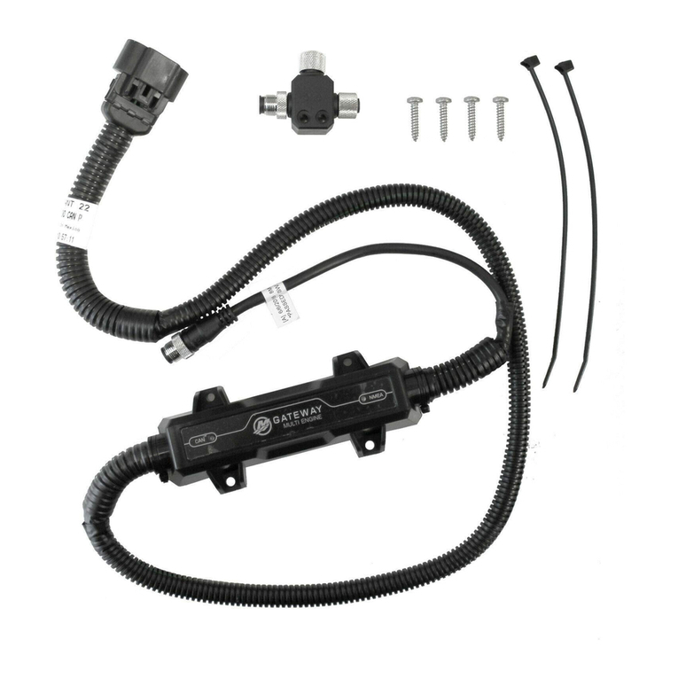
SMARTCRAFT TRIM POSITION SENSOR AND ANALOG SENDER KIT
Page 2 / 8 © 2016 Mercury Marine 90-8M0119720 eng MAY 2016
Removal
NOTE: Refer to
MerCruiser Bravo Sterndrives Service Manual #39
or,
MerCruiser Alpha Sterndrives Service Manual
#14
for sterndrive removal, bell housing separation, and installation procedures that are required to access the sensor
harness clamp plate screw.
1. Remove the sterndrive and separate the bell housing from the gimbal ring and U‑joint bellows to access the sensor
harness clamp plate and screw. Retain all hardware.
a - Bell housing
b - Gimbal housing
c - Hinge pin backing washer
d - Gimbal ring
2. Disconnect the trim position sensor wiring from the transom harness connector.
3. Disconnect the analog trim sender wiring from the engine harness connector.
4. Remove the clamp plate screw and clamp plate from the gimbal housing.
a - Clamp plate
b - Trim position sensor harness (port)
c - 2‑wire analog sender (starboard)
5. Pull approximately 30 cm (1 ft) of the trim position sensor and analog sender harness out of the gimbal housing.
6. Cut each harness just forward of the tapered plug. Do not remove the harnesses from the gimbal housing. They will be
used to pull the new harnesses through the transom and into the boat.
Installation
1. Tape the connector ends of the new sensor and sender to the cut ends of the old harnesses.
2. Pull the new harnesses through the gimbal housing to the inside of the boat using the old harnesses.
3. Remove and discard the cut sections of the old harnesses.
4. Route the new sensor and sender wires through the hole. Bring together the two grommet halves and ensure that they
are seated tightly in the hole and that the flat edges that mate together are vertically aligned. Maintain light tension on the
wires from inside the boat, to hold the grommets in the hole.
5. Install the clamp plate around both sets of wires and position it while hand starting the clamp plate screw. Ensure that the
trim position sensor (3‑wire) wiring is positioned to the port side of the gimbal housing and the trim position sender is
positioned to the starboard side of the gimbal housing.
6. Apply sealant to the trim harness clamp plate screw threads and install the clamp plate. Tighten the screw to the
specified torque.
Tube Ref No. Description Where Used Part No.
19 Perfect Seal Trim harness clamp plate screw threads 92-34227Q02
