Merkava RF350 User manual

RF350
User Manual
4.
1. carefully remove contents of box out ofthe packaging.
. 1x RF350 eBike
. 1x 110V CharSer
. 1x mud Suard (optional)
. 1 x Rear rack (optional)
. 2xKeys
2. Fold open the eBike and close the quick release latch on the frame.
lnstall Front wheel and tighten quick release latch.
Place handle bar in place and tighten allen screws
Place seat to desired height and tighten quick reiease latch.
lnflate tires to about 35-4OPS
Place your RF350 on a raised surface for easy inspection while securing one of the wheels so
it stavs in place then proceed to visually check the RF350 components and ensure that all
screws and bolts are tightened and that tires are correctly inflated. Check and adiust break
leverto your preference and check that the de ra illeur fu nctions properly. This is usually
already done once at the factory and once before shipping but as a precautionary measure
we recommend you do this as well before riding-
Charge your RF350 in a clean environment at ambient temperature until light on the charger
turns from red to green. You can charge the battery while still inside the frame of the eBike
oryou may remove the battery and charge at independently. To remove the battery pack
open the quick release latch on the frame and fold the eBike, insert the key under the
frame, push and turn it clockwise until the lock pin goes inside the battery- Remove the key
and slowly pull out battery pack. Repeat process in the inverse order to re insert the battery
Pack into frame,
6.
1.
8.
3.
5.
9. Once you've familiarized yourselfwlth the digita I display you willbe readyto ride. Please
ride carefully! {see attached instruction for OMOT-M3 display)
IMPORTANT NOTE: To AVorD DAMAGTNG youR BATTERY pAcKwE srRoNGLy REcoMMENo
USER SHUTS DOWN AND RECHARGE THE RF35O ONC€ BATTERY LEVEL REACHES 1O%. YOU W|LI ENTER
THISCRITICAL LEVEL SHORTIY AFTER YOUR DISPLAYSHOWS 1 BAR OR REACHES 4OV I],I THE VOI.TAGE
METER.

Eefore shipping, each and every transporter ;s checked for overall quality control and condition of
battery pack. Batiery is tested and fully charged before shipping.
The lithium ion technology is intended to last for several years while being charged and discharged many
times. However, the battery's life span willdepend on yourcare of the battery.
Battery life will depend on your maintenance and care ofthe battery. RF350 uses advanced Lithium-lon
batteries made with high capacity LG cells and they should be charged at least once a month (when not
in use) to ensure the longevity of vour battery. Make sure to only use our supplied 48V charger on Your
48V battery.
Allow your battery to rest for 10 minutes after charging before riding and for 10 min after riding before
charging. Unplug your battery charger after the light turns Breen indicating your batterY is fuliY charged.
Always unplug the charge. from the wall outlet before plugging or unplugging the other end into your
RF35O,
Typical charging time after the battery has reached the 10% critical low level is between 5 to 6 hours.
Coutiorj Do not expose your battery to extremely low or high temperatures to avoid potential damage
to your battery.>>
lM PORTANT NOTE: ro Avoro DAMAGTNG YouR BATTERY PACK wE STRoNGLY REcoMMEND
USER SHUTS DOWN AND RECHARGE THE RF35O ONCE BATTERY LEVEL REACHES 1O%. YOU WILL ENTER
THIS CRITICAL I"EVEL SHORTLY AFTER YOUR DISPLAY SHOWS 1 BAR OR REACHES 4OV IN THE VOLTAGE
METER.
Merkava stands behird its products. All our trrnsporters benelit froE r 2 year limitcd
walTanty.
The COMPANY wanants that the frrme will be fiee fiom defects in the materials and
workmanship for a pe od of2 years.
The COMPANY wanants that the motor and battery pack will be free from defects in the
materials and workmanship for a period of 1 yeari.
The COMPANY warrants that the electrical components including the coutroller and
charger will be liee ftom defects in the materials and workmanship for a pedod of 6 months.
Before shipping, we conducl spot checks on our transporters to validate overall quality and
condition ofelectrical components including motor and batlery pack. These checked units have
their battery tested and fully charged before slipping.
The lithium ion technology we use is intended to last for several years while being charged and
discharged many times. However, the battery's life span will depend on your care ofthe battery.
lfthe PRODUCT proves defective AND a claim is filled during the wananty period, the
COMPANY at its option, will:
Repair the PRODUCT by means oftelephone support, email support, or by Foviding the
necessary parts at no charge.
Warranty claims musl be filed with Merkava by email: infolalncrkava.ca
*Wananty on batterv will be lirnited to 6 montlts if il is dcternlincd that our guidclines for propcr
hatterv care have not been followed.
The following are not covered by the warranty:
. wear and tear on frame, grip tape, levers, tubes, tires. brake discs, brake pads, cables,
seats, plastic fairings and any other component which wears out naturally during usage.
. Minor scratches and stress marks thal may occur during shipping and handling.
. Water damage caused by exposing sensitive electrical parls to water such as washing
transporter with hose or pressue washer.
. Accidents, misuse. abuse, human errors or lack ofmaintenance.
. Acts-of--god such as fue, flood, earthquake, freezing, etc

warranty information continued:
The following will void the wrr.antyi
. The modification ofyour hansporter or use outside those specified on this site.
. The serial numbq ofthe product has been altered or removed.
. The product has been dismantled and repaired/reassembled with aftermarket pans.
. Overloadilg your transporter.
. Storing your transponcr ouldoors.
IMPORTANT NOTE: To AvotD DAMAGTNG youR aATTERY pAcK wE srRoNct-y RECoMMEND
USER SHUTS DOWN AND RECHARGE THE RF35O ONC€ BATTCRY LEVEL REACHES 1O%, YOU WILI. ENTER
THIS CRITICAL LEVEI. SHORTI.Y AFTER YOUR DISPTAY SHOWS 1 BAR OR REACHES 4OV IN THT VOI.TAGE
METER.

. Ajways Start in tbe slow Pedaj Assist mode (1)
. Grip both hand grips
. Check brake level for positive braking action
. Turn ignition to ON by inserting the key at the bottom ofthe frame and turning
counter clock wise
. Press the power button on the display {or 2 seconds
. Start pedaling, motor will kick in within a second or two
. Once your comfortable riding the eBike on Pedal Assist Mode you can start using the
throttle instead of pedaling.
. You should only use ONE riding mode at a time. lf using throttle do not pedal. If pedaling
with pedal assist mode do not use throttle.
. Please note, throttle only riding will lower the max range on a charge considerably.
. ALWAYS follow your local laws regarding eBikes and be respectful of other riders on the
road and on trails.
Always wear an A5TM and cPSc certified helmet when riding. Make sure that chin strap is
attached before your ride and follow the helmet manufactures instructions for proper user and
fit.
Make sure to always wear shoes that have good tradion on the pedals and will stay on your
feet-
Squeeze the hand brake levers to ensure there is positive braking action before starting your
ride.
IMPORTANT NOTE: To avorD oAMAGtNG youR BATTERY pAcK wE STRoNGLY RECoMMEND
USER SHUTS DOWN A D iECHARGE TTI€ RF35O O CE BATTERY IEVEL REACHES 10'6. YOU wlLI ENTER
THIS CRITICAL LEVEL SHORTLY AFIER YOUR DISPLAY SHOWS 1 BAR OR REACHES 4OV IN THEVOLTAGE
METER.

2. Overview of OMOT-M3
1) UART protocol:
Equipped with independent press buttons
2) Speed:
Real-time SPEED, MAX SPEED, Average SPEED
kmh/mile,
Kmh/MPH according to habit
Battery level:
lndicates the battery level in real time
Head light control:
pr"* U button for 3 seconds to power on/ofr
Back light adjustment:
3-level adjustment
3)
4)
s)
6)
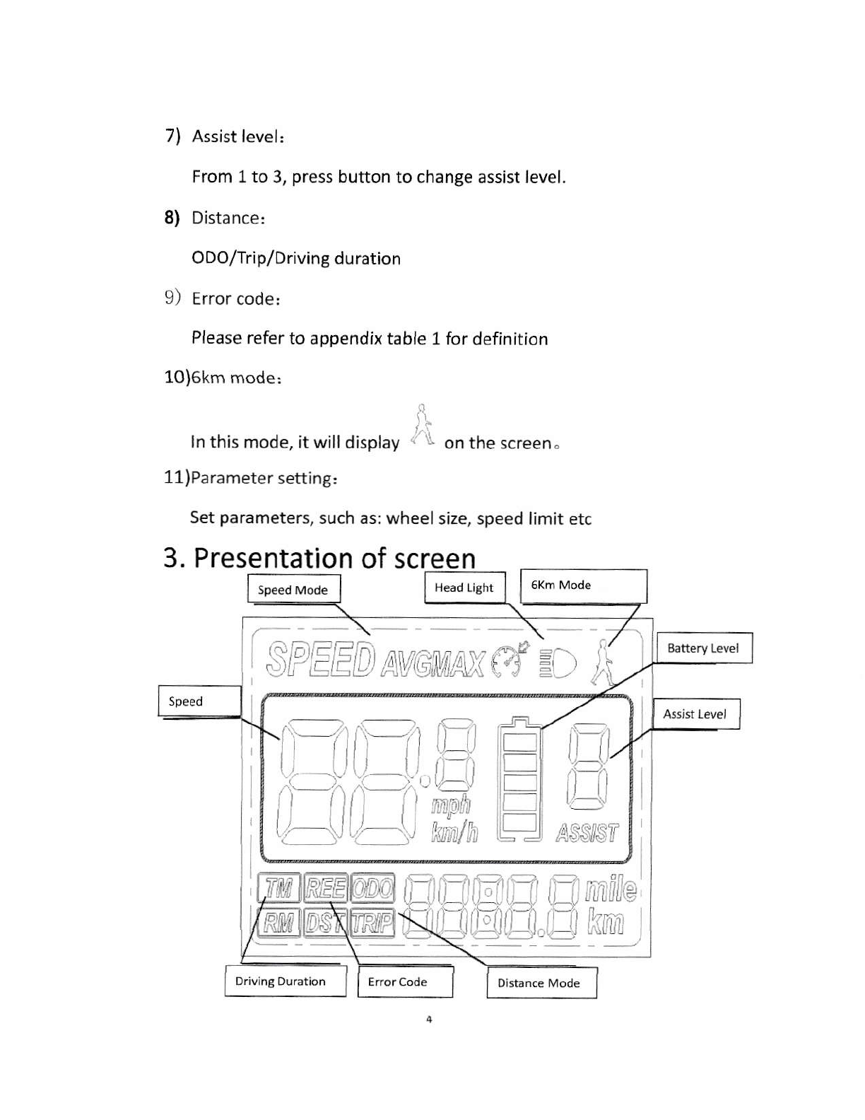
7) Assist level:
From 1to 3, press button to change assist level.
8) Distance:
ODO/Trip/Driving duration
9) Error code,
Please refer to appendix table l for definition
10)6km mode:
ln this mode, it will display on the screen.
11)Parameter setting:
set parameters, such as: wheel size, speed limit etc
A
SFEEDnvomnx# =c i
E
llE
llr-l
llE
LE_
Drlving D!ration
\
^a---1
tn.
i/__i/
ASSSr

1) gattery level: 5levels, voltage intervalcould be customized
2) Speed: Average SPEED/MAX SPEED/Real-time SPEED
3) Speed unit: Kmh/MPH
4) 6km mode: 6km mode Display' -.
5) Assist level' actualassist level 1-3.
6) nead Iight icon: indicates when head light and back light are on.
7) Distance, Trip/oDo.
8) Error code, "REE" and code when there is error
4. Press button definition
OMT-M3 uses independent press button, in total three
buttons;
@ "rr" @ "ro*"," B "ro*'',"
5. Operation instructions
1) Power ON/OFF
When the power is off, Long press @ ( eower) during e
seconds , screen will display all contents and start to normal
working mode, and controller will be turned on When the power is
ffifl
on, Long press ['-l { Power ) during 3 seconds. screen will be
powered off, and controller will be turned off . lf no any operation
both on bike and display during 10 minutes (time could be set), the

display will turn off automatically , in this case, no power
consumption for both display and controller.
Figure 2
2) Different Speed display:
Long prur, @ uno El o switch different speed information,
Real time speed ( SPEED) ) Max speed ( MAX SPEED) )Average
speed ( AVGSPEED )
Figure 3
Real time speed
;tl
fli
flr
SPEED
r-rilsll
i,J,-l^: e '
{:rM I,it.i
;el
f,r
dl
SPFf;D.
rtr-rl'il
f,Frn r !
Lll-r';'= '
{)M I -:,1i
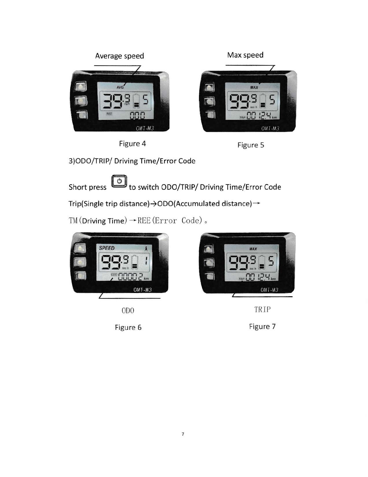
Average speed
Figure 4
3)ODO/TRIP/ Driving Time/Error Code
Max speed
Figure 5
Short press @ro r*n.n oDo/TRIP/ Driving Time/Error Code
frip(Single trip distance))ODo(Accumulated distance)*
TII (Driving Time) .*REE (Error Code) .
0D0
Figure 6
IRIP
Figure 7
:,Ln.l L-,
-l -l = -t-fl-r q tr
-l_1.. = -'
SPEED A
l-,t-l ,:l
-l -l =

Dri v ing
Figu re
4)Assist level
Timo
8
Error Code
Figure 9
short pr.r, G! o,. @ ,o chanSe assist rever,
level 1
Figure 10
5) Head light control
default value is
Figure 11
Long press Etr for. 3 ,".ond. turn onloff the head light.
Level 1Level 5
SPEED
t-1t:.! E
-lr-l'" = -
_rl_qts"; i
A
S'TEEO \
'Il:: :

Head Llght
Figure L2
6) 6km mode H
When the bike is stopped, Iong press LIJ , *;11 enter 5km/h mode,
the speed will be 4.5-7.5km/h according to different road
fr=?
conditions, " " will show up on screen, long press uagain or
short press El, *,, quit 6km/h mode. Long press or short press
could be customized by clients.
6Km Mode
Figure 13
SPEE' ,.
t-,fi1-l r:
,-lLl.- = -'
rlrll.? t- I
-l -l ,,, = '1
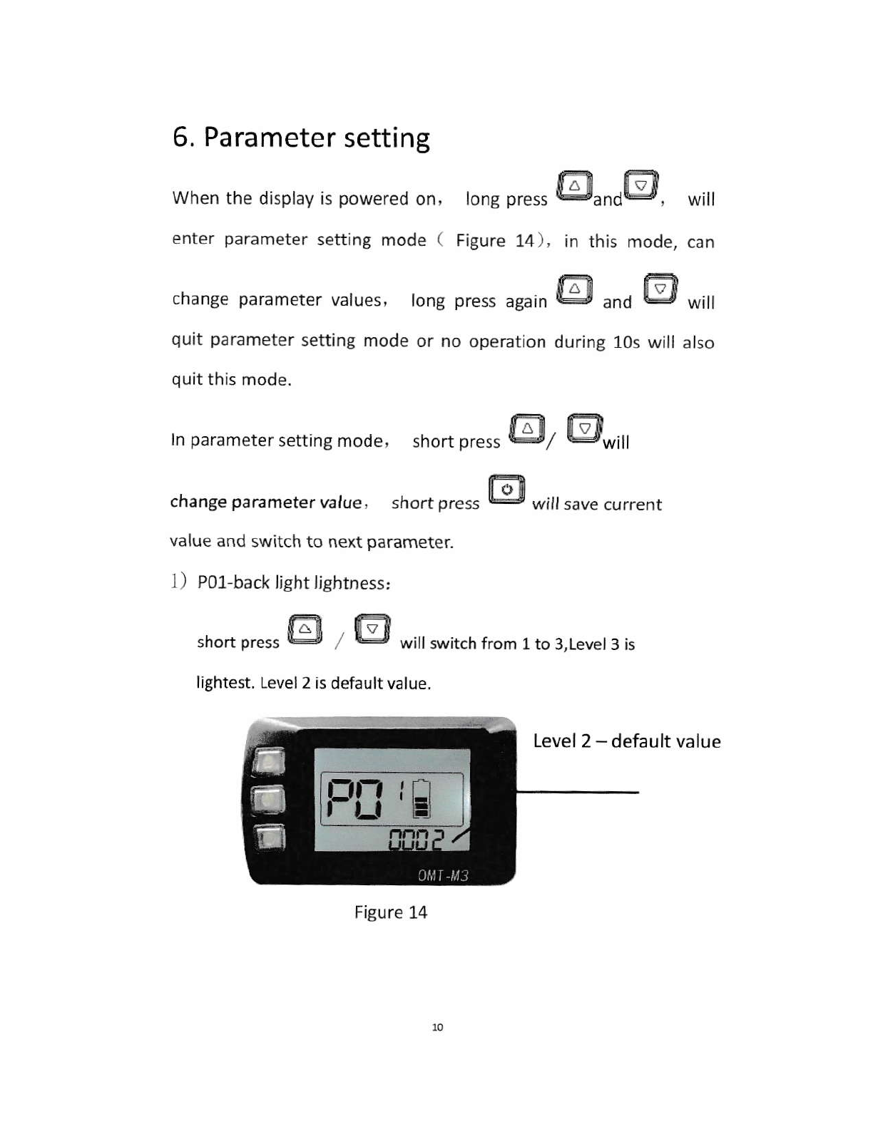
6. Parameter setting
when the display is powered on, long press @.nOB,
enter parameter setting mode ( Figure 14), in this mode,
change parameter values, long press "guin EI uno @ 'r,,,
quit parameter setting mode or no operation during 1Os will also
quit this mode.
shortpress El7 E},r,,,
In para meter setting mode,
change parameter value,
will
can
short press @ will save current
value and switch to next parameter
1) Pol-back light lightness:
short press tr! , Ex witt switch from 1to 3,Levet 3 is
lightest. Level 2 is default value.
Level 2 - defau lt value
Figure 1.4
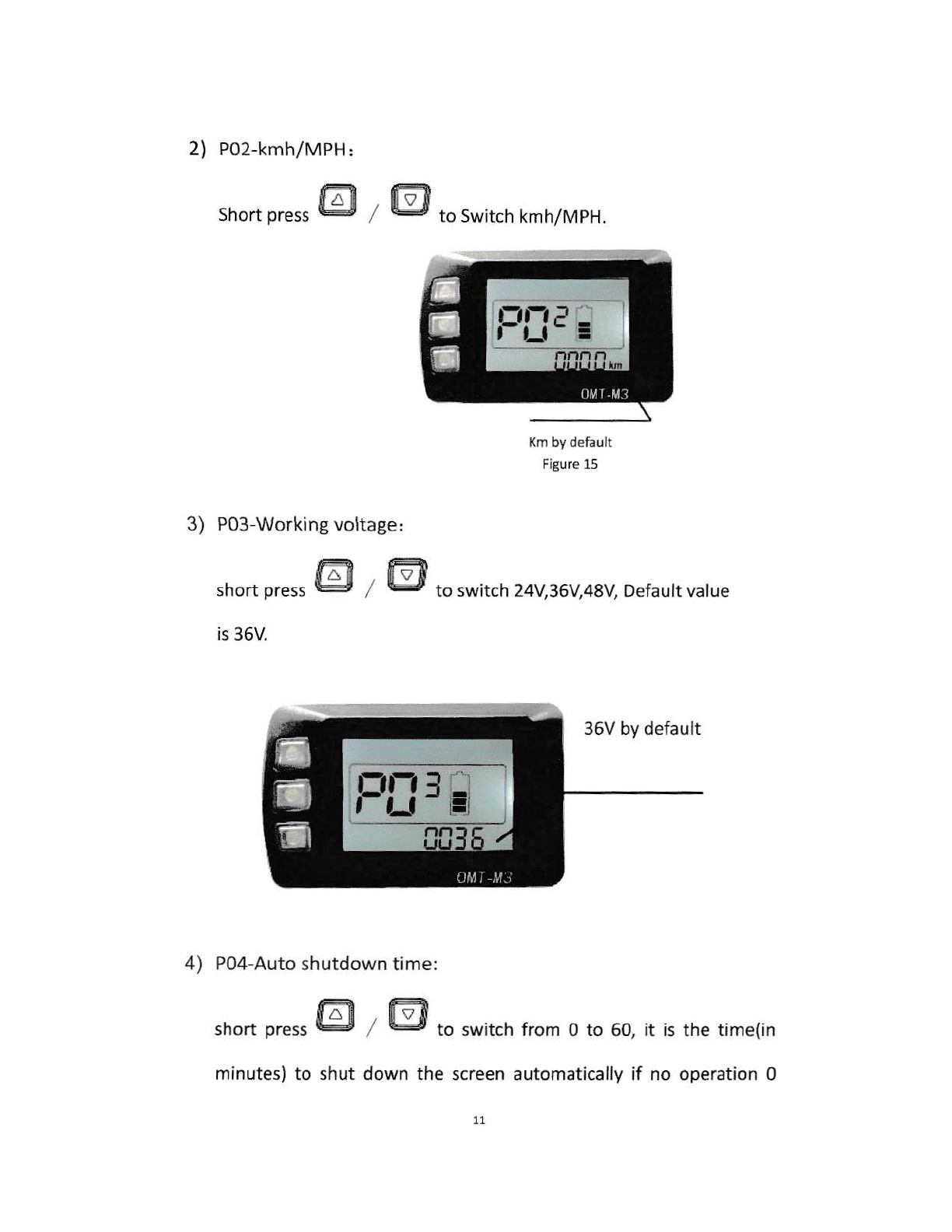
2) Po2-kmh/MPH:
shorr press trl , El to switch kmh/MpH.
Figure 15
3) P03 Working voltage:
short press El , El to switch 24V36V48V Default value
is 36V
4) Po4-Auto shutdown time:
short press E! , trl to switch from o to 60, it is the time(in
36V by default
minutes) to shut down the screen automatically if no operation 0
I
-)
FIl
rfr,I -
, tJ --i

means never shut down, Default value is 10 minutes
5) Pos-Number of Assist levels:
short press @ , El to switch wheetsize, in inch, step: 0.1
5minutes
0:
1:
2t
short press El , El to change tevet o->r.->2.
3 assist levels
5 assist levels
9 assist levels
6) P06-Wheel size selection:
P05=1
inch
L7
Fil.' E,
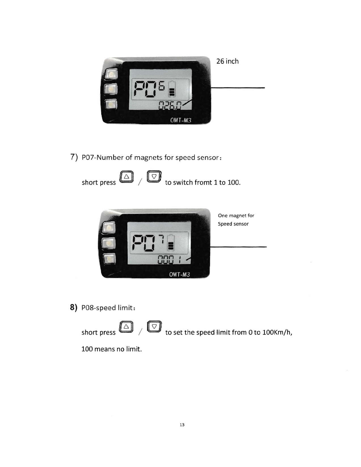
7) PO7-Number of magnets for speed sensor:
short press trl , trl to switch fromt 1to 1oo.
8) Po8-speed limit,
short press E! , trl to set the speed limit from o to 1ooKm/h,
100 means no limit.
13
r:,fi I -
,l)=

9) Po9-Non-zero speed start:
short press El , El to switch fromo to 1. o: zero speed
start,l:non-zero speed start.
10) P10-Driving mode selection;
short press E! , El to switch from o->1->2.
0: Assist mode (throttle does not work, only assist);
1: Electrical driving mode(only throttle works, assist does not work) ;
2: Both assist and Electrical driving mode(Not available if in zero speed
start and electrical driving mode);
FllE =
F,:t+

Driving mode:
11). P1l-assist sensitivity setting:
short press E , @ to switch from 1 to 24.
12) P12-assist starting power setting:
short press El , EI to switch from 0 to s.
ti_i _
l=
't-t I !
,,=
l5
Starting power of
assist
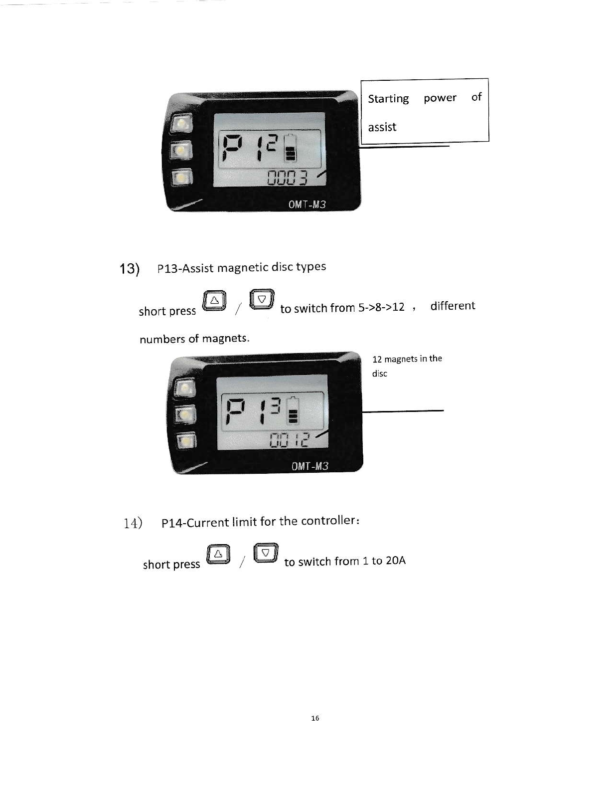
13) P13-Assist magnetic disc types
short press E ts to switch from 5->8->12 ' different
numbers of magneis
14) P14-Current limit for the controller:
short press E m to switch frorr 1to 2oA
r-1
g
Httj,=:: '
,t=
16
Other manuals for RF350
1
Table of contents
Other Merkava Bicycle manuals


