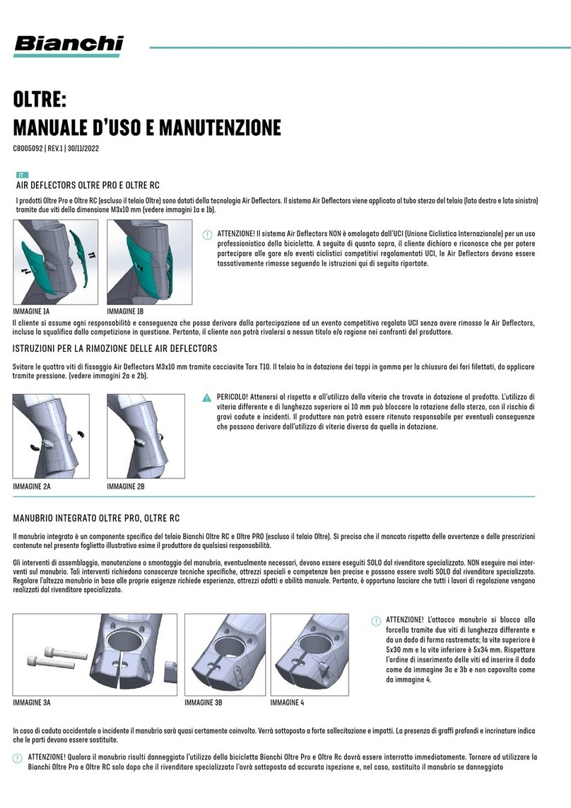
Bianchi E-ARCADEX Configuration guide

E-ARCADEX:
USER MANUAL SUPPLEMENT /
SUPPLEMENTO AL MANUALE UTENTE
C8005092-007 | 13 June 2023

2

3
INDEX
ENGLISH
ITALIANO
DEUTSCH
FRANÇAIS
ESPAÑOL
日本語
4
10
16
22
28
34

4
DECLARATION OF CONFORMITY
The manufacturer F.I.V.E. Bianchi S.p.A., located at Via delle Battaglie, 5 - 24047 Treviglio (BG), Italy, hereby declares that its products conform with
standards 2006/42/CE, 2014/30/UE, 2011/65/EU, 2014/53/EU, UNI EN 15194:2018 and ISO4210. The products also conform with the provisions of Art.
50 of the Italian Highway Code (Italian Legislative Decree no. 285 of 30 April 1992, as amended, and as amended by Art. 24/1 of Law no. 14 of 3
February 2003), as defined by Art. 2, paragraph 1, letter n) of the Agreement.
The complete list of product codes and the relative compliance information can be consulted under the “Declaration of Conformity” link at
www.bianchi.com/manuals/.
GENERAL SAFETY WARNINGS
Please pay close attention to the following symbols.
DANGER!
indicates a potential danger which may cause serious injury or death if not avoided.
WARNING!
indicates practices and conduct to be adopted for safe product use.
INFORMATION!
Indicates additional information on how to use the product.
WARNING!
Please note that failure to comply with the warnings and provisions contained in this data sheet exempts the manufacturer of any liability.
INTENDED USE
ASTM CATEGORY 2 – Cyclocross, gravel, crossbike and trekking bikes, including the relative Pedelec e-Bike pedal-assist versions.
Designed for use on surfaces as per Category 1 (artificially paved surfaces such as asphalt roads and cycleways) as well as
unpaved roads with gravel, sand or similar surfaces (e.g., forestry roads, dirt roads, paved hiking trails with few tree roots). The
tyres remain in constant contact with the ground or only lose contact briefly due to uneven ground. Drops are limited to 15 cm
(6”) or less.
FRAME AND FORK
Features: 100% carbon fibre frame and fork with tubing designed to add sportiness to the E-Arcadex.
Specifically designed to be compatible with the Bosch CX motor and integrated 500 Wh battery, mounted in a balanced position to optimise riding
agility.
Internal cable housing, casing and brake hoses.
The head tube is designed to house bearings from 1½”.
The fork is tapered with a 28.6 mm diameter seat post.
The frame and fork are equipped with an M12 thru-axle to attach the wheels. Front 12 x 100, rear 12 x 142.
The frame is compatible with bottle cages mounted to the seat post and the down tube.
Compatibility: The frame is only compatible with electronic and mechanical wireless shifting systems.
The frame is not compatible with electronic cable shifting systems.
The maximum tyre width is 45 mm without mudguards, 40 mm with mudguards.
The frame conforms to standard EN15194.
The maximum load capacity of the bike, system weight*, is indicated on the EPAC label, located in the motor housing unit.
* WARNING!
*System weight may vary depending on the set-up of each product. Please refer to the EPAC label on the product frame.
* WARNING!
The measurement refers to the actual size and not to the image on the cover.
EN

5
HEAD SET AND HANDLEBAR STEM AND BEND
The product uses a head set system for use with the ICR integrated cable routing system manufactured by FSA. Bearing diameters are 1½” for the
upper and lower parts.
The handlebar stem is compatible with seat posts measuring 28.6 mm in diameter and handlebar bends measuring 31.8 mm in diameter.
The height of this type of handlebar stem is adjustable by a specialist retailer. Due to the importance and complexity of this component, please
consult your retailer for stem adjustment and to fully understand the mechanisms and adjustment methods.
DANGER!
Always comply with the torque values specified on the stem. Incorrect tightening may cause
the component to malfunction or break, causing the rider to lose control and fall.
Never use this product with incomplete or incorrect assembly. This endangers not only the
rider but also other road users.
The gear/brake control levers are mounted on the handlebar using a clamp integrated into
the lever.
Pay close attention to the recommended positioning of the levers and respect the limits
indicated by the high grip zone (Image 1A).
Consult the lever product handbook for the correct torque. To preserve the integrity of the
handlebar bend, do not exceed the maximum torque of 10 Nm.
WARNING!
Turn the handlebar left and right. Do not use the bike if there is any evidence of abnormal steering (play in the steering or uneven resistance) or if
any cracks or signs of damage are evident.
In the event of an accident or fall, the handlebar will almost certainly be involved and will be subjected to high levels of stress and impact. In the
event of any deep scratches or cracks, replace the components.
INFORMATION!
New and innovative components and features are being developed all
the time.
To check compatibility with drive units other than those originally
installed on the Bianchi frame or to receive information and
instructions on specific components that may be required to install a
product or upgrade one, please contact your preferred Bianchi retailer.
A
B1
C
D
E
F
G
G1
H
I
X
Y
WB
E-Arcadex
SIZE A B1 C D E F G G1 H I X Y WB
XS 440 520 434 70 125 596 74.5° 70.5° 50 416 364 564 1020
SM 480 532 434 70 140 603 74° 70.5° 50 416 366 579 1028
MD 520 548 434 70 155 609 73.5° 71° 50 416 372 594 1034
LG 550 563 434 70 170 625 73.5° 71° 50 416 382 609 1049
XL 580 583 434 70 185 640 73° 71° 50 416 392 623 1064
Image 1A

6
WARNING!
If the handlebar is damaged, stop using the bike immediately.
Do not use the bike until a specialist retailer has conducted a full inspection and, if necessary, the handlebar has been replaced.
THRU-AXLE
WARNING!
Use caution and observe the following
warnings. Failure to comply with the warnings
and provisions contained in this data sheet
exempts the manufacturer from any liability.
Unlike quick-release systems, the thru-axles
provided with this model are screwed directly
onto the frame and fork dropouts using an M12
screw. The length of the thru-axle is specific
to this model and must be observed in order
to be able to assemble the wheels safely.
(Images 1B and 1C)
DANGER!
The use of a thru-axle other than the one
provided may result in the incorrect assembly
of the wheel and may compromise the
integrity of the frame and fork.
WARNING!
Always use the thru-axles provided with the model.
DANGER!
Incorrectly mounted wheels may result in falls and serious accidents. If in doubt, contact your specialist retailer.
DANGER!
Never exceed the maximum torque value indicated on the axles. Incorrect tightening may damage the frame and fork.
SEAT POST CLAMP/EXPANDER
WARNING!
Use caution and observe the following warnings. Failure to comply with
the warnings and provisions contained in this data sheet exempts the
manufacturer from any liability.
The clamp/expander system provided is designed specifically for use
with the e-Arcadex frame (Image 1D)
Without this component, it is not possible to lock the seat post in the
desired position.
To set the saddle height, loosen the M5 screws on the seat post clamp.
The recommended torque for the clamp/expander is 6 Nm.
INFORMATION!
For optimum grip and to eliminate slippage between the seat post and
the frame, place a layer of gripper paste on the part of the expander
that is in contact with the seat post. (the gripper paste is included
with the product). Image 1D
Image 1B Image 1C

7
DANGER!
Always comply with the torque levels specified on the seat post/expander
clamp. Failure to comply with the recommended torque levels may lead to
malfunction and cause the rider to fall.
SEAT POST
The product is compatible with 31.6 mm diameter seat posts
WARNING!
When removing the seat post never exceed the safety limit indicated on the
component. (Image 1E)
DANGER!
Exceeding the limit may cause the component to malfunction or break,
causing the rider to lose control and fall.
BATTERY COVER AND REMOVAL
To assemble the battery cover, push the upper part of the cover to set it into the frame (Image 1F). Next, tighten the screw located on the cover to
fix it to the frame (Image 1G).
The screw can be tightened by hand, but a screwdriver may be useful.
To remove the battery cover, loosen the screw entirely and lift off the cover.
Image 1F Image 1G
WARNING!
Do not pull or tug on the cover. Failure to fully unscrew the screw may result in damage to the locking mechanism.
Stop tightening the screw if there is resistance and restart the process from the beginning, aiming to position the cover closer to the frame.
BATTERY LOCK
The battery is secured to the bike with a lock. To remove, unlock it by turning the key provided (clockwise). To install the battery, turn the key
clockwise, push the battery in and release the key. Turn the key anti-clockwise to lock and remove the key. Images 1H and 1J
The product is provided with two keys identified with a code on the tag (see image). Please make a note of this code. In the event that both keys
are lost, a duplicate key can be requested by providing the code directly to the supplier ABUS (www.abus.com).
Image 1E

8
CARGO RACKS, PANNIER RACKS AND MUDGUARDS
The pannier racks and mudguards are designed to be assembled as a single component, with the pannier rack mounted directly onto the rear
mudguard. The pannier rack provided with the product is rated to a maximum load of 15 kg (Image 1K) in this combination only.
WARNING!
The maximum load of 15 kg is only guaranteed if assembled
using the mudguards provided.
Side panniers can be mounted using flexible hook and
loop closure and/or strap systems. There is no specific
recommended pannier fixing system.
WARNING!
The cargo rack cannot be assembled without the
mudguards provided. The 15 kg maximum load is only
and exclusively guaranteed if the two components are
assembled together.
The mudguards provided have a cross-section of 46 mm
and are compatible with tyres up to a maximum of 40 mm.
LIGHT SYSTEM
The bike has front and rear lights. Both lights can be switched on or off from the remote control dashboard of the remote control of the pedal-assist
system. The front light is mounted on the handlebar, while the rear light is integrated into the rear mudguard.
ADDITIONAL TECHNICAL INFORMATION
Not all components available on the market are compatible with the E-Arcadex frame.
Not all devices available on the market, such as child seats, stabilisers and bike cargo trailers, are compatible with the E-Arcadex frame.
Only the components specified on the product have been tested by Bianchi. Please check design and compatibility before purchasing new products.
WARNING!
Before purchasing and assembling products and/or devices, always check that the bike and the components are fully compatible. Bianchi does not
provide any guarantee or assume any responsibility in the case of product damage.
Image 1J
Image 1K
Image 1H

9

10
DICHIARAZIONE DI CONFORMITÀ
Il produttore F.I.V.E. Bianchi S.p.A. sito in Via delle Battaglie, 5 - 24047 Treviglio (BG), dichiara che i suoi prodotti sono conformi alle corrispondenti
normativa 2006/42/CE, 2014/30/UE, 2011/65/EU, 2014/53/EU, UNI EN 15194:2018 e ISO4210. I prodotti rispondono inoltre a quanto disposto dall’art. 50
del Codice della strada (decreto legislativo 30 aprile 1992 n. 285 e successive modificazioni, così come innovato dall’art. 24/1 della legge 3 febbraio
2003 n. 14) così come definiti all’art. 2, comma 1, lettera n dell’Accordo.
Al seguente indirizzo web www.bianchi.com/manuals/ alla voce dichiarazione di conformità è possibile consultare l’elenco completo dei codici
prodotto e le relative compatibilità.
AVVERTENZE DI SICUREZZA GENERALI
Prestare particolare attenzione ai seguenti simboli.
PERICOLO!
segnala un possibile pericolo, che se non evitato può comportare la morte o gravi lesioni.
ATTENZIONE!
segnala norme e comportamenti da apprendere per conoscere e utilizzare il prodotto in sicurezza.
INFORMAZIONE/NOTA!
segnala informazioni aggiuntive utili all’uso del prodotto.
ATTENZIONE!
Si precisa che il mancato rispetto delle avvertenze e delle prescrizioni contenute nel presente foglietto illustrativo esime il produttore da qualsiasi
responsabilità.
DESTINAZIONE D’USO
ASTM CATEGORIA 2 – Biciclette da ciclocross, gravel, crossbike e da trekking comprese le relative versioni a pedalata assistita
e-Bike Pedelec.
Destinate ad essere utilizzate su superfici come da categoria 1 (superfici pavimentate artificialmente quali strade asfaltate e
piste ciclabili) oltre a vie ricoperte di ghiaia, sabbia o materiali analoghi (ad es. strade forestali, sterrati, sentieri escursionistici
pavimentati con una presenza ridotta di radici). Le ruote sono costantemente a contatto con il suolo o lo perdono solamente a
causa di asperità del terreno per brevi istanti sono ammessi salti non superiori ai 15 cm (6 pollici).
TELAIO E FORCELLA
Caratteristiche: Telaio e forcella sono realizzati interamente in fibra di carbonio, con linee dei tubi definite e studiate per conferire sportività alla
E-Arcadex.
Specifico design per accogliere il motore Bosch CX e la batteria integrata da 500Wh posizionati in modo equilibrato per consentire la massima
agilità di guida.
L’alloggiamento dei cavi, delle guaine e dei tubi idraulici è interno al telaio.
Il tubo sterzo del telaio è progettato per alloggiare direttamente cuscinetti da 1”1/2.
La forcella è di tipo conica (tapered) con il tubo cannotto dal diametro di 28.6 mm.
Il telaio e la forcella adottano perni passanti da M12 per il fissaggio ruote. Anteriore 12x100, posteriore 12x142.
Il telaio è predisposto per l’assemblaggio di porta borraccia al tubo sella e al tubo inclinato.
Compatibilità: Il telaio è compatibile solo con trasmissioni di tipo meccanico o elettronico wireless.
Il telaio non è compatibile con trasmissione elettronica di tipo cablata.
La sezione massima assemblabile degli pneumatici è 45mm senza parafanghi, 40mm con parafanghi assemblati.
Il telaio è omologato secondo la norma EN15194.
La portata massima della bici, peso sistema*, è riportata nell’etichetta EPAC, posizionata nella zona scatola motore.
* ATTENZIONE!
*Il peso sistema può variare in funzione dell’allestimento di ogni prodotto, fare riferimento all’etichetta EPAC presente sul telaio del prodotto.
* ATTENZIONE!
La misura si riferisce ad una dimensione reale e non a quanto indicato sulla copertura.
IT

11
INFORMAZIONE/NOTA!
Sempre più frequentemente componenti e caratteristiche totalmente
nuove e innovative vengono ideate.
Per conoscere la compatibilità con le linee di componenti-trasmissioni
(drive-unit) diverse da quelle assemblate in origine sul telaio Bianchi
o per ricevere informazioni e indicazioni di eventuali componenti
specifici necessari per il montaggio del prodotto o per il suo upgrade, si
prega di contattare il rivenditore specializzato Bianchi.
A
B1
C
D
E
F
G
G1
H
I
X
Y
WB
E-Arcadex
SIZE A B1 C D E F G G1 H I X Y WB
XS 440 520 434 70 125 596 74.5° 70.5° 50 416 364 564 1020
SM 480 532 434 70 140 603 74° 70.5° 50 416 366 579 1028
MD 520 548 434 70 155 609 73.5° 71° 50 416 372 594 1034
LG 550 563 434 70 170 625 73.5° 71° 50 416 382 609 1049
XL 580 583 434 70 185 640 73° 71° 50 416 392 623 1064
ATTACCO, PIEGA MANUBRIO E SERIE STERZO
Il prodotto utilizza un sistema di serie sterzo per il passaggio guaine interne del fornitore FSA tipologia ICR, i cuscinetti hanno dimensione da 1”1/2
sia per la parte superiore che inferiore.
L’ attacco manubrio in dotazione è compatibile con il tubo cannotto forcella dal diametro di 28.6 mm e con pieghe manubrio dal diametro 31.8mm.
La regolazione in altezza di questa tipologia di attacco manubrio può essere eseguita, in origine, dal rivenditore specializzato. In considerazione
della rilevanza e complessità di questa specifica componentistica, invitiamo sempre a consultare il rivenditore di fiducia per la regolazione
dell’attacco manubrio e per comprendere a fondo i meccanismi e le metodologie di regolazione.
PERICOLO!
Attenersi alle coppie di serraggio specificate sull’attacco manubrio. Serraggi non
correttamente eseguiti possono causare il malfunzionamento o la rottura del componente con
conseguente perdita del controllo del veicolo e cadute!
Non utilizzare mai il prodotto qualora i lavori di assemblaggio siano incompleti o svolti in modo
scorretto. In questo modo, infatti, si mette in pericolo se stessi e gli altri mezzi di circolazione.
Le leve comando cambio/freno si fissano alla piega manubrio mediante fascetta integrata
alla leva comando.
Prestare molta attenzione al corretto posizionamento delle leve, rispettare la posizione di
fissaggio entro i limiti indicati dalla zona ad alto grip (Immagine 1A).
Consultare lo specifico manuale del produttore delle leve comando cambio/freno per conoscere la coppia di serraggio da applicare. Per preservare
l’integrità della piega manubrio non superare la coppia massima di 10 Nm.
ATTENZIONE!
Ruotare il manubrio verso sinistra e verso destra, non utilizzare la bicicletta se si nota un comportamento anomalo dello sterzo (gioco nello sterzo
o resistenza non uniforme) o se sono evidenti delle cricche e crepe.
In caso di caduta o incidente il manubrio sarà quasi certamente coinvolto. Verrà sottoposto a forte sollecitazione e impatti. La presenza di graffi
profondi e incrinature indica che le parti devono essere sostituite.
Immagine 1A

12
ATTENZIONE!
Qualora il manubrio risulti danneggiato l’utilizzo della bicicletta dovrà essere interrotto immediatamente.
Tornare ad utilizzare il prodotto solo dopo che il rivenditore specializzato l’avrà sottoposta ad accurata ispezione e, nel caso, sostituito il manubrio se
danneggiato.
PERNI PASSANTI “THRU-AXLE”
ATTENZIONE!
Si prega di fare molta attenzione e di rispettare
le avvertenze che seguono. Il mancato rispetto
delle seguenti avvertenze e delle prescrizioni
contenute nel presente foglietto illustrativo
esime il produttore da qualsiasi responsabilità.
I perni passanti forniti in dotazione,
diversamente dai bloccaggi rapidi “quick
release”, si avvitano direttamente sui forcellini
del telaio e della forcella, attraverso una
filettatura M12. I perni “thru-axle” hanno
una lunghezza specifica per questo modello,
misura da rispettare per poter assemblare le
ruote in sicurezza. (Immagini 1B e 1C)
PERICOLO!
L’utilizzo di un perno diverso da quello in dotazione può implicare un assemblaggio scorretto della ruota e compromettere l’integrità del telaio e
forcella.
ATTENZIONE!
Attenersi al rispetto e all’utilizzo dei perni passanti che trovate in dotazione al prodotto.
PERICOLO!
Le ruote montate scorrettamente possono causare cadute e gravi incidenti. In caso di dubbi contattare il proprio rivenditore specializzato.
PERICOLO!
Non superare mai la coppia massima di serraggio indicata sui perni. Serraggi non correttamente eseguiti possono danneggiare il telaio e la forcella.
BLOCCHETTO CHIUSURA REGGISELLA/EXPANDER
ATTENZIONE!
Si prega di fare molta attenzione e di rispettare le avvertenze che
seguono. Il mancato rispetto delle seguenti avvertenze e delle
prescrizioni contenute nel presente foglietto illustrativo esime il
produttore da qualsiasi responsabilità.
Il sistema di serraggio/expander in dotazione è un componente
specifico per il telaio e-Arcadex (Immagine 1D)
Senza di esso non è possibile bloccare il cannotto reggisella nella
posizione desiderata.
Per impostare l’altezza sella è necessario allentare la vite M5 del
bloccaggio reggisella.
La coppia di chiusura raccomandata del sistema di serraggio/expander
è di 6 Nm.
INFORMAZIONE/NOTA!
Per garantire un maggiore grip ed un migliore fissaggio del tubo
reggisella nel telaio, si consiglia di porre un velo di pasta grippante
sulla parte dell’espander a contatto con il reggisella. (la pasta
grippante è in dotazione al prodotto).
Immagine 1D
Immagine 1B Immagine 1C

13
PERICOLO!
Attenersi alla coppia di serraggio specificata sul blocchetto chiusura/
expander. Serraggi non correttamente eseguiti possono causare il
malfunzionamento del componente e di conseguenza cadute.
CANNOTTO REGGISELLA
Il prodotto è compatibile con cannotto reggisella con diametro 31,6 mm
ATTENZIONE!
Nell’estrarre il cannotto reggisella non superare il limite di sicurezza
contrassegnato sul cannotto stesso. (Immagine 1E)
PERICOLO!
Superare il limite indicato può causare o la rottura del componente con
conseguente perdita del controllo del veicolo e cadute
COVER BATTERIA E RIMOZIONE
Per assemblare la cover batteria, è necessario spingere in profondità la parte superiore della cover nel telaio (Immagine 1F). Successivamente è
necessario avvitare la vite che si trova nella cover dentro l’apposito supporto (Immagine 1G).
È sufficiente avvitarla a mano, ma ci si può aiutare con un cacciavite.
Per rimuovere la cover batteria, bisogna svitare completamente la vite di chiusura e sfilare la cover.
Immagine 1F Immagine 1G
ATTENZIONE!
Non tirare o strattonare la cover. Se la vite di fissaggio non è completamente allentata, c’è il rischio di danneggiare il meccanismo di chiusura.
Interrompere il serraggio della vite se si incontra resistenza durante la chiusura, ripetere l’operazione dall’inizio cercando di inserire la cover più
in profondità.
LUCCHETTO BATTERIA
La batteria è assicurata alla bicicletta tramite un lucchetto. Per la rimozione è quindi necessario “aprire” il lucchetto utilizzando la chiave in
dotazione (rotazione oraria chiave) viceversa per il montaggio della batteria è necessario per prima cosa ruotare in senso orario la chiave lucchetto,
spingere la batteria e rilasciare la chiave. Successivamente è possibile chiudere il lucchetto e sfilare la chiave (rotazione antioraria della chiave).
Immagini 1H e 1J
Immagine 1E

14
PORTAPACCHI, PORTABORSE E PARAFANGHI
Il portapacchi ed i parafanghi sono studiati per essere assemblati come un unico componente, il portapacchi è fissato direttamente al parafango
posteriore. Solo in questa combinazione il portapacchi in dotazione al prodotto è omologato per un carico massimo di 15kg (Immagine 1K)
ATTENZIONE!
Il carico massimo di 15Kg è assicurato solo se assemblato
con i parafanghi che trovate in dotazione.
È possibile assemblare borse laterali con sistemi di
aggancio flessibili tipo velcro e/o fascette. Non è previsto
un particolare sistema di fissaggio per le borse.
ATTENZIONE!
Il portapacchi non può essere assemblato senza i
parafanghi in dotazione, il carico massimo di 15 kg sono
certificati solo ed esclusivamente se assemblati insieme.
I parafanghi in dotazione hanno una sezione di 46mm,
misura compatibile con pneumatici di misura massima 40
mm, che risulta essere la misura massima assemblabile.
Immagine 1J
Immagine 1K
Immagine 1H
Sono fornite in dotazione due chiavi identificate da un codice presente sulla targhetta (vedi immagine) è importante annotare questo codice perché
qualora si dovessero smarrire entrambe le chiavi, è possibile richiedere un duplicato della chiave fornendo il codice direttamente al fornitore ABUS
(www.abus.com)

15
IMPIANTO LUCI
Sono presenti le luci anteriore e posteriore. Entrambe possono essere accese o spente dal comando remoto del sistema a pedalata assistita. La
posizione della luce anteriore è alla piega manubrio, quella posteriore è integrata nel parafango posteriore.
INFORMAZIONI TECNICHE AGGIUNTIVE
Non tutti i componenti presenti nel mercato sono compatibili con il telaio E-Arcadex.
Non tutti i dispositivi, come seggiolini porta bimbo, rulli d’allenamento e carrelli per bici/trailer, presenti nel mercato sono compatibili con il telaio
E-Arcadex.
Solo i componenti specificati sul prodotto sono stati testati da Bianchi. Prima dell’acquisto di nuovi componenti controllate sempre i disegni e le
tolleranze.
ATTENZIONE!
Prima dell’acquisto e assemblaggio di componenti e/o dispositivi è obbligatorio controllare e accertarsi che bicicletta e componente siano
perfettamente compatibili. Bianchi non fornisce alcuna garanzia e non si assume alcuna responsabilità in caso di danno al prodotto.

16
KONFORMITÄTSERKLÄRUNG
Der Hersteller F.I.V.E. Bianchi S.p.A. mit Sitz in Via delle Battaglie, 5 - 24047 Treviglio (BG), erklärt, dass seine Produkte den entsprechenden Normen 2006/42/
EG, 2014/30/EU, 2011/65/EU, 2014/53/EU, UNI EN 15194:2018 und ISO4210 entsprechen. Die Produkte entsprechen auch den Bestimmungen von Artikel 50
der italienischen Straßenverkehrsordnung (Gesetzesverordnung Nr. 285 vom 30. April 1992 und nachfolgende Änderungen, geändert durch Artikel 24/1 des
Gesetzes Nr. 14 vom 3. Februar 2003), wie in Artikel 2 Absatz 1 Buchstabe n des Vertrags definiert.
Auf der Website https://www.bianchi.com/manuals/ finden Sie unter dem Link Konformitätserklärung die vollständige Liste der Artikelnummern mit Angabe
der jeweiligen angewandten Normen.
ALLGEMEINE SICHERHEITSHINWEISE
Bitte achten Sie besonders auf die folgenden Symbole.
GEFAHR!
weist auf eine mögliche Gefahr hin, die, wenn sie nicht vermieden wird, zum Tod oder zu schweren Verletzungen führen kann.
ACHTUNG!
weist auf Regeln und Verhaltensweisen hin, die zu erlernen sind, um das Produkt kennenzulernen und sicher zu verwenden.
INFORMATION/HINWEIS!
weist auf zusätzliche Informationen hin, die für die Verwendung des Produkts nützlich sind.
ACHTUNG!
Es wird darauf hingewiesen, dass die Nichtbeachtung der in dieser Gebrauchsinformation enthaltenen Warnhinweise und Vorschriften den Hersteller von
jeglicher Haftung befreit.
VERWENDUNGSZWECK
ASTM KATEGORIE 2 – Cyclocross-, Gravel-, Crossbike- und Trekking-Fahrräder einschließlich ihrer Pedelec- und E-Bike-Versionen.
Zur Verwendung auf Flächen der Kategorie 1 (künstlich befestigte Flächen wie asphaltierte Straßen und Radwege) sowie mit Kies, Sand
oder ähnlichen Materialien bedeckte Wege (z. B. Forststraßen, Feldwege, befestigte Wanderwege mit geringem Wurzelanteil). Die Räder
sind ständig in Kontakt mit dem Boden bzw. verlieren diesen nur durch Bodenunebenheiten für kurze Momente; Sprünge sind bis maximal
15 cm zulässig.
RAHMEN UND GABEL
Eigenschaften: Der Rahmen und die Gabel sind komplett aus Kohlefaser gefertigt, mit definierten Rohrlinien, die dem E-Arcadex Sportlichkeit verleihen.
Spezielles Design zur Aufnahme des Bosch CX Motors und des integrierten 500-Wh-Akkus, der ausgewogen positioniert ist, um maximale Wendigkeit zu
ermöglichen.
Die Kabel, Mäntel und Hydraulikschläuche sind im Inneren des Rahmens untergebracht.
Das Steuerrohr des Rahmens ist für die direkte Aufnahme von 1 1/2“-Lagern ausgelegt.
Die Gabel ist konisch geformt (tapered) und hat einen Schaftdurchmesser von 28,6 mm.
Der Rahmen und die Gabel verfügen über M12-Steckachsen für die Radbefestigung. Vorn 12x100, hinten 12x142.
Am Sitzrohr und am Unterrohr des Rahmens können Flaschenhalter montiert werden.
Kompatibilität: Der Rahmen ist nur mit mechanischen oder drahtlosen elektronischen Übertragungsmethoden kompatibel.
Der Rahmen ist nicht mit elektronischen Übertragungsmethoden per Kabel kompatibel.
Der größte montierbare Reifenquerschnitt beträgt 45 mm ohne Schutzbleche, 40 mm mit montierten Schutzblechen.
Der Rahmen ist nach EN 15194 zugelassen.
Die maximale Tragfähigkeit des Fahrrads, das Systemgewicht*, finden Sie auf dem EPAC-Etikett, das sich im Bereich des Motorgehäuses befindet.
* ACHTUNG!
*Das Systemgewicht kann je nach Ausstattung des jeweiligen Produkts variieren, bitte beachten Sie das EPAC-Etikett auf dem Produktrahmen.
* ACHTUNG!
Die Maße beziehen sich auf die tatsächliche Größe und nicht auf die Angabe auf dem Reifen.
DE

17
INFORMATION/HINWEIS!
Immer häufiger werden völlig neue und innovative Komponenten und
Merkmale entwickelt.
Um sich über die Kompatibilität mit anderen als den ursprünglich am
Bianchi Rahmen montierten Antriebskomponenten zu informieren, oder um
Informationen und Angaben zu den für die Montage oder Aufrüstung des
Produkts erforderlichen spezifischen Komponenten zu erhalten, wenden
Sie sich bitte an Ihren Bianchi Fachhändler.
A
B1
C
D
E
F
G
G1
H
I
X
Y
WB
E-Arcadex
SIZE A B1 C D E F G G1 H I X Y WB
XS 440 520 434 70 125 596 74.5° 70.5° 50 416 364 564 1020
SM 480 532 434 70 140 603 74° 70.5° 50 416 366 579 1028
MD 520 548 434 70 155 609 73.5° 71° 50 416 372 594 1034
LG 550 563 434 70 170 625 73.5° 71° 50 416 382 609 1049
XL 580 583 434 70 185 640 73° 71° 50 416 392 623 1064
VORBAU, LENKERBÜGEL UND STEUERSATZ
Das Produkt verwendet ein Steuersatzsystem für die Innendurchführung der Mäntel des Zulieferers FSA Typ ICR, die Lager haben eine Größe von 1“1/2
sowohl oben als auch unten.
Der mitgelieferte Vorbau ist kompatibel mit einem Gabelschaft mit 28,6 mm Durchmesser und Lenkerbügeln mit 31,8 mm Durchmesser.
Die Höheneinstellung dieses Vorbautyps kann zunächst von Ihrem Fachhändler vorgenommen werden. In Anbetracht der Bedeutung und Komplexität dieses
spezifischen Bauteils empfehlen wir Ihnen immer, sich an Ihren Fachhändler zu wenden, um die Einstellung des Vorbaus vornehmen zu lassen und die
Mechanismen und Methoden der Einstellung genau zu verstehen.
GEFAHR!
Beachten Sie die auf dem Vorbau angegebenen Anzugsmomente. Ein nicht korrekt ausgeführter
Anzug kann zu Fehlfunktionen oder zum Bruch des Bauteils führen, was zum Verlust der Kontrolle
über das Fahrrad und zu Stürzen führen kann!
Benutzen Sie das Produkt niemals, wenn die Montagearbeiten noch nicht vollständig oder nicht
korrekt ausgeführt wurden. Damit gefährden Sie sich und andere Verkehrsteilnehmer.
Die Schalt-/Bremshebel werden mit einer in den Schalthebel integrierten Schelle am Lenker
befestigt.
Achten Sie auf die korrekte Positionierung der Hebel und vermeiden Sie eine Befestigung außerhalb
des Bereichs mit hohem Grip (Abbildung 1A).
Das anzuwendende Anzugsmoment entnehmen Sie bitte dem Handbuch des Herstellers der
Schalt-/Bremshebel. Um den Lenkerbügel nicht zu beschädigen, darf das maximale Anzugsmoment
von 10 Nm nicht überschritten werden.
ACHTUNG!
Drehen Sie den Lenker nach links und rechts, benutzen Sie das Fahrrad nicht, wenn Sie ein abnormales Lenkverhalten feststellen (Spiel in der Lenkung oder
ungleichmäßiger Widerstand) oder wenn Risse und Sprünge zu sehen sind.
Im Falle eines Sturzes oder Unfalls wird der Lenker mit ziemlicher Sicherheit beteiligt sein. Er wird starken Belastungen und Aufprallbeanspruchungen
ausgesetzt sein. Tiefe Kratzer und Risse deuten darauf hin, dass die Teile ersetzt werden müssen.
Abbildung 1A

18
ACHTUNG!
Sollte der Lenker beschädigt sein, darf das Fahrrad ab sofort nicht mehr benutzt werden.
Verwenden Sie das Produkt erst wieder, nachdem der Fachhändler es gründlich überprüft und gegebenenfalls den beschädigten Lenker ersetzt hat.
THRU-AXLE-STECKACHSEN
ACHTUNG!
Bitte gehen Sie sehr sorgfältig vor und
beachten Sie die folgenden Warnhinweise. Die
Nichtbeachtung der folgenden Warnhinweise
und der in dieser Gebrauchsinformation
enthaltenen Vorschriften befreit den Hersteller
von jeglicher Haftung.
Die mitgelieferten Steckachsen werden im
Gegensatz zu Schnellspannern über ein M12-
Gewinde direkt an die Ausfallenden von Rahmen
und Gabel geschraubt. Die Steckachsen haben
bei diesem Modell eine bestimmte Länge, die
eingehalten werden muss, um die Räder sicher
montieren zu können. (Bild 1B und 1C)
GEFAHR!
Die Verwendung einer anderen als der
mitgelieferten Achse kann zu einer fehlerhaften
Montage des Rades und zur Beschädigung von
Rahmen und Gabel führen.
ACHTUNG!
Verwenden Sie die mitgelieferten Steckachsen und beachten Sie die entsprechenden Vorschriften.
GEFAHR!
Nicht ordnungsgemäß montierte Räder können zu Stürzen und schweren Unfällen führen. Wenden Sie sich bei Fragen an Ihren Fachhändler.
GEFAHR!
Überschreiten Sie niemals das auf den Achsen angegebene maximale Anzugsdrehmoment. Durch einen nicht korrekt ausgeführten Anzug können Rahmen
und Gabel beschädigt werden.
KLEMMBLOCK FÜR SATTELSTÜTZE/EXPANDER
ACHTUNG!
Bitte gehen Sie sehr sorgfältig vor und beachten Sie die folgenden
Warnhinweise. Die Nichtbeachtung der folgenden Warnhinweise und
der in dieser Gebrauchsinformation enthaltenen Vorschriften befreit den
Hersteller von jeglicher Haftung.
Das mitgelieferte Klemm-/Expandersystem ist ein spezifisches Bauteil für
den e-Arcadex Rahmen (Bild 1D).
Ohne dieses ist es nicht möglich, die Sattelstütze in der gewünschten
Position zu arretieren.
Um die Sattelhöhe einzustellen, lösen Sie die M5-Schraube der
Sattelstützenklemme.
Das empfohlene Anzugsdrehmoment für das Klemm-/Expander-System
beträgt 6 Nm.
INFORMATION/HINWEIS!
Um einen besseren Halt und eine bessere Fixierung der Sattelstütze im
Rahmen zu gewährleisten, empfiehlt es sich, den Teil des Expanders,
der mit der Sattelstütze in Berührung kommt, mit etwas Montagepaste
zu bestreichen, um die Haftung zu erhöhen. (die Montagepaste ist im
Lieferumfang des Produkts enthalten).
Bild 1D
Bild 1B Bild 1C

19
GEFAHR!
Halten Sie das auf dem Klemmblock/Expander angegebene Anzugsdrehmoment
ein. Ein nicht korrekt ausgeführter Anzug kann zu Fehlfunktionen des Bauteils
und in der Folge zu Stürzen führen.
SATTELSTÜTZE
Das Produkt ist kompatibel mit Sattelstützen mit 31,6 mm Durchmesser.
ACHTUNG!
Die Sattelstütze nicht weiter als bis zur an der Sattelstütze markierten
Sicherheitslinie herausziehen. (Bild 1E)
GEFAHR!
Das Herausziehen über die angegebene Grenze hinaus kann zu Fehlfunktionen
oder zum Bruch des Bauteils führen, was zum Verlust der Kontrolle über das
Fahrrad und zu Stürzen führen kann!
BATTERIEABDECKUNG UND ENTFERNUNG
Um die Batterieabdeckung zu montieren, muss der obere Teil der Abdeckung tief in den Rahmen gedrückt werden (Abbildung 1F). Anschließend muss die
Schraube in der Abdeckung in die entsprechende Aufnahme geschraubt werden (Bild 1G).
Es reicht aus, sie von Hand einzuschrauben, aber Sie können auch einen Schraubenzieher zu Hilfe nehmen.
Abbildung 1F Bild 1G
Um die Batterieabdeckung zu entfernen, muss die Verschlussschraube ganz herausgedreht und die Abdeckung herausgezogen werden.
ACHTUNG!
Ziehen oder zerren Sie nicht an der Abdeckung. Wenn die Befestigungsschraube nicht vollständig gelöst wird, besteht die Gefahr, dass der
Verschlussmechanismus beschädigt wird.
Ziehen Sie die Schraube nicht weiter an, wenn Sie beim Schließen auf Widerstand stoßen, sondern wiederholen Sie den Vorgang von Anfang an und
versuchen Sie, die Abdeckung tiefer einzuschieben.
Bild 1E

20
GEPÄCKTRÄGER, TASCHENHALTER UND SCHUTZBLECHE
Der Gepäckträger und die Schutzbleche sind so konzipiert, dass sie als ein einziges Bauteil montiert werden können, wobei der Gepäckträger direkt am
hinteren Schutzblech befestigt wird. Nur in dieser Kombination ist der mitgelieferte Gepäckträger für eine maximale Belastung von 15 kg zugelassen
(Bild 1K).
ACHTUNG!
Die maximale Belastung von 15 kg ist nur bei Montage mit den
mitgelieferten Schutzblechen gewährleistet.
DieSeitentaschenkönnenmitflexiblenBefestigungssystemen
wie Klettverschlüssen und/oder Schellen montiert werden.
Ein besonderes Befestigungssystem für Taschen ist nicht
vorgesehen.
ACHTUNG!
Der Gepäckträger darf nicht ohne die mitgelieferten
Schutzbleche montiert werden, die maximale Belastung von
15 kg ist nur zugelassen, wenn sie zusammen montiert sind.
Die mitgelieferten Schutzbleche haben einen Querschnitt von
46 mm, der mit Reifen bis zu einer maximalen Größe von 40
mm kompatibel ist.
Bild 1J
Bild 1K
Bild 1H
BATTERIESCHLOSS
Die Batterie wird mit einem Schloss am Fahrrad gesichert. Um die Batterie zu entfernen, muss das Schloss daher mit dem mitgelieferten Schlüssel
„geöffnet“ werden (Schlüssel im Uhrzeigersinn drehen), umgekehrt muss zum Einsetzen der Batterie zunächst der Schlüssel im Uhrzeigersinn gedreht,
die Batterie hineingedrückt und der Schlüssel dann losgelassen werden. Das Schloss kann dann abgeschlossen und der Schlüssel abgezogen werden
(Schlüssel gegen den Uhrzeigersinn drehen). Bild 1H und 1J
Im Lieferumfang sind zwei Schlüssel enthalten, die durch einen Code auf dem Typenschild gekennzeichnet sind (siehe Bild). Es ist wichtig, sich diesen Code
zu notieren, denn sollten Sie beide Schlüssel verlieren, können Sie unter Angabe des Codes direkt beim Hersteller ABUS einen Nachschlüssel anfordern
(www.abus.com)
Table of contents
Languages:
Other Bianchi Bicycle manuals
