EN
page 5
INSTALLER SECTION
code 10799
image 1
WARNING: check very carefully if the “ground connection” of the machine, is
properly sized and fully effi
cient, and that not too many units are connected on
it. An undersized or poor “ground connection” might lead to corrosion and/or
pitting effect on the stainless steel plates, even to perforation.
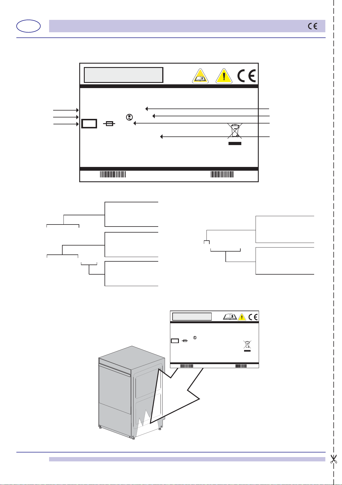
On the back of the appliance there is a terminal marked with the symbol , which
is provided for equipotential connection between different appliances (see electrical
safety standards).
Feed cable: the retailer - importer - installer must ensure that the feed cable
complies with the cable insulation category of the workplace, in conformity with
current Technical Standards.
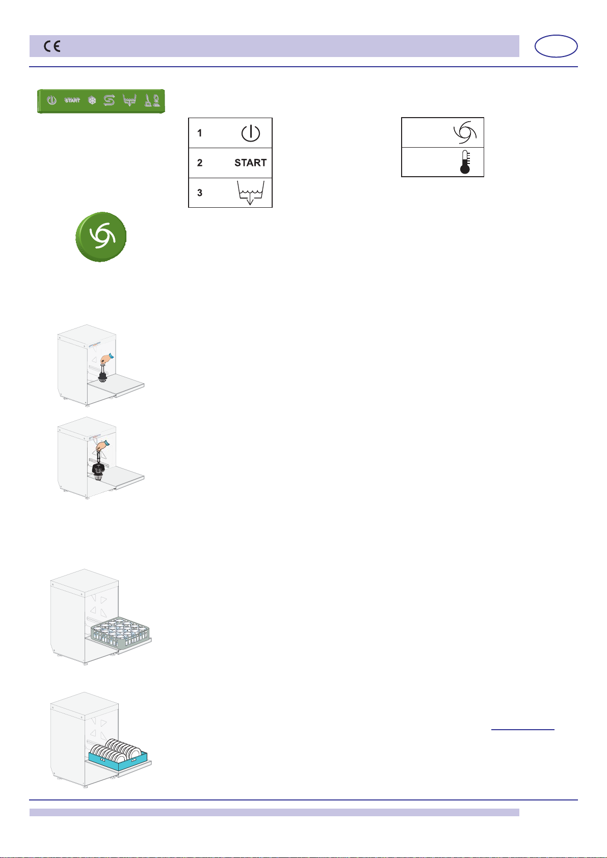
1.4 Temperature adjustment
If necessary, the water temperature of the wash and rinse cycles can be adjusted by means
of the fi ne-adjustment screws on the respective thermostats.
The recommended temperatures are 55°C for the wash cycle (tub) and 85 - 90°C for the
rinse cycle (boiler).
1.5 Rinse aid dispenser operation
Operation: It utilizes the difference in combined pressure caused by turning the washing
pump on and off, and the rinse pressure.
Water connection:
1) Connect the dispenser tube fi tting A to the pump, by means of the rubber tube installed
in the appliance (pump pressure).
2) Connect the small black rubber tube by the brass delivery fi tting B to the connection in
the boiler (injector).
3) Make sure that the green product suction tube is inserted on the special fi tting C and that
the small fi lter and the ballast are inserted in the rinse aid tub.
Priming: To prime the dispenser, turn on the appliance and carry out several complete
wash cycles.
Adjustment: With each rinse cycle, the dispenser draws an amount of rinse aid, adjustable
from 0 to 4 cc, equivalent to a length of 0 to 30 cm drawn into the suction tube.
In order to regulate the dispenser to the minimum amount, turn the adjustment screw D
completely clockwise. For the maximum amount, turn the screw anticlockwise about 20
complete turns.
For the correct amount of rinse aid, see the paragraph 5.3 Use of rinse aid.
Note: for each turn of the screw the amount of the product drawn into the tube varies by 1.6
cm, equivalent to 0.2 cc/turn (about 0.21g/turn with a concentration of 1.05 g/cm³ of rinse
aid). The rinse aid cannot function properly if the difference in level between the bottom of
the machine and the container exceeds 80 cm.
THE DISPENSERS ARE PRE-SET TO A 5 CM OF TUBE (0,65 gr.) INTAKE OF PRODUCT
FOLLOWING A TEST PHASE SYSTEM CHECK. THIS MEASUREMENT SHOULD BE
ADJUSTED ACCORDING TO THE TYPE OF RINSE AID USED AND WATER HARDNESS.
2. 2. DETERGENT DISPENSER RETROFIT
2.1 Electrical connection
Follow the wiring diagram attached to the machine.
2.2 Water connection
a) A Ø 12 hole must be made on the back of the appliance.
In some appliances the hole has already been made and is closed with a plastic cap.
Remove the cap from the hole and fi t the delivery connection.
b) Otherwise, drill one of the same diameter as the injector on the back part of the tub (see
image 3). This operation must be carried out by the Technical Service.
The hole must be made above the water level.
Important: make the hole in a position distant from the overfl ow tube, so that detergent
does not fl ow out immediately. Fix the dispenser in a vertical position with tube connectors
turned downwards, making sure not to place it on energized components.
Clean the inside of the machine from any drilling residual.
!
!
image 2
15185
Ø 10