manuals.online logo
Brands
  1. Home
  2. •
  3. Brands
  4. •
  5. Metra Electronics
  6. •
  7. Automobile Accessories
  8. •
  9. Metra Electronics 99-8205 User manual

Metra Electronics 99-8205 User manual

Other Metra Electronics Automobile Accessories manuals
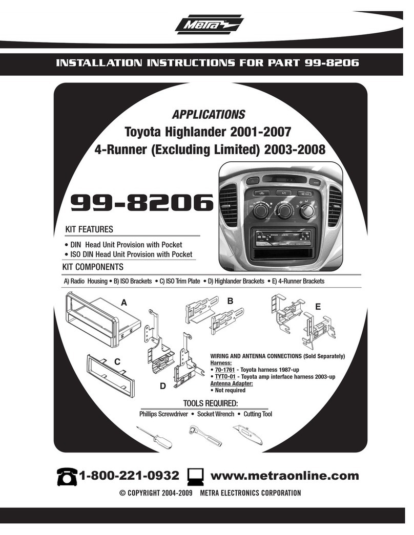
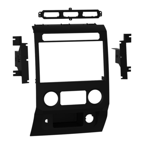
Metra Electronics 99-7424 User manual

Metra Electronics

Metra Electronics 99-7424 User manual

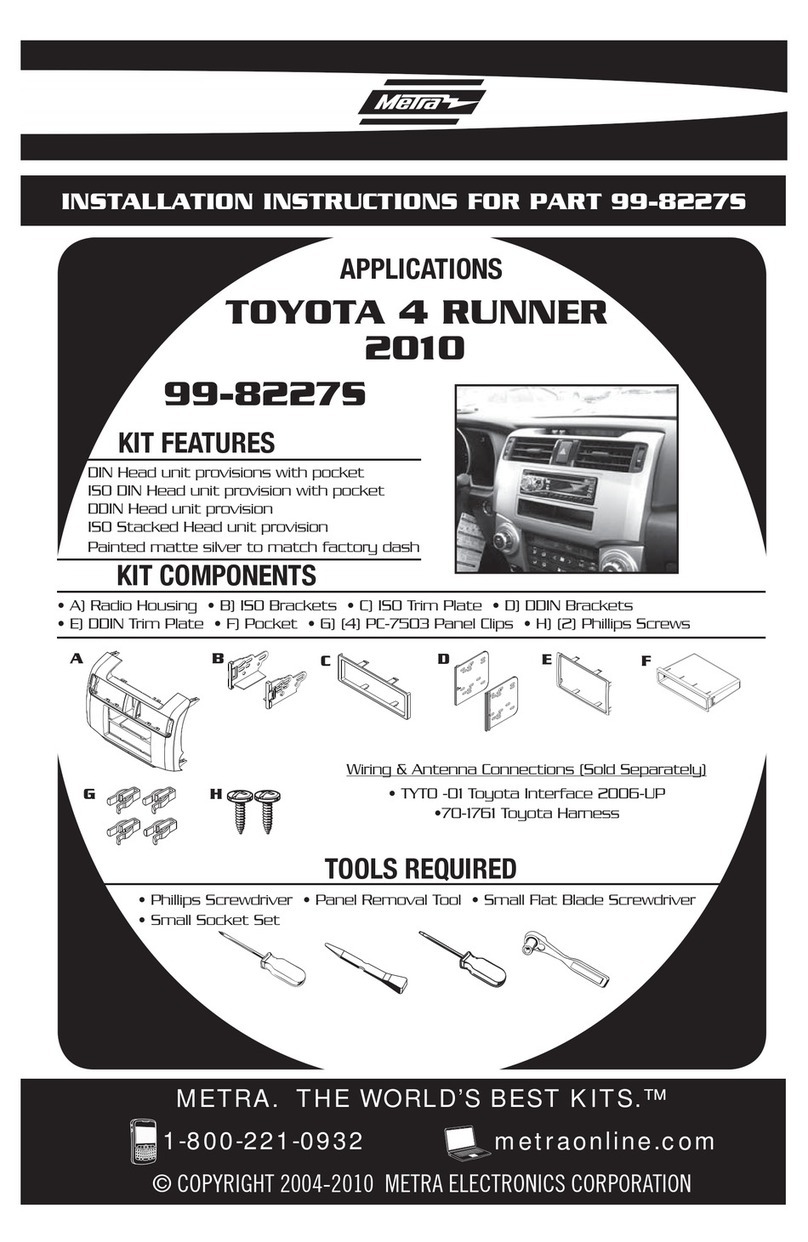
Metra Electronics 99-7581 User manual

Metra Electronics

Metra Electronics 99-7581 User manual

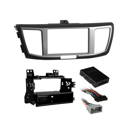
Metra Electronics 99-7352B User manual

Metra Electronics

Metra Electronics 99-7352B User manual

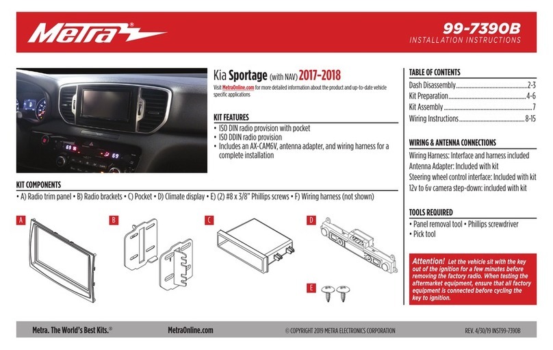
Metra Electronics 70-1722 User manual

Metra Electronics

Metra Electronics 70-1722 User manual

Metra Electronics 99-7803G User manual

Metra Electronics

Metra Electronics 99-7803G User manual

Metra Electronics 95-7332 User manual

Metra Electronics

Metra Electronics 95-7332 User manual

Metra Electronics 99-3009 User manual

Metra Electronics

Metra Electronics 99-3009 User manual

Metra Electronics 99-7581 User manual

Metra Electronics

Metra Electronics 99-7581 User manual

Metra Electronics 99-8245CHG User manual

Metra Electronics

Metra Electronics 99-8245CHG User manual

Metra Electronics 99-3042 User manual

Metra Electronics

Metra Electronics 99-3042 User manual

Metra Electronics 95-8224 User manual

Metra Electronics

Metra Electronics 95-8224 User manual

Metra Electronics 99-7337B User manual

Metra Electronics

Metra Electronics 99-7337B User manual

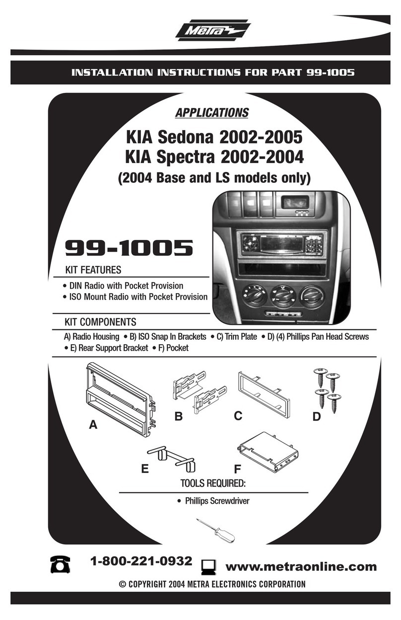
Metra Electronics 99-1005 User manual

Metra Electronics

Metra Electronics 99-1005 User manual

Metra Electronics 99-5816 User manual

Metra Electronics

Metra Electronics 99-5816 User manual

Metra Electronics 95-3105 User manual

Metra Electronics

Metra Electronics 95-3105 User manual

Metra Electronics 95-6532B User manual

Metra Electronics

Metra Electronics 95-6532B User manual

Metra Electronics 99-3307G User manual

Metra Electronics

Metra Electronics 99-3307G User manual

Metra Electronics 95-7417 User manual

Metra Electronics

Metra Electronics 95-7417 User manual

Metra Electronics 99-8218 User manual

Metra Electronics

Metra Electronics 99-8218 User manual

Metra Electronics 99-5828CH User manual

Metra Electronics

Metra Electronics 99-5828CH User manual

Metra Electronics 99-1003 User manual

Metra Electronics

Metra Electronics 99-1003 User manual

Metra Electronics DP-3002B User manual

Metra Electronics

Metra Electronics DP-3002B User manual

Metra Electronics 99-7392B User manual

Metra Electronics

Metra Electronics 99-7392B User manual

Metra Electronics 99-7316 User manual

Metra Electronics

Metra Electronics 99-7316 User manual

Popular Automobile Accessories manuals by other brands

Magneti Marelli AC161 Installation instruction

Magneti Marelli

Magneti Marelli AC161 Installation instruction

FDI uEZ GUI Start here

FDI

FDI uEZ GUI Start here

JCROffroad JT Install instructions

JCROffroad

JCROffroad JT Install instructions

Rostra VOXXElectronics 250-1930 owner's guide

Rostra

Rostra VOXXElectronics 250-1930 owner's guide

TOP VEHICLE TECH GR3FORD5 installation manual

TOP VEHICLE TECH

TOP VEHICLE TECH GR3FORD5 installation manual

Safe Fleet PRIME DESIGN AR-2000-BLK manual

Safe Fleet

Safe Fleet PRIME DESIGN AR-2000-BLK manual

Skoda Fabia Combi 5J Fitting instructions

Skoda

Skoda Fabia Combi 5J Fitting instructions

Camcar 40077 Al Mounting instructions

Camcar

Camcar 40077 Al Mounting instructions

Camcar 40089 AL Mounting instructions

Camcar

Camcar 40089 AL Mounting instructions

Impac Tradesman 2000 installation manual

Impac

Impac Tradesman 2000 installation manual

DVB OFFROAD BRSB-01 installation manual

DVB

DVB OFFROAD BRSB-01 installation manual

Safari Snorkel SS385HF installation guide

Safari Snorkel

Safari Snorkel SS385HF installation guide

ULTIMATE SPEED 279746 Assembly and Safety Advice

ULTIMATE SPEED

ULTIMATE SPEED 279746 Assembly and Safety Advice

SSV Works DF-F65 manual

SSV Works

SSV Works DF-F65 manual

ULTIMATE SPEED CARBON Assembly and Safety Advice

ULTIMATE SPEED

ULTIMATE SPEED CARBON Assembly and Safety Advice

Witter F174 Fitting instructions

Witter

Witter F174 Fitting instructions

WeatherTech No-Drill installation instructions

WeatherTech

WeatherTech No-Drill installation instructions

TAUBENREUTHER 1-336050 Installation instruction

TAUBENREUTHER

TAUBENREUTHER 1-336050 Installation instruction

manuals.online logo
manuals.online logoBrands
  • About & Mission
  • Contact us
  • Privacy Policy
  • Terms and Conditions

Copyright 2025 Manuals.Online. All Rights Reserved.

INSTALLATION INSTRUCTIONS FOR PART 99-8205
1-800-221-0932 www.metraonline.com
©COPYRIGHT 2004-08 METRA ELECTRONICS CORPORATION
KIT FEATURES
•DIN head unit provision
•ISO DIN head unit provision
•DDIN head unit provision
-Excluding 2005-2008 Matrix
•Stacked ISO DIN head unit provision
-Excluding 2005-2008 Matrix
A) DDIN Faceplate (excluding 2005-2008 matrix) • B) ISO DIN Faceplate (excluding 2005-2008 matrix)
•C) ISO DIN Faceplate 2005-2008 Matrix D) Pocket • E) Mounting Brackets • F) ISO Trim Plate • G) ISO Brackets
KIT COMPONENTS
TOOLS REQUIRED:
99-8205
A
APPLICATIONS
Toyota Matrix 2003-2008
Pontiac Vibe 2003-2008
Cutting Tool • Phillips Screwdriver • Socket Wrench
BCDE
FGHIJK
•H) ISO Spacers • I) Rear Support • J) (4) #6x1/4” Phillip Screws • K) (4) #8x3/8” Phillip Screws
TABLE OF CONTENTS
99-8205
Dash Disassembly . . . . . . . . . . . . . . . . . . . . . . . . . . . . . . . . . . .1,2
Kit Assembly . . . . . . . . . . . . . . . . . . . . . . . . . . . . . . 3, 4, 5, 6, 7,8
Final Assembly . . . . . . . . . . . . . . . . . . . . . . . . . . . . . . . . . . . . . . . 9
K
NOWLEDGE IS
P
OWER
Enhanceyour installation and fabrication skillsby
enrolling in the most recognizedandrespected
mobile electronics school in our industry.
Log onto www.installerinstitute.comor call
800-354-6782 for more informationandtake steps
toward abetter tomorrow.
99-8205
1
Disconnect the negative battery
terminal to prevent an accidental
short circuit.
1
Unclip the bottom edge of the radio
trim panel then lift up and out to
remove.
(Figure A)
2
TOYOTAMATRIX 2003-2008
PONTIAC VIBE 2003-2008
Remove (4) 10 MM bolts securing
the factory radio.
(Figure B)
3
DASH DISASSEMBLY
A
SCAN
SEEK
TRACK
TUNE
AM FM1 FM2 DISK
B
99-8205
KIT ASSEMBLY
2
Attach the pocket to the back of the
ISO/DIN Faceplate (by holding the
faceplate upside down and inserting
the right edge of the pocket into
place then pushing the rest of the
pocket onto the lip) and mount with
(2) #8X3/8” Phillips screws.
(Figure A)
2
3
A
Secure the mounting brackets to the
pocket with (4) #6X1/4” Phillips
screws. (
Figure C)
Choose the correct faceplate for your
application. The 2005-2008 Matrix
faceplate is smaller than the other
supplied faceplate.
1
#8x3/8” Screw
#8x3/8” Screw
B
C
#6x1/4” Screws
#6x1/4” Screws Two
#8x3/8” Screws
DIN HEAD UNIT PROVISION
NOTE: For the 2005-2008 Matrix,
break away the shaded clips along
the scored lines. (
Figure B)
99-8205
KIT ASSEMBLY
3
Slide the DIN cage into the Radio
Housing and secure by bending the
metal locking tabs down. (
Figure E)
5
Slide the aftermarket head unit into
the cage and secure. (
Figure F)
6
E
F
DIN HEAD UNIT PROVISION
D
#6x1/4” Screws
#6x1/4” Screws Two
#8x3/8” Screws
Mount the rear support to the back
of the pocket with (2) #8X3/8”
Phillips screws. (
Figure D)
4
4
ISO DIN HEAD UNIT PROVISION
99-8205
KIT ASSEMBLY
Attach the
the pocket to the back of the
ISO/DIN Faceplate (by holding the face-
plate upside down and inserting the right
edge of the pocket into place then push-
ing the rest of the pocket onto the lip)
and mount with (2) #8X3/8” Phillips
screws. (Figure A)
2
A
Secure the mounting brackets to the
pocket with (4) #6X1/4” Phillips
screws. (
Figure C)
3
#8x3/8” Screw
#8x3/8” Screw
B
#6x1/4” Screws
#6x1/4” Screws Two
#8x3/8” Screws
C
NOTE: For the 2005-2008 Matrix,
break away the shaded clips along
the scored lines. (
Figure B)
Choose the correct faceplate for your
application. The 2005-2008 Matrix
faceplate is smaller than the other
supplied faceplate.
1
5
ISO DIN HEAD UNIT PROVISION
99-8205
KIT ASSEMBLY
Mount the ISO Brackets to the head
unit with the screws supplied with
the unit. (
Figure E)
5
Mount the rear support to the back
of the pocket with (2) #8x3/8”
Phillips screws. (
Figure D)
4
Slide the the head unit into the radio
opening until the side clips engage.
(
FigureF)
6
Snap the Trim plate into the Radio
Housing. (
Figure F)
7
#6x1/4” Screws
#6x1/4” Screws Two
#8x3/8” Screws
E
D
F
6
DOUBLE DIN HEAD UNIT PROVISION
99-8205
KIT ASSEMBLY
Cut and remove the bottom portion
(Displayed) of the mounting brack-
ets. (
Figure A)
1
NOTE: 2005-2008 Matrix not
applicable.
A
Cut and remove the center bar from
the DDIN faceplate. (
Figure B)
2
Attachthe ISO spacers to the
mounting brackets by inserting the
(4) bosses on each spacer into the
(4) holes in each bracket. (
Figure C)
3
Attachthe mounting brackets to the
DDIN head unit with the screws sup-
plied with the unit. (
Figure D)
4
Attach the DDIN faceplate over the
head unit bysnapping the bracket
clips into the faceplate slots.
(
Figure E)
5
B
C
D
E
STACKED ISO DIN HEAD UNIT PROVISION
Cut and remove the bottom portion
(Displayed) of the mounting brack-
ets. (
Figure A)
1
A
Attach the ISO spacers to the mount-
ing brackets by inserting the (4)
bosses on each spacer into the (4)
holes in each bracket. (
Figure B)
2
Attach the mounting brackets to the
DDIN head unit with the screws sup-
plied with the unit. (
Figure C)
3
Attach the DDIN faceplate over the
head unit bysnapping the bracket
clips into the faceplate slots.
(
Figure D)
4
B
C
D
99-8205
KIT ASSEMBLY
7
NOTE: 2005-2008 Matrix not
applicable.
8
FINAL ASSEMBLY
1
Locate the factory wiring harness in the dash and make the connection as shown.
Metra recomends using the proper mating adapter and making the connections as
shown. (Isolate and individually tape off the ends of any unused wires to prevent
electrical short circuit.)
2
Re-connect the negative battery terminal and test the unit for proper operation.
3
Reassemble radio and dash assemblies in reverse order of disassembly.
A
A) Strip wire ends back 1/2"
B) Twist ends together
C) Solder
D) Tape
B
C
D
Make wiring connections using the EIA color code chart shown below and the instructions included with the head
unit. Metra recommends making connections as shown below; Strip, Splice, Solder, Tape. Isolate and individually
tape off ends of anyunused wires to prevent electrical short circuit.
12V Ignition / Acc . . . Red
12V Batt / Memory . . Yellow
Ground . . . . . . . . . . . Black*
Power Antenna . . . . . Blue
Amp Turn-On . . . . . . Blue / White
Amp Ground . . . . . . . Black / White
Illumination. . . . . . . . Orange
Dimmer . . . . . . . . . . Orange / White
Right Front (+) . . . . . Gray
Right Front (-). . . . . . Gray / Black
Left Front (+) . . . . . . White
Left Front (-) . . . . . . . White / Black
Right Rear (+). . . . . . Violet
Right Rear (-) . . . . . . Violet / Black
Left Rear (+). . . . . . . Green
Left Rear (-) . . . . . . . Green / Black
*NOTE: When Black a wire is not present, ground radio to vehicle chassis.
All colors may not be present on all leads due to manufacturer’s specifications.
METRA / EIA WIRING CODE
FINAL WIRING CONNECTIONS
99-8205
KIT ASSEMBLY