■■■■■■■■■■■■■■■■■■■■■■ Table of figures
807 Dosing Unit ■■■■■■■■ V
Table of figures
Figure 1 807 Dosing Unit ................................................................................ 5
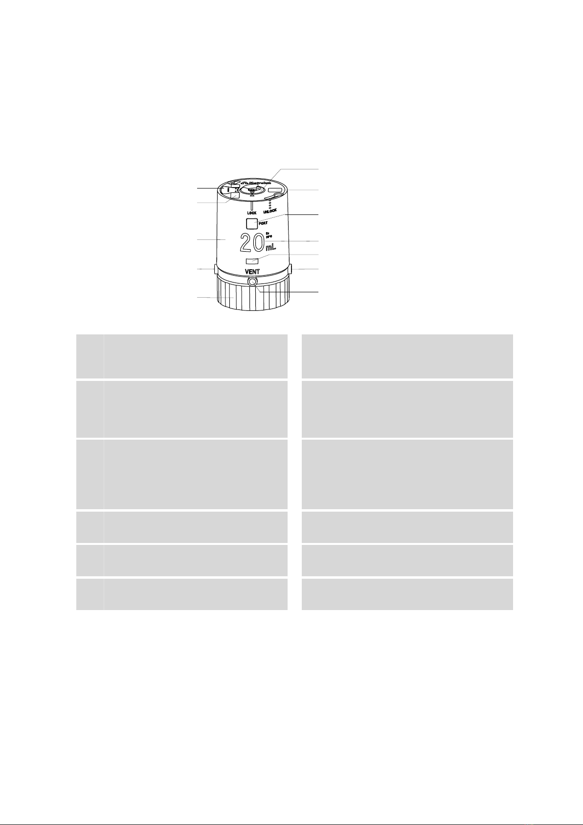
Figure 2 807 Dosing Unit - Components ......................................................... 6
Figure 3 Cylinder unit ...................................................................................... 8
Figure 4 807 Dosing Unit - Ports ..................................................................... 9
Figure 5 Removing the housing ..................................................................... 10
Figure 6 Greasing the centering tube and interior edges of the housing ........ 11
Figure 7 Mounting the storage vessel and the holder .................................... 12
Figure 8 Marking rib on housing and distributor ............................................ 13
Figure 9 Locking the housing ........................................................................ 13
Figure 10 Mounting the adsorber tube ........................................................... 14
Figure 11 Mounting filling tubes ..................................................................... 15
Figure 12 Dosing unit on the reagent bottle .................................................... 16
Figure 13 Mounting the tubing and the buret tip ............................................ 17
Figure 14 Air bubbles in the cylinder ............................................................... 20
Figure 15 Removing the housing ..................................................................... 22
Figure 16 Cylinder unit on the distributor ........................................................ 23
Figure 17 Dosing cylinder damaged ................................................................ 23
Figure 18 Dosing cylinder with dosing piston .................................................. 25
Figure 19 Inserting the dosing piston .............................................................. 26
Figure 20 Centering tube on the dosing cylinder ............................................. 27
Figure 21 Stopper of the dosing piston flush with the upper edge of the hous-
ing .................................................................................................. 27
Figure 22 Marking ribs on the centering tube and edge of the distributor ....... 28
Figure 23 Marking rib on housing and distributor ............................................ 29
Figure 24 Locking the housing ........................................................................ 29
Figure 25 Piston stopper flush with the upper edge of the housing ................. 30
Figure 26 Triangles on the upper side of the dosing unit when the stopcock is set
correctly .......................................................................................... 30
Figure 27 Dosing unit completely mounted ..................................................... 30
Figure 28 Valve disc in the cylinder base .......................................................... 32
Figure 29 Distributor disc with 4 ports (in the distributor) ................................ 32
Figure 30 Data chip and contact pin ............................................................... 41