SEA Cougar 270 User manual

Sistemi Elettronici
di Apertura Porte e Cancelli
®
SEA S.p.A.
Zona industriale 64020 S.ATTO Teramo - (ITALY)
Tel. +39 (0)861 588341 r.a. Fax +39 (0)861 588344
www.seateam.com
Italiano
English
Français
Español
Rev.00 - 06/201667411965
POSITION GATE
Cougar 270/390

Fig. 1
D
B
A
E
C
Fig. 2
2
Sistemi Elettronici
di Apertura Porte e Cancelli
®
Cougar
270-390
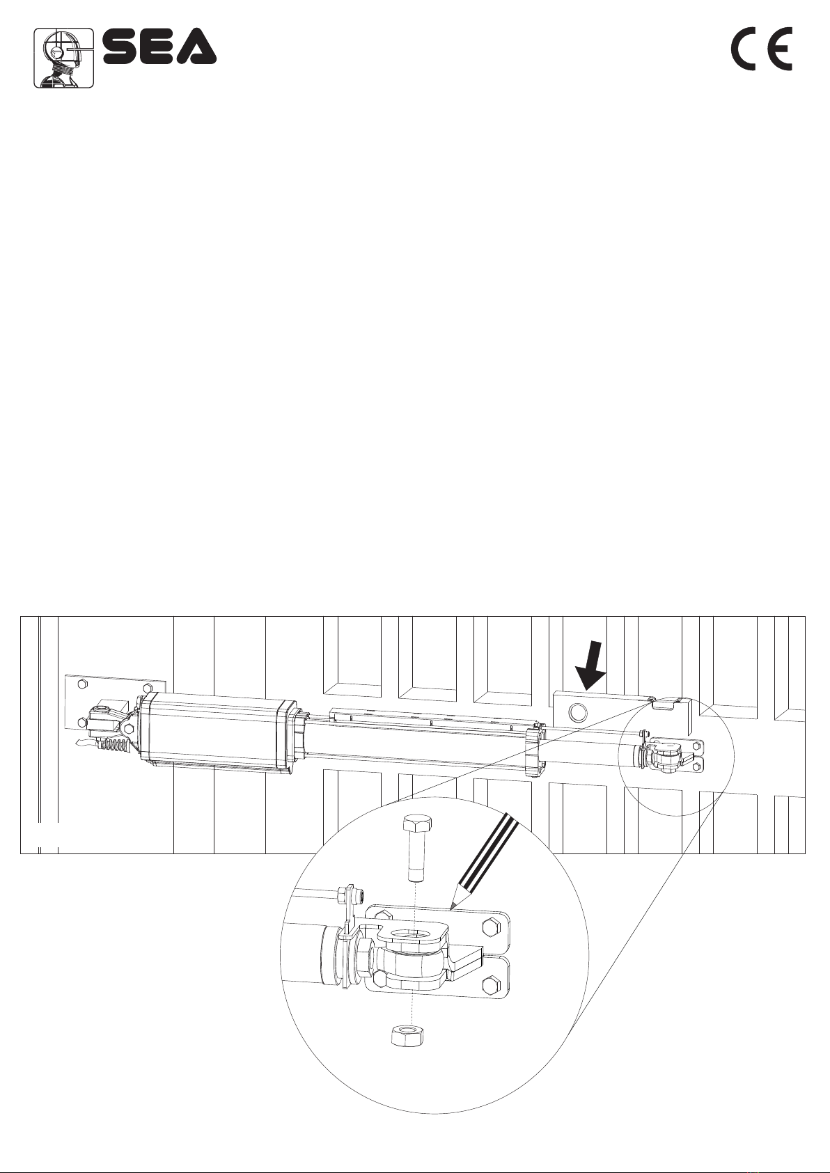
POSIZIONAMENTO DELL’ATTACCO ANTERIORE
Una volta fissato l’operatore sull’attacco posteriore portare l’anta del cancello in posizione di chiusura ed eseguire le seguenti operazioni:
1)Tirare fuori completamente lo Stelo cromato, poi riportarlo indietro di minimo 1 cm
2) Fissare lo stelo sul attacco anteriore (Fig. 4).
3) Posizionare l’operatore in modo che risulti perfettamente orizzontale e quindi segnare la posizione dell’attacco anteriore (Fig.3).
Attenzione: evitare di saldare l’attacco anteriore con lo stelo dell’operatore già fissato; i residui (schizzi) di saldatura potrebbero
compromettere la cromatura dello stelo.
POSITIONING OF THE FRONT FIXATION
Once the operator has been mounted on the back fixation close the leaf and do as follows:
1) Pull out completely the chromium plated rod, afterwards bring it back about 1 cm
2) Fix the rod on the front fixation (Fig. 4).
3) Position the operator perfectly horizontal and mark the position of the front fixation (Fig.3).
Attention: Avoid the welding of the front fixation to the rod of the operator already fixed as the welding residual (squirt) could ruin the chromium -
plating of the rod.
POSITIONNEMENT ATTAQUE ANTERIEUR
Après avoir fixé l’opérateur sur l’attaque postérieur fermer le vantail et exécuter le suivantes opérations:
1)Sortir complètement la tige chromée, après la rentrer d’au moins 1 cm.
2) Fixer la tige sur l’attaque antérieur (Fig. 4).
3) Positionner l’opérateur de façon parfaitement horizontal donc marquer la position de l’attaque antérieur (Fig. 3).
Attention: éviter de souder l’attaque antérieur avec la tige de l’opérateur déjà fixée: Les déchets de soudure pourraient compromettre le
chromage de la tige.
POSICIONAMIENTO DEL ENGANCHE ANTERIOR
Una vez fijado el operador en el enganche posterior llevar el anta de la cancela en posicion de cierre y efectuar las siguientes operaciones:
1) Jalar hacia fuera completamente la varilla cromada,de minimo 1 cm.
2) Fijar la varilla en el enganche anterior (Fig. 4).
3) Posicionar el operador en modo que resulte prefectamnete horizontal y por tanto señalar la posicion del enganche anterior (Fig. 3).
Atencion: evitar de soldar el enganche anterior con la varilla del operador ya fijado; los residuos (salpicaduras) de soldadura podria
comprometer la cromadura de la carrera.
3
Fig. 3
Fig. 4
Sistemi Elettronici
di Apertura Porte e Cancelli
®

ATTENZIONE: Durante la fase di montaggio dei dadi del tirante, fare attenzione a non far ruotare il tirante del Position Gate perché
potrebbe arrecare malfunzionamenti al Position Gate stesso.
WARNING: During the assembly of the tie rod nuts, be careful not to rotate the rod of the Position Gate because it could cause
malfunctions to the Position Gate itself.
AVERTISSEMENT: Lors de l'assemblage des écrous de tirants, veillez à ne pas faire tourner la tige de le Position Gate, car elle pourrait
provoquer des dysfonctionnements à le Position Gate lui-même.
ADVERTENCIA: Durante el montaje de las tuercas del tirante, atención que el tirante del Position Gate no ruede, ya que podría causar
fallos de funcionamiento en el Position Gate.
MONTAGGIO SNODO SFERICO e PIASTRINA
Montare lo snodo sferico come mostrato in Fig.5.
Montare la piastrina come mostrato in Fig.6.
BALL JOINT and PLATELET MOUNTING
Mount the ball joint as shown in Fig.5.
Mount the platelet as shown in Fig.6.
MONTAGGIO POSITION GATE - POSITION GATE INSTALLATION
INSTALLATION POSITION GATE - MONTAJE POSITION GATE
MONTAGE JONCTION SPHERIQUE ET PLAQUE
Monter le jonction sphérique comme montré en Fig.5.
Monter la plaque comme montré en Fig.6.
MONTAJE ARTICULACION ESFERICA Y PLAQUITA
Montar la articulación esférica como Fig.5.
Montar la plaquita como Fig.6.
4
Fig. 5 Fig. 6
Fig. 7
Sistemi Elettronici
di Apertura Porte e Cancelli
®

REGOLAZIONE SNODO SFERICO
Regolare lo snodo sferico come mostrato in Fig.8 e Fig.9.
BALL JOINT ADJUSTMENT
Adjust the ball joint as shown in Fig.8 and Fig.9.
MONTAGGIO SINISTRO
LEFT ASSEMBLY
MONTAGE GAUCHE
MONTAJE IZQUIERDO
MONTAGGIO DESTRO
RIGHT ASSEMBLY
MONTAGE DROITE
MONTAJE DERECHO
5
AJUSTEMENT DE LA JONCTION SPHERIQUE
Ajuster la jonction sphérique comme illustré à la figure 8 et la figure 9.
REGULACION ARTICULACION ESFERICA
Regular la articulación esférica como Fig.8 y Fig.9.
5 mm
Max
5 mm
Max
Fig. 8
Fig. 9
Sistemi Elettronici
di Apertura Porte e Cancelli
®

INSTALLAZIONE DEL CARTER DI PROTEZIONE
Verificare di aver inserito la cornice in plastica antivibrazione (B) prima d’inserire l’estruso copristelo (Fig. 11).
PORTECTION COVER MOUNTING
Make sure to have inserted the antivibration plastic frame (B) before inserting the rod cover extrusion (Fig. 11).
INSTALLATION DU CARTER DE PROTECTION
S’assurer d’avoir inséré le quadre en plastique anti-vibration (B) avant d’insérer le couvre tige extrusé (Fig. 11).
INSTALACION DEL COFRE DE PROTECCION
Verificar de haber insertado el marco en plastica antivibracion (B) antes de insertar el estruso cubrevarilla (Fig. 11).
N.B.: Nell’inserimento del carter copristelo fare attenzione a non danneggiare i cavi del Position Gate.
N.B.: When inserting the piston cover, pay attention to not damage the cables of the Position Gate.
Remarque: Dans l'insertion du carter couvre -tige faire attention à ne pas endommager les câbles du Position Gate.
Nota: en fase de introducion del cofre cobreperno poner atención para que non se dañen los cables del Position Gate.
6
FISSAGGIO CONNETTORE
Per evitare che nel montaggio del copristelo vengano tranciati i cavi, fissare il connettore (A) al tirante con una fascetta, come mostrato in
Fig.10.
CONNECTOR FIXING
To prevent that during installation of the rod cover the cables are cut, fix the connector (A) to the rod with a clamp, as shown in Figure 10.
FIXATION CONNECTEUR
Pour éviter que lors de l'installation du couvercle de tige les câbles sont coupés, fixer le connecteur (A) à la tige avec une bande, comme
indiqué sur la figure 10.
FIJADO CONECTOR
Para evitar que en el montaje del copristelo sean cortados los cables, fijar el conector (A) al tirante con una faja, como enseñado en Fig.10.
Fig. 10
(A)
Fig. 11
B
Sistemi Elettronici
di Apertura Porte e Cancelli
®

DATI1 - DATA1 - DONNÉES1 - DATOS1
Bianco-White-Blanc-Blanco
P11/P01
Verde-Green-Vert-Verde
P01/P11
Marrone-Brown-Marron-Marrón
Fig. 13
PASSAGGIO CAVI POSITION GATE
POSITION GATE CABLES’ PASSAGE
PASSAGE CÂBLES POSITION GATE
PASAJE CABLES POSITION GATE
Fig. 12
7
Sistemi Elettronici
di Apertura Porte e Cancelli
®

Sistemi Elettronici
di Apertura Porte e Cancelli
International registered trademark n. 804888
®
SEA S.p.A.
Zona industriale 64020 S.ATTO Teramo - (ITALY)
Tel. +39 0861 588341 r.a. Fax +39 0861 588344
www.seateam.com
This manual suits for next models
1
Other SEA Gate Opener manuals

SEA
SEA SUPER FULL TANK 20 G6 380V User manual

SEA
SEA COMPACT Series Original instructions

SEA
SEA GER Instruction manual

SEA
SEA ORION BOX 24V User manual

SEA
SEA LEPUS BOX 120V/24V User manual

SEA
SEA FLIPPER 110V User manual

SEA
SEA Libra Mini Tank User manual

SEA
SEA TORG Instruction manual

SEA
SEA LIBRA Series Original instructions

SEA
SEA SCUTI User manual

SEA
SEA ERG User guide

SEA
SEA ALPHA 330 STANDARD Original instructions

SEA
SEA UNIGATE 1I User manual

SEA
SEA Field Original instructions

SEA
SEA 1110 User manual

SEA
SEA SURF Series User manual

SEA
SEA GATE 2 DG INVERTER User manual

SEA
SEA TAURUS BOX 1000 User manual

SEA
SEA SURF K 500 User manual

SEA
SEA JACK Original instructions


