MICRO-AIR CLEAN AIR BOOTH User manual

This manual contains specific cautionary statements relative to worker safety. Read this manual thoroughly and follow
as directed. It is impossible to list all of the hazards of dust control equipment. It is important that use of the equipment
be discussed with a Micro-Air Representative. Persons involved with the equipment or systems should be instructed how
to operate in a safe manner.
CLEAN AIR BOOTH (CAB)
Installation and Operation Manual
MICRO AIR
www.microaironline.com
2
CAB MICRO AIR
WARNINGS:
Installation can cause exposure to live components. Disconnect electrical power before
proceeding with installation. Proper Lock Out / Tag Out procedures should be used. All electrical
work must be done by a qualified electrician according to Local, State and National codes.
Avoid mixing combustible materials, such as buffing lint, paper, wood, aluminum, and
magnesium dust with dust generated from grinding ferrous metals due to the potential fire
hazard caused by sparks in the dust collector
Under no conditions should the persons operating the dust collector be allowed to put cigarettes
or any burning object into the inlet grille, hood, or ducting of any dust collector system.
All users of Micro-Air Equipment should comply with all National and Local Fire Codes and/or
other appropriate codes when determining the location and operation of dust control equipment.
Improper installation or operation of this equipment can cause damage to equipment and / or
injury to personnel. The installation / operation manual must be read and followed in its entirety.
CAB SPECIFICATIONS:
Input Voltage:
230/460V, 60 Hz, 3-Phase
575V, 60 Hz, 3-Phase
Motor Options:
3HP, 3-Phase, TEFC Motor, 3450 RPM
3HP, 3-Phase, TEFC Motor, 3450 RPM, Explosion Rated
5HP, 3-Phase, TEFC Motor, 3450 RPM
5HP, 3-Phase, TEFC Motor, 3450 RPM, Explosion Rated
Maximum Current:
3HP:
230V - 7.4 Amps
460V - 3.7 Amps
575V - 3.2 Amps
5HP:
230V - 14.0 Amps
460V - 7.0 Amps
575V - 5.5 Amps
Cabinet Dimensions
Single:
101" H x 48" W x 36" D, 850 lbs.
and Weights:
Double:
101" H x 96" W x 36" D, 1700 lbs.
Triple:
101" H x 144" W x 36" D, 2550 lbs.
Quad.:
101" H x 192" W x 36" D, 3400 lbs.
Filter Area (80/20 Filter
Single:
1250 Sq. Ft.
Media):
Double:
2500 Sq. Ft.
Triple:
3750 Sq. Ft.
Quad.:
5000 Sq. Ft.
Dust Tray Capacity:
4.75 Cu. Ft.
EQUIPMENT / TOOLS REQUIRED:
Equipment and tools needed for proper installation will include the following:
Crane or Lift Truck
Screw Driver
Lift Straps or Chain
Sockets
Pipe Wrench
3
CAB MICRO AIR
PRE-OPERATING INSTRUCTIONS:
The Micro Air Clean Air Booth is shipped on multiple skids.
1. Inspect every skid for any visible damage that may have occurred during shipment. Report any damage
to the delivery carrier.
2. Remove the shipping crate, shipping straps and plastic wrap from unit. Discard skid and hardware.
3. Additional equipment that may be shipped separately includes:
HEPA After-Filter Kit
Silencer Assembly
Photohelic Kit
Booth Panels & Supports
Magnehelic Kit
Electrical Box
Air Regain Module
Exhaust Panels
ASSEMBLY OF UNIT:
1. Determine the location where the unit is to be installed. Be sure to allow sufficient room to access the
unit for servicing and maintenance on all sides.
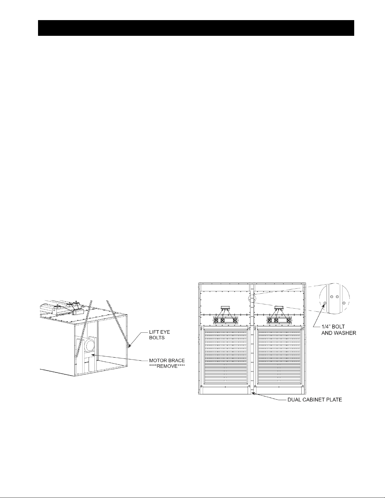
2. Connect chain/lift straps to provided eye-bolts located on top of unit (See FIG.1).
3. Securely attach chain/lift straps to crane. NOTE: Each lifting strap or chain should be rated for a
minimum of 2500 lbs.
4. Slowly lift unit into a standing position. CAUTION: If unit is lifted too quickly or too high it may lose
contact with the ground and swing side to side.
5. Once unit is in standing position readjust chain/lift straps and move unit into its final position.
6. Remove wooden brace used to secure motor (See FIG. 1).
7. If multiple units are to be assembled for a single booth, set each unit side by side.
8. Connect units using Dual Cabinet Plate and provided hardware (See FIG. 2). NOTE: To prevent
vibration noises in multi-cabinet units, silicon can be applied between units.
9. Using holes provided in bottom of cabinet, place four 1/2” anchor bolts for each cabinet.
FIG. 1 FIG. 2
4
CAB MICRO AIR
COMPRESSED AIR REQUIREMENTS / INSTALLATION:
NOTE: Clean, dry, compressed air at the specified air pressure is required for the cleaning system to
operate correctly. It is recommended that a pressure regulator and coalescing filter be installed between
the compressed air source and the inlet to the dust collector.
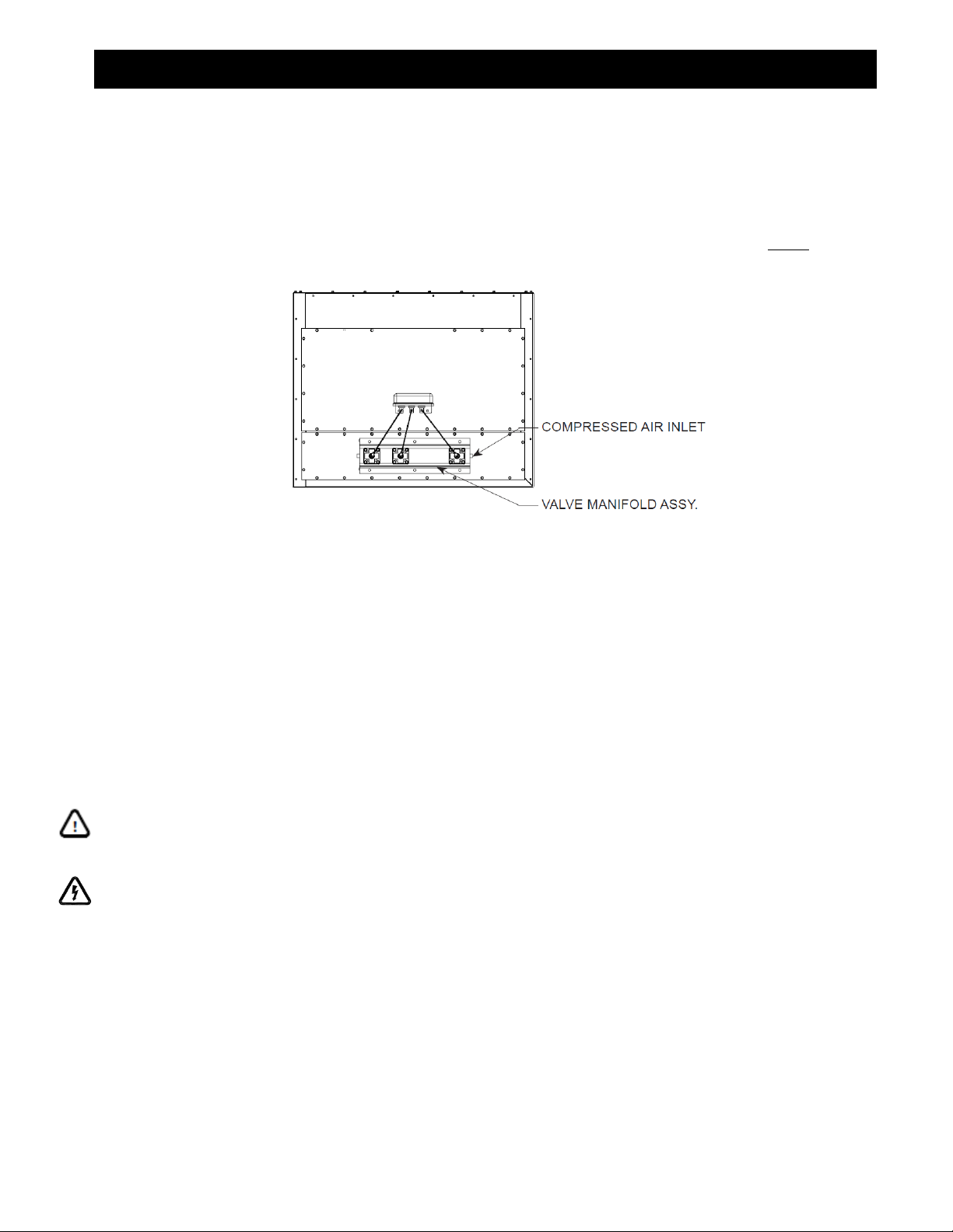
The compressed air inlet for the Roto-Pulse Cleaning System is at the top of the piping assembly located
on the front side of the unit (See FIG. 3). A minimum of a ¾” line and plant air at a pressure of 80 psi is
required, per unit, for proper operation of the Roto-Pulse Cleaning System.
FIG. 3
1. Remove plug from one end of Valve Manifold Assembly.
2. Connect ¾” air line to one end of each Valve Manifold Assembly. NOTE: Up to 2 Valve Manifold
Assemblies may be connected in series to the main trunk line. However additional Valve Manifold
Assemblies must be connected directly to the main air line.
3. The main air line must be sized appropriately for the number of units. The following shows minimum
recommended sizes:
Single Unit:
¾” Main Compressed Air Line (Minimum)
Double Unit:
1” Main Compressed Air Line (Minimum)
Triple Unit:
1-¼” Main Compressed Air Line (Minimum)
Quad. Unit:
1-½” Main Compressed Air Line (Minimum)
ELECTRICAL INSTALLATION:
IMPORTANT: The following installation instructions should be performed by a qualified
electrician. The following installation steps are for general use. Refer to Local and National
electrical codes for installations in your area.
WARNING: Installation can result in exposure to high voltage. Disconnect power source before
performing this installation. Proper lock out / tag out procedures should be used.
1. Unpack electrical box from skid. Inspect for any shipping damages.
2. The CAB unit can be operated with a factory assembled electrical control box, which contains a timer
circuit for automatic filter cleaning, a motor starter circuit for START/STOP operation and overload
protection for motor/blower(s) provided.
3. The electrical box is completely wired from the factory. Prior to making any electrical connections,
VERIFY PROPER INPUT VOLTAGE has been used for wiring the electrical circuit. IMPROPER
VOLTAGE MAY RESULT IN PERMANENT DAMAGE TO ELECTRICAL COMPONENTS.
4. Before making electrical connections, mount the electrical control box to a rigid permanent structure,
such as the unit, booth, or nearby wall.
5
CAB MICRO AIR
5. Electrical connections for motor/blower(s), Roto-Pulse solenoid valves, and incoming power shall be
required upon installation. The electrical box includes a safety interlock switch that disconnects power
to the circuit when the enclosure is opened. To gain access inside the electrical box, simply rotate the
disconnect switch towards the OFF position until a distinct click occurs. Using a Phillips screwdriver,
release the external hardware clamps located around the perimeter of the NEMA enclosure to allow
access to the electrical box.
IMPORTANT: Solid state circuits are sensitive to electrostatic shock. Take measures to ensure
that minimal static charge is discharged before making adjustments or changes to wire
connections on the timer board.
6. Route wire conduit from electrical box enclosure to solenoid valves housed inside NEMA enclosure(s)
located above the air inlet and Roto-Pulse valves of each clean air unit. Conduit should be sized to
allow the appropriate number of wires (16 AWG stranded) for all solenoids used. NOTE: A single wire
can be used for the COM output of the timer board to reduce overall number of wires.
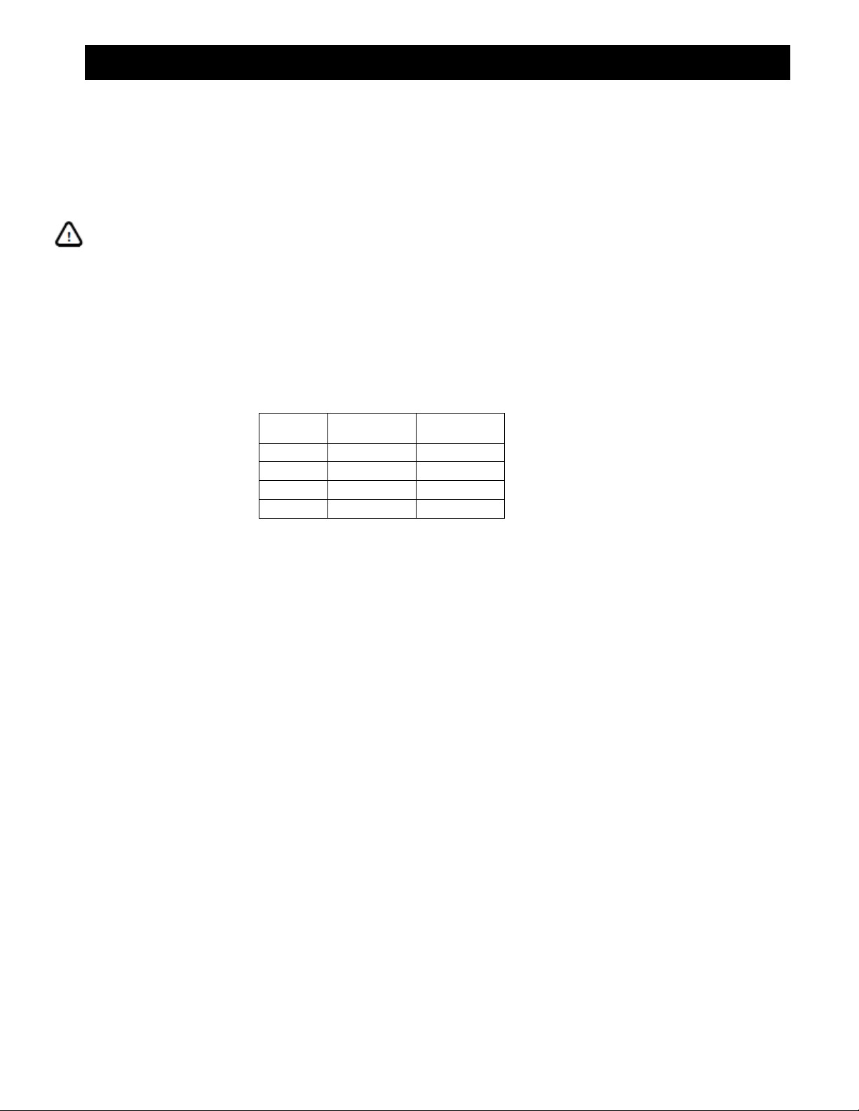
7. Run wire conduit(s) from electrical box enclosure to each motor/blower. Wire size will vary based upon
input voltage and horsepower. A table is shown below for recommended wire size. Consult local
electrical codes.
HORSE
POWER
VOLTAGE
WIRE SIZE
(AWG)
3
208 - 230V
14
3
460 - 575V
14
5
208 - 230V
12
5
460 - 575V
14
8. In most instances, three phase motors supplied for the CAB are dual voltage motors. When making
electrical connections to the motor(s) make certain to check motor wiring for correct input voltage.
(Refer to motor wiring label located upon each motor casing.)
9. After completing installation of electrical conduit, run wire and make appropriate electrical connections
as noted on wiring diagram (see PAGES 14-21).
10. After wires have been routed and connected, run conduit and wire connections for input power.
Connect wires to the input side of the interlock disconnect switch located inside the electrical box
enclosure. Use grounding termination located near by the disconnect switch for supply ground.
NOTE: Wire size for supply connections shall be sized according to the maximum horsepower rating of
all motors connected to the electrical box. Total motor load shall not exceed 20HP max.
11. The electrical box enclosure is grounded to the grounding terminal connected to supply ground. When
making electrical connections to each unit motor/blower it is recommended to ground the units. This
can be accomplished by running a ground wire (of equivalent wire gauge) from the motor ground to the
electrical box enclosure.
12. Upon completion of all wiring connections, close the electrical box enclosure, securing each of the
clamps around the enclosure and then turning the disconnect switch to the ON position. The unit is now
electrically ready for operation. Connect power via circuit breaker and/or three-phase disconnect switch.
The unit can now be energized by pushing the START button. Be certain that all other installation steps
have occurred before starting unit.
13. Upon pushing the START button located on the hinged door of the electrical box enclosure, the CAB
unit blower should begin to run and auto cleaning cycle should begin (unless Photohelic switch is used,
See Photohelic Switch). To stop the unit from running, push the STOP button also located on the
electrical box cover. Note that after-pulse cleaning (off-line cleaning) cycle will begin and auto-cleaning
will continue for approximately 1 to 2 minutes.
NOTE: If the enable switch located on the timer board is in the disable position, off-line cleaning will not
occur. If off-line cleaning is desired, simply move the switch to the enable position.

6
CAB MICRO AIR
PHOTOHELIC SWITCH:
For applications that require a Photohelic switch to monitor filter loading and control the operation of
auto-cleaning, additional wiring must be performed.
1. An optional Photohelic switch is made available for the CAB unit. Additional electrical installation is
required for this option in order to allow the switch to control the automatic cleaning system while
monitoring the pressure drop across the cartridge filters. Before wiring may begin, first locate the
Photohelic switch kit and mount it to a suitable location. Run air lines from the Photohelic switch ports to
the CAB unit. (Refer to Photohelic switch installation instructions, Page 13).
2. Once the Photohelic switch has been physically installed, route electrical conduit from the electrical box
enclosure to the Photohelic switch.
3. Next, route 2 wires (16 AWG min.) from the Photohelic switch to the electrical box enclosure. Allow
adequate length of wire to reach the upper left corner of the timer circuit board terminal strip labeled
PRESSURE SWITCH (See PAGES 14-22 for Wiring Diagrams).
IMPORTANT: Solid state circuits are sensitive to electrostatic shock. Take measures to ensure
that minimal static charge is discharged before making adjustments or changes to wire
connections on the timer board.
4. Prior to making connections to the PRESSURE SWITCH terminal, disconnect the two wires connected
to the terminal and also disconnect the other ends of the red wires that are connected to an auxiliary
contact (switch) located on a motor starter relay. Discard wires for this installation.
5. Connect each wire from the Photohelic switch to each terminal on the timer board indicated as
PRESSURE SWITCH. Be certain that only one wire is connected to each terminal.
6. Move the enable/disable switch on the timer board to the DISABLE position. This will inactivate the off-
line cleaning feature of the timer circuit, which is more common when only demanding automatic
cleaning when filters reach a certain static pressure level.
7. After all wiring connections have been completed; close the electrical box enclosure, securing the
enclosure cover with screw clamps provided. By hand, turn the safety switch disconnect to the ON
position.
8. Photohelic settings are to be adjusted for optimized cleaning performance. Typically, a low setting at 2”
w.c. and a high setting at 3” or 4” is a recommended starting point. Once the pressure drop across the
cartridge filters reaches the upper limit of the gauge, the automatic cleaning system will engage and
continue to run until the static pressure drops below the lower setting.
NOTE: If the after-pulse (off-line pulse) switch is enabled, the cleaning system will continue to clean for
the duration of pulses upon reaching the lower limit setting noted above.
TIMER BOARD ONLY:
1. For applications that do not include a factory wired electrical box assembly (which includes timer, motor
starter(s), disconnect, etc.) a multi-channel timer PCB is supplied within a NEMA enclosure. Motor
starters and controls to start and stop the entire system are supplied by other means.
2. Before wiring, locate the timer board and enclosure in an appropriate mounting location that will allow
access for timer adjustments.
3. Run electrical conduit from solenoid valves located on the CAB unit(s) to the timer board enclosure.
4. Run wires from the timer board output channels to the solenoid valves (refer to Wiring Diagram,
PAGES 14-22).
IMPORTANT: Solid state circuits are sensitive to electrostatic shock. Take measures to ensure
that minimal static charge is discharged before making adjustments or changes to wire
connections on the timer board.

7
CAB MICRO AIR
5. Make electrical connects to the input of the timer board. NOTE: Timer board will operate at 108 -
132VAC, 50/60Hz.
CAUTION: Over voltage input (in excess of 132VAC) will damage the timer board and void
warranty. Internal fuse does not protect against over voltage conditions.
6. Make appropriate connections to the PRESSURE SWITCH terminals located on the upper left corner of
the timer board. If the terminal is permanently connected (with a jumper) the timer board will continue to
run as long as input voltage in present. Connecting a SPST pressure switch (or Photohelic Switch) to
this terminal is a recommended method.
CAUTION: Do not allow grounded connection to make contact with the PRESSURE SWITCH
terminal of the timer board. Contact with ground will result in permanent damage to the timer
board and void warranty.
UNIT OPERATION:
1. Turn the unit on via the start switch located on the front side of the electrical box.
NOTE: Some particulate may pass through the cartridge filters and blower upon initial start-up. This will
end once the filters have been seasoned and a powder cake has formed on the filter. If this condition
continues to occur refer to the section ROTO-PULSE CLEANING TIMER ADJUSTMENTS to increase
the period of time between pulses.
2. Once the unit is running, the Roto-Pulse cleaning system will be optional. Operation is detected by
hearing a .07 second air pulse approximately every 5 seconds. If adjustments to timing of pulses is
desired refer to section ROTO-PULSE CLEANING TIMER ADJUSTMENTS.
3. Check the After-Pulse Cleaning cycle by turning off the unit via the stop switch located on the front side
of the electrical box. The unit should continue to pulse every 5 seconds for a period of approximately 17
minutes. If adjustments to the after-pulse time is desired, refer to the section labeled AFTER-PULSE
CLEANING.
FIG. 4
8
CAB MICRO AIR
CARTRIDGE CLEANING OPERATION:
CAUTION: When servicing the collection system, be sure to turn the unit off.
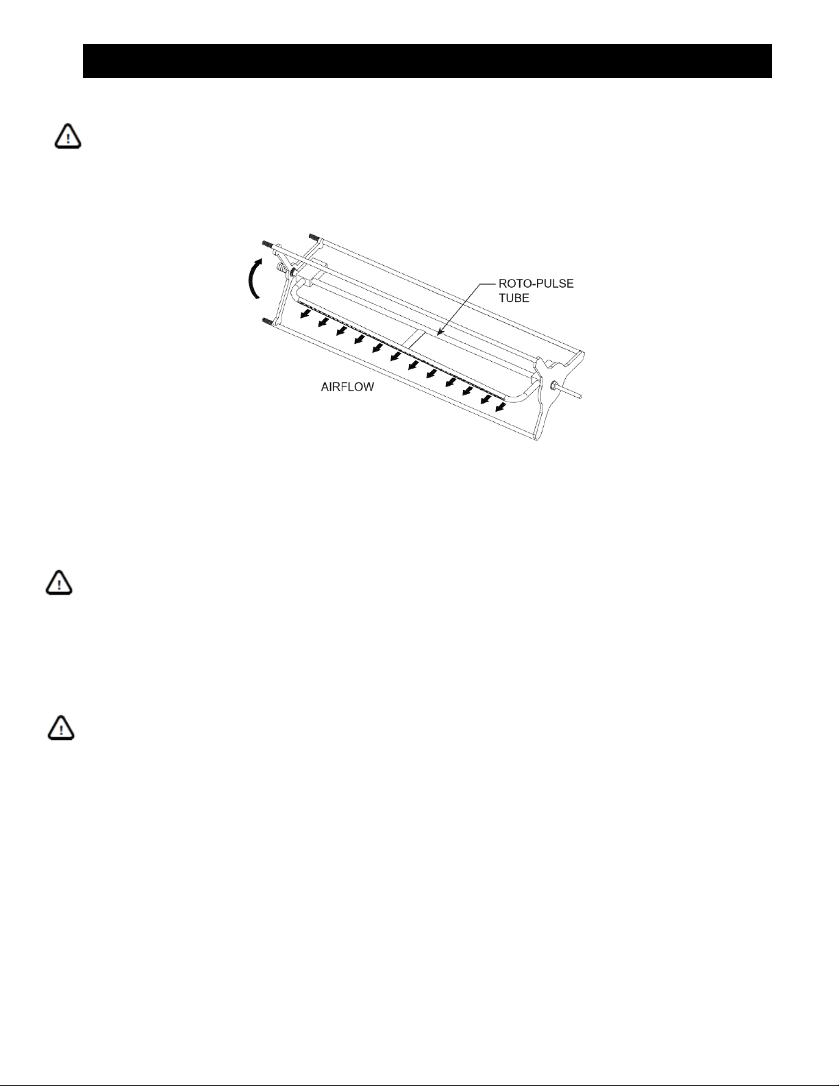
The Micro-Air Dust Collector is designed with the Roto-Pulse Cleaning System to clean the cartridge
filters. This system provides superior cleaning performance using a rotating tube with pre-drilled holes
(See FIG. 5). As the diaphragm valve opens, the Roto-Pulse tube rotates while air exits the holes, thus
providing the cleaning of the cartridge.
FIG. 5
1. For proper cleaning, the compressed air pressure should be regulated at 80 psi maximum.
2. During normal operation the Roto-Pulse cleaning system is factory set to clean 2 cartridge filters for a
period of .07 seconds every 5 seconds
3. Once the unit is turned off, the cleaning cycle will continue for a period of 2 minutes. Do not service the
filters until cleaning is completed.
CAUTION: Allow 20 minutes downtime before accessing filters. After-pulse system is
momentarily operational after unit is turned off.
4. The Roto-Pulse cleaning operation dislodges particles from the cartridges. Particles then fall down into
the collection tray.
ROTO-PULSE CLEANING TIMER ADJUSTMENTS:
CAUTION: Installation can cause exposure to live components. Disconnect electrical power
before proceeding with timer adjustments. Proper lockout / tag out procedures should be used.
1. Turn unit off via the stop switch and disconnect power.
2. Open the electrical box cover.
3. The timer control board is present at the factory to clean 2 cartridge filters every 5 seconds. This time
can be adjusted from 1 second to 999 seconds. To adjust this time press the select button on the timer
board until the off time LED is lit. Press the up/down buttons until the desired value is displayed and
press select to set the new value.
NOTE: Cleaning of the filters too often will decrease your level of performance. A certain level of dust
cake on the filters will improve the efficiency of the filter cartridges. You should try to maintain 1” W.C. of
pressure differential across the filters the time between cleaning pulses should be increased until this
can be achieved.
4. The timer control board is preset at the factory to have a cleaning pulse duration of .07 seconds. This
can be adjusted from .05 seconds to 600 seconds. To adjust this time press the select button on the

9
CAB MICRO AIR
timer board until the on time LED is lit. Press the up/down buttons until the desired value is displayed;
press select to set the new value.
NOTE: While this time can be adjusted we recommend you leave the “ON TIME” at the factory setting. If
less cleaning is needed you should increase the time between pulses as this means of reducing the
amount of cleaning. If more cleaning is needed you should decrease the amount of time between pulses.
Be aware, as the time between pulses is decreased for additional cleaning, this will increase your
compressed air consumption and create an additional load on your compressed air system.
5. Once adjustments have been made replace the electrical box cover and reconnect the power.
6. Start the unit and observe the new pulse settings and determine if additional adjustments are
necessary. If more adjustments are needed repeat the previous steps.
AFTER-PULSE CLEANING TIMER ADJUSTMENTS:
CAUTION: Installation can cause exposure to live components. Disconnect electrical power
before proceeding with timer adjustments. Proper lockout / tag out procedures should be used.
1. The unit is equipped with an After-Pulse Cleaning cycle. This cycle will continue to clean the cartridge
filters for a period of time after the unit is turned off.
2. The length of the After-Pulse operation is present at the factory for 100 seconds. This time can be
adjusted from 0 seconds to 999 seconds. To adjust this time press the select button until the off-time
LED is lit. Press and hold the select button for 3 seconds. Press the up/down buttons until the desired
value is displayed; press select to set the new value. The after-pulse operation can be disabled by
setting the time value to zero (0) seconds.

10
CAB MICRO AIR
HEPA/REGAIN PLENUM INSTALLATION PROCEDURE
This kit includes:
ITEM
PART NO.
DESCRIPTION
QTY.
1
P2543
¼” x 1 Self-Tapping Screw
8 ea.
2
37527-01
Exhaust Plate
1 ea.
3
P3649
4-Prong Knob
4 ea.
4
37580-01
HEPA/Regain Plenum Assembly
1 ea.
5
P2692
95% HEPA Filter
2 ea.
INSTALLATION:
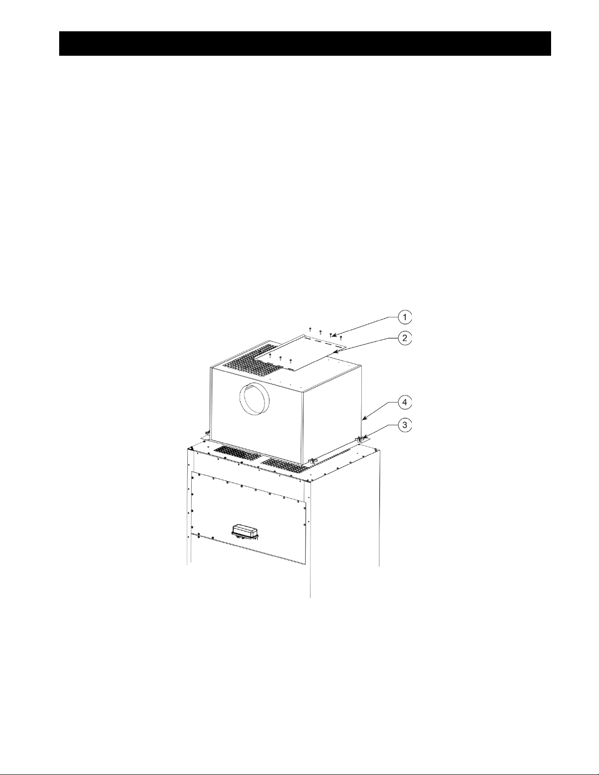
1. Remove HEPA/Regain plenum from skid and inspect for any possible damage incurred during shipping.
2. Place HEPA Filters (foam side down) on top of cabinet. NOTE: Center filters over grille on cabinet.
3. Place the HEPA/Regain Assembly over the filters. The duct opening should point towards the front of
the cabinet (See FIG. 6).
4. Use the four 4-Prong Knobs to fasten the HEPA/Regain assembly to the cabinet.
5. Connect duct work for Regain.
6. Adjust Exhaust Grille Plate to set Regain at the desired amount.
NOTE: Blocking more of the exhaust increases the amount of Regain Air.
FIG. 6
11
CAB MICRO AIR
SILENCER INSTALLATION PROCEDURE
This kit includes:
ITEM
PART NO.
DESCRIPTION
QTY.
1
P2543
¼” x 1 Self-Tapping Screw
8 ea.
2
37527-01
Exhaust Plate
1 ea.
3
P3649
4-Prong Knob
4 ea.
4
37590-01
Silencer Plenum Assembly
1 ea.
INSTALLATION:
1. Remove Silencer plenum from skid and inspect for any possible damage incurred during shipping.
2. Place the Silencer assembly over the exhaust plate. The duct opening should point towards the front of
the cabinet (See FIG. 7).
3. Use the four 4-Prong Knobs to fasten the Silencer assembly to the cabinet.
4. Connect duct work for Regain.
5. Adjust Exhaust Grille Plate to set Regain at the desired amount.
NOTE: Blocking more of the exhaust increases the amount of Regain Air.
FIG.7
12
CAB MICRO AIR
MAGNEHELIC KIT INSTALLATION PROCEDURE
This kit includes:
ITEM
PART NO.
DESCRIPTION
QTY.
1
38294-01
Magnehelic Mounting Bracket
1 ea.
2
P3755
0-10” W.C. Magnehelic Gauge
1 ea.
3
P3543
¼”-14 x 1” Self-Tapping Screw
4 ea.
4
P1848
¼” Clear Tubing
10 ft.
5
P2098
⅛” Male x ¼” Barb Fitting
1 ea.
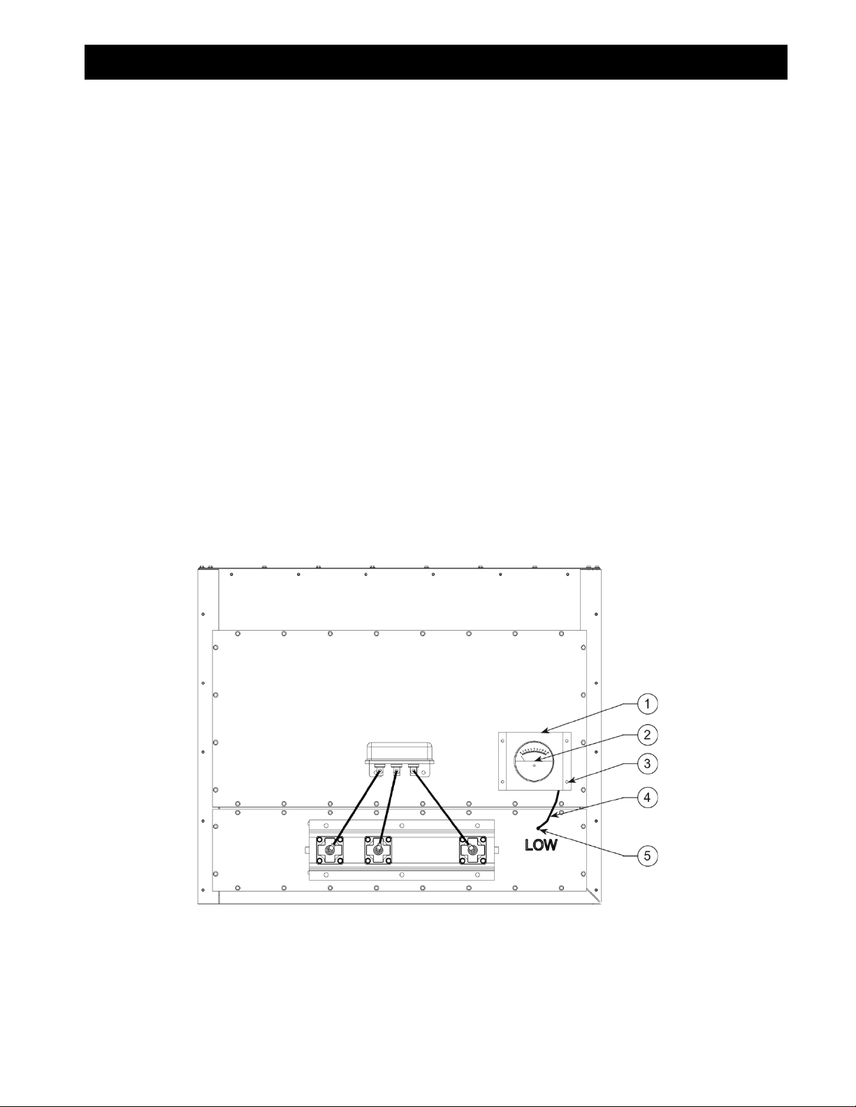
INSTALLATION:
1. Remove parts from package and inspect for any possible damage incurred during shipping.
2. Turn off Clean Air Booth and disconnect power to the unit.
3. Mount the Magnehelic Gauge into the Magnehelic Mounting Bracket and place the 2 male barb fittings
in the pressure ports located on the side of the Magnehelic Gauge.
4. Place the two pressure port plugs supplied with the Magnehelic Gauge on the 2 ports located on the
backside of the gauge.
5. Mount the bracket using the ¼” self-taping screws. The Magnahelic gauge may be mounted on any
surface within 10 ft. of the unit.
6. Using ¼” Clear Tubbing (Additional length can be purchased) connect the “LOW” pressure port on the
gauge to the clean air plenum. If the unit has multiple cabinets the gauge can be connected to any
cabinet.
7. Reconnect the power to the unit and start the Clean Air Booth.
8. Upon start up, the gauge should measure some amount of pressure drop (typically ½” W.C.). If no
pressure is measured, check connections for proper installation.
FIG. 8
13
CAB MICRO AIR
PHOTOHELIC KIT INSTALLATION PROCEDURE
This kit includes:
ITEM
PART NO.
DESCRIPTION
QTY.
1
38293-01
Photohelic Mounting Bracket
1 ea.
2
P3643
0-10” W.C. Photohelic Gauge
1 ea.
3
P3543
¼-14 x 1” Self-Tapping Screw
4 ea.
4
P1848
¼” Clear Tubing
10 ft.
5
P2098
⅛” Male x ¼” Barb Fitting
2 ea.
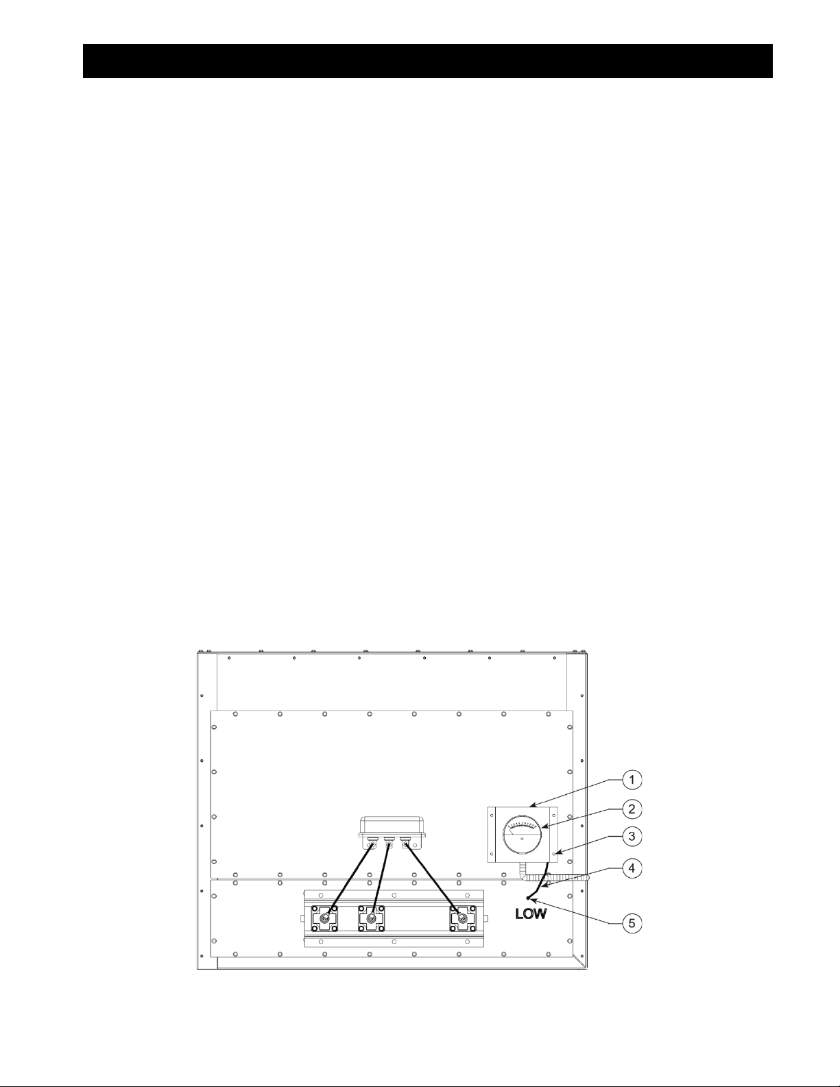
INSTALLATION:
1. Remove parts from package and inspect for any possible damage incurred during shipping.
2. Turn off Clean Air Booth and disconnect power to the unit.
3. Remove the plastic cover on the back of the Photohelic Gauge.
4. Mount the Photohelic Gauge into the Photohelic Mounting Bracket and place the 2 male barb fittings in
the pressure ports located on the side of the Photohelic Gauge.
5. Remove the cover from electrical box so that wiring diagram on back of cover can be used.
6. Remove two red wires that are connected to the Timer Board Pressure Switch Input and Auxilary
Contact.
7. Wire the Photohelic Guage as the electrical diagram shows in FIG. 18 (See PAGE 22) using the ¾”
conduit opening on the Photohelic (Wire and conduit supplied by others).
8. Replace the cover back onto the Photohelic Gauge and mount the bracket using the four ¼” self-
tapping screws.
9. Using ¼” clear tubing (Additional length can be purchased) connect the “LOW” pressure port on the
gauge to the clean air plenum.
10. You must replace the enable / disable switch located on the timer board to the “DISABLE” position. This
will disable the after-pulse mode of the timer board.
11. Replace the cover on the electrical box and reconnect the power to the unit.
12. The right set point dial of the gauge should be positioned at the filter differential set point you want the
Roto-Pulse system to be enabled. The left set point dial should be positioned at the filter differential set
point you want the Roto-Pulse system to be disabled.
FIG. 9

14
CAB MICRO AIR
SINGLE POWER PACK 230/460V MOTOR/BLOWER
FIG. 10
*NOTE: Units supplied with Photohelic option see FIG. 18 (Page 22). Refer to page 6 for installation
information.
*NOTE

15
CAB MICRO AIR
DUAL POWER PACK 230/460V MOTOR/BLOWER
FIG. 11
*NOTE: Units supplied with Photohelic option see FIG. 18 (Page 22). Refer to page 6 for installation
information.
*NOTE
16
CAB MICRO AIR
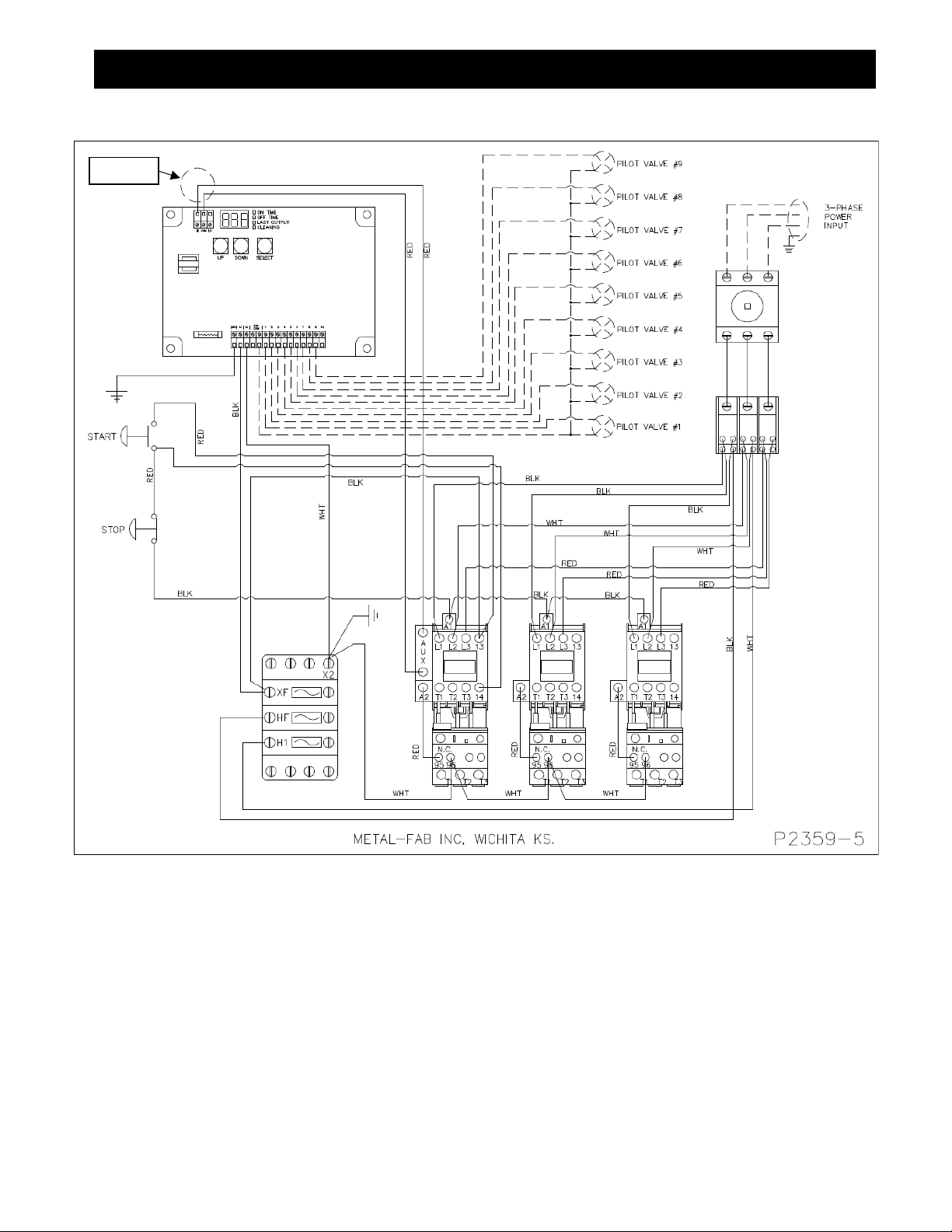
TRIPLE POWER PACK 230/460V MOTOR/BLOWER
FIG. 12
*NOTE: Units supplied with Photohelic option see FIG. 18 (Page 22). Refer to page 6 for installation
information.
*NOTE

17
CAB MICRO AIR
QUADRUPLE POWER PACK 230/460V MOTOR/BLOWER
FIG. 13
*NOTE: Units supplied with Photohelic option see FIG. 18 (Page 22). Refer to page 6 for installation
information.
*NOTE

18
CAB MICRO AIR
SINGLE POWER PACK 575V MOTOR/BLOWER
FIG. 14
*NOTE: Units supplied with Photohelic option see FIG. 18 (Page 22). Refer to page 6 for installation
information.
*NOTE
19
CAB MICRO AIR
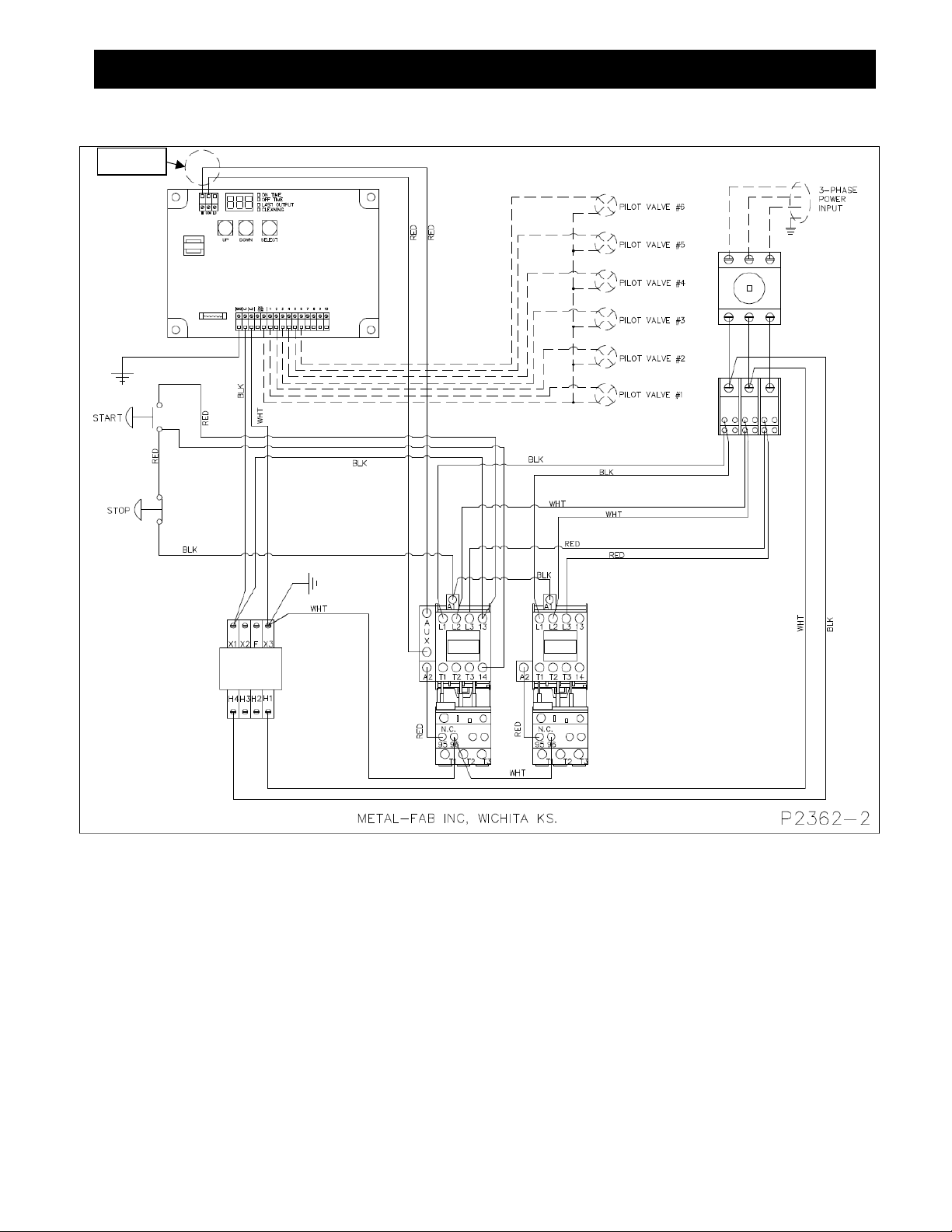
DOUBLE POWER PACK 575V MOTOR/BLOWER
FIG. 15
*NOTE: Units supplied with Photohelic option see FIG. 18 (Page 22). Refer to page 6 for installation
information.
*NOTE

20
CAB MICRO AIR
TRIPLE POWER PACK 575V MOTOR/BLOWER
FIG. 16
*NOTE: Units supplied with Photohelic option see FIG. 18 (Page 22). Refer to page 6 for installation
information.
*NOTE
Other manuals for CLEAN AIR BOOTH
1
Table of contents
Other MICRO-AIR Cleaning Equipment manuals


Popular Cleaning Equipment manuals by other brands


Suevia
Suevia 130.5011 EASYCLEANER Mounting instructions

i-MO
i-MO Öko 2000 user guide

unGer
unGer Hydro Power Ultra UNP01 operating instructions

Black & Decker
Black & Decker BHPC130 Original instructions

Uni-ram
Uni-ram UG5000E operating manual

Axi
Axi MTC HC-300 Installation, operating and maintenance manual