MICROENER N-DIN-MSG User manual

N-DIN-MSG (2044)
Doc. N° MO-0348-ING
Copyright 2010
(19)
Fw
RMB
360.11.0.x
FFP
360.6.0
Date
25.02.2008
Rev.
0
Pag.
1
of
31
MICROPROCESSOR
RELAY FOR
PERMANENT INSULATION SUPERVISION
OF D.C. SYSTEMS
TYPE
N-DIN-MSG
(for MSG-2044)
OPERATION MANUAL

N-DIN-MSG (2044)
Doc. N° MO-0348-ING
Copyright 2010
(19)
Fw
RMB
360.11.0.x
FFP
360.6.0
Date
25.02.2008
Rev.
0
Pag.
2
of
31
INDEX
1. General Utilization and Commissioning Directions ______________________________________________________ 3
1.1 - Storage And Transportation_______________________________________________________________________ 3
1.2 - Installation ____________________________________________________________________________________ 3
1.3 - Electrical Connection ____________________________________________________________________________ 3
1.4 - Measuring Inputs and Power Supply ________________________________________________________________ 3
1.5 - Outputs Loading________________________________________________________________________________ 3
1.6 - Protection Earthing _____________________________________________________________________________ 3
1.7 - Setting and Calibration___________________________________________________________________________ 3
1.8 - Safety Protection _______________________________________________________________________________ 3
1.9 - Handling______________________________________________________________________________________ 3
1.10 - Maintenance__________________________________________________________________________________ 3
1.11 - Waste Disposal of Electrical & Electronic Equipment __________________________________________________ 4
1.12 - Fault Detection And Repair ______________________________________________________________________ 4
2. General Characteristics _____________________________________________________________________________ 4
2.1 - Power Supply__________________________________________________________________________________ 5
2.2 –Operation and Algorithms ________________________________________________________________________ 5
2.2.1 –Reference Input Values ___________________________________________________________________________________ 5
2.2.2 –Input quantities__________________________________________________________________________________________ 5
2.2.2.1 –Frequency (Freq) of the test voltage _____________________________________________________________________ 5
2.2.2.2 –Current inputs_______________________________________________________________________________________ 5
2.2.2.3 –Voltage input _______________________________________________________________________________________ 5
2.2.2.4 –Earth Fault Resistance________________________________________________________________________________ 5
2.2.3 –Functions and Settings ___________________________________________________________________________________ 6
2.2.3.1 - 1RGs - First trip level for minimum insulation resistance______________________________________________________ 6
2.2.3.2 - 1RGd - First trip level for minimum insulation resistance______________________________________________________ 7
2.2.3.3 - 2RGs - Second trip level for minimum insulation resistance ___________________________________________________ 8
2.2.3.4 - 2RGd - Second trip level for minimum insulation resistance ___________________________________________________ 9
2.2.3.5 - OperMod - Operation Mode___________________________________________________________________________ 10
2.2.3.6 - Load Profile________________________________________________________________________________________ 11
2.2.3.7 - I.R.F. - Internal Relay Failure __________________________________________________________________________ 11
2.2.3.8 - MainComPar - Communication Parameters ______________________________________________________________ 12
2.2.4 –Self-diagnostic _________________________________________________________________________________________ 12
3. Relay Management ________________________________________________________________________________ 13
3.1 - Keyboard Operational Diagram ___________________________________________________________________ 14
4. Signalizations ____________________________________________________________________________________ 16
5. System Configuration Options ______________________________________________________________________ 17
5.1 - Main communication serial port on the Relay Main Body _______________________________________________ 19
5.2 –Communication Port on Front Face Panel __________________________________________________________ 20
5.3 –Communication between FFP and RMB____________________________________________________________ 21
6. Menu and Variables _______________________________________________________________________________ 22
6.1 –Real Time Measurements _______________________________________________________________________ 22
6.2 –RMB Selection________________________________________________________________________________ 22
6.3 –Instantaneous Measurements____________________________________________________________________ 22
6.4 –Operation Counters____________________________________________________________________________ 23
6.5 –Event Recording ______________________________________________________________________________ 24
6.6 –Programming / Reading the Relay Settings (R/W Setting) ______________________________________________ 25
6.6.1 –Communication Address _________________________________________________________________________________ 25
6.6.2 –Time/Date_____________________________________________________________________________________________ 25
6.6.3 –Rated Input Values______________________________________________________________________________________ 25
6.6.4 –Functions _____________________________________________________________________________________________ 26
6.7 –Commands __________________________________________________________________________________ 27
6.8 –Firmware –Info&Version________________________________________________________________________ 27
7. Password________________________________________________________________________________________ 28
7.1 - FFP Password ________________________________________________________________________________ 28
7.2 - Modbus Password _____________________________________________________________________________ 28
7.3 - MS-Com Password ____________________________________________________________________________ 29
8. Maintenance _____________________________________________________________________________________ 29
9. Power Frequency Insulation Test ____________________________________________________________________ 29
10. Connection Diagram______________________________________________________________________________ 30
11. Overall Dimensions ______________________________________________________________________________ 30
12. Electrical Characteristics__________________________________________________________________________ 31

N-DIN-MSG (2044)
Doc. N° MO-0348-ING
Copyright 2010
(19)
Fw
RMB
360.11.0.x
FFP
360.6.0
Date
25.02.2008
Rev.
0
Pag.
3
of
31
1. General Utilization and Commissioning Directions
Always make reference to the specific description of the product and to the Manufacturer's instruction.
Carefully observe the following warnings.
1.1 - Storage And Transportation
must comply with the environmental conditions stated on the product's instruction or by the applicable
IEC standards.
1.2 - Installation
must be properly made and in compliance with the operational ambient conditions stated by the
Manufacturer.
1.3 - Electrical Connection
must be made strictly according to the wiring diagram supplied with the Product, to its electrical
characteristics and in compliance with the applicable standards particularly with reference to human
safety.
1.4 - Measuring Inputs and Power Supply
carefully check that the value of input quantities and power supply voltage are proper and within the
permissible variation limits.
1.5 - Outputs Loading
must be compatible with their declared performance.
1.6 - Protection Earthing
When earthing is required, carefully check its efficiency.
1.7 - Setting and Calibration
Carefully check the proper setting of the different functions according to the configuration of the
protected system, the safety regulations and the co-ordination with other equipment.
1.8 - Safety Protection
Carefully check that all safety means are correctly mounted, apply proper seals where required and
periodically check their integrity.
1.9 - Handling
Notwithstanding the highest practicable protection means used in designing M.S. electronic circuits,
the electronic components and semiconductor devices mounted inside can be seriously damaged by
electrostatic voltage discharge which can be experienced when handling the cards.
The damage caused by electrostatic discharge may not be immediately apparent but the design
reliability and the long life of the product will have been reduced. The electronic circuits produced by
M.S. are completely safe from electrostatic discharge when housed in their case; dismounting the
cards without proper cautions expose them to the risk of damage and voids any guarantee and
relieves the Manufacture of any liability.
1.10 - Maintenance
Make reference to the instruction manual of the Manufacturer ; maintenance must be carried-out by
specially trained people and in strict conformity with the safety regulations.

N-DIN-MSG (2044)
Doc. N° MO-0348-ING
Copyright 2010
(19)
Fw
RMB
360.11.0.x
FFP
360.6.0
Date
25.02.2008
Rev.
0
Pag.
4
of
31
1.11 - Waste Disposal of Electrical & Electronic Equipment
(Applicable throughout the European Union and other European countries with separate collection
program). This product should not be treated as household waste when you wish dispose of it. Instead,
it should be handed over to an applicable collection point for the recycling of electrical and electronic
equipment. By ensuring this product is disposed of correctly, you will help prevent potential negative
consequence to the environment and human health, which could otherwise be caused by inappropriate
disposal of this product. The recycling of materials will help to conserve natural resource.
1.12 - Fault Detection And Repair
Internal calibrations and components should not be alterated or replaced.
For repair please ask the Manufacturer or its authorised Dealers.
Misapplication of the above warnings and instruction relieves the Manufacturer of any liability.
2. General Characteristics
N-DIN is a very versatile and complete Insulation Supervision Relay capable to control two independent
Systems. N-DIN relay is designed for surface mounting inside switchboards or panels on standard DIN-
EN 50022 rail, but its Front-Face-Panel (FFP) can be removed (by simply unscrewing the two fastening
screws) and flush mounted on the front panel of the Switchboard or on the front of a Power Control
Center bay. Connection between the MAIN RELAY BODY (MRB) mounted inside the switchboard and
the FFP mounted on the front panel, is made by a shielded double pair of twisted cables connected to
the relevant screw terminals available on the front of the MRB and on the back of the FFP.
The max distance between the two parts can be up to 2 meters; for longer distance the connection
cables must be laid in proper shielding conduits.
Connection between the two parts when assembled together is made by a plug-in connector provided
on each of the two parts.
This unique feature allows to have all controls and measurements available on the switchboard front
panel including local connection to a Lap-top PC, while the part connected to the Power Circuit remains
inside the panel closed to the C.Ts and to the control devices.
Moreover, where local display of measurements and data is not required, the RMB part can be used as
a stand alone relay featuring all protection and communication functions, saving the cost of the FFP.
A CANBUS output is also available to control optional slave expansion module and to transfer the
measurement to other apparatus.
Input currents are supplied from the AC injection Unit MSG to 2 current transformers measuring the
fault current.
Another input measures the test voltage applied to the supervised D.C. system by the AC injection
Unit.
The measuring inputs have the following ratings:
Rated continuous current
:
1A
Overload
:
2A continuous –50A for 1s
Ground Current measuring dynamic
:
(2-500)mA
Voltage measuring dynamic
:
(0.5-66)V
Three optoisolated, selfpowered digital inputs (D1, D2, RTD) are provided.
The digital inputs D1 and D2 are activated when their input terminals (6-8, 6-9) are shorted by a cold
contact (R3k); The input RTD is activated when the resistance connected across its terminals
below 2900.
Two output relays (R1, R2), each with one Normally Open 6A rating contact, are available.
Make electric connection in conformity with the diagram reported on relay's enclosure.
Check that input currents are same as reported on the diagram and on the test certificate.

N-DIN-MSG (2044)
Doc. N° MO-0348-ING
Copyright 2010
(19)
Fw
RMB
360.11.0.x
FFP
360.6.0
Date
25.02.2008
Rev.
0
Pag.
5
of
31
2.1 - Power Supply
The auxiliary power is supplied by a built-in module fully isolated an self protected.
Two options are available:
24V(-20%) / 80V(+15%) a.c.
80V(-20%) / 230V(+15%) a.c.
a)
-
b)
-
24V(-20%) / 90V(+20%) d.c.
90V(-20%) / 250V(+20%) d.c.
Before energising the unit check that supply voltage is within the allowed limits.
2.2 –Operation and Algorithms
2.2.1 –Reference Input Values
Display
Description
Setting Range
Step
Unit
Rsrvd
Reserved
Freq
50
Hz
System rated frequency
50
-
60
10
Hz
R_int
160
Internal resistance of MSG-2044 (the value is reported on front
face of MSG-2044 module)
1
-
1000
1
2.2.2 –Input quantities
2.2.2.1 –Frequency (Freq) of the test voltage
The relay can operate either with 50Hz or 60Hz.
The rated Frequency “ Freq “ must be set accordingly.
2.2.2.2 –Current inputs
The relay directly displays the r.m.s. “mA” value of the Fault Currents “ Is “ and “ Id” flowing in
each of the section under supervision. (In cable monitoring “Is” = fault current between Screen and
Ground, “Id” = Fault current between Conductor and Screen)
2.2.2.3 –Voltage input
The relay monitors the A.C. test voltage applied by the Main Injection Unit to the D.C. systems
under supervision. This voltage is also used as reference for measuring the Power Factor of the
injected current flowing through a fault as well as through the capacitance to earth of the D.C.
cables. The value of the Power Factor allows to discriminate between the Fault Current
(Resistive) and the normal leakage current (Capacitive).
2.2.2.4 –Earth Fault Resistance
Measurement range (2000 20000).
The relay measures the resistive component of the earth current and computes the fault
resistance of the two supervised circuits:
int_
cos R
sI
V
RGs
s
int_
cos R
dI
V
RGd
d
“V”
=
RMS value of voltage measured on
terminals 10-11.
“coss”
=
“V^Is” phase displacement
“Is”
=
RMS value of fault current shield to gnd.
“cosd”
=
“V^Id” phase displacement
“Id”
=
RMS value of fault current cable to shield.
“R_int”
=
Internal Resistance of MSG-2044
Where "R_int" is the internal resistance of MSG (normally 160).
On the Display the measurements of “cos s” and “cos d” are also available.
For angle “s” and “d” > 90°, the display show “cos = 0”.

N-DIN-MSG (2044)
Doc. N° MO-0348-ING
Copyright 2010
(19)
Fw
RMB
360.11.0.x
FFP
360.6.0
Date
25.02.2008
Rev.
0
Pag.
6
of
31
2.2.3 –Functions and Settings
2.2.3.1 - 1RGs - First trip level for minimum insulation resistance
FunctEnable
Status
Enable
[Disable / Enable]
Options
OUT
R1
[R1, R2, R1 + R2, None]
TripLev
1RGs
1000
(100 5000)
step
100
Timers
1ts
0.10
s
(0.1 100.00)
step
0.1
s
FunctEnable
:
[Disable]
=
Function disabled.
[Enable]
=
Function enabled.
OUT
:
Selection of the output relay operated at the end of trip time delay:
[R1]
=
Trip on output relay R1.
[R2]
=
Trip on output relay R2.
[R1+R2]
=
Trip on output relay R1+R2.
[None]
=
None.
1RGs
:
Minimum operation level
1ts
:
Trip time delay
Trip when
:
0 < RGs < [1RGs] and “Is Id”.
When the
function is tripped
:
Signalization
=
FFP
Led “Trip” flashing during time delay,
illuminated on trip.
RMB
Led “Trip” flashing during time delay,
illuminated on trip.
Output Relay
=
Is tripped (when programmed).
Event Recording
=
Is recorded.
Counter
=
Is incremented.
Function reset
when
:
Manual
(D1 open
R1)
(D2 open
R2)
=
“Reset” Push-button is pressed or via serial
communication, when the resistance is > of the
set threshold.
Automatic
(D1 closed
R1)
(D2 closed
R2)
=
The resistance is > of the set threshold.
Led reset when
:
Manual
=
Push-button “Reset” is pressed or via serial
command.

N-DIN-MSG (2044)
Doc. N° MO-0348-ING
Copyright 2010
(19)
Fw
RMB
360.11.0.x
FFP
360.6.0
Date
25.02.2008
Rev.
0
Pag.
7
of
31
2.2.3.2 - 1RGd - First trip level for minimum insulation resistance
FunctEnable
Status
Enable
[Disable / Enable]
Options
OUT
R1
[R1, R2, R1 + R2, None]
TripLev
1RGd
1000
(100 5000)
step
100
Timers
1td
0.10
s
(0.1 100.00)
step
0.1
s
FunctEnable
:
[Disable]
=
Function disabled.
[Enable]
=
Function enabled.
OUT
:
Selection of the output relay operated at the end of trip time delay:
[R1]
=
Trip on output relay R1.
[R2]
=
Trip on output relay R2.
[R1+R2]
=
Trip on output relay R1+R2.
[None]
=
None.
1RGd
:
Minimum operation level
1td
:
Trip time delay
Trip when
:
0 < RGs < [1RGd] and “Is Id”.
When the
function is tripped
:
Signalization
=
FFP
Led “Trip” flashing during time delay,
illuminated on trip.
RMB
Led “Trip” flashing during time delay,
illuminated on trip.
Output Relay
=
Is tripped (when programmed).
Event Recording
=
Is recorded.
Counter
=
Is incremented.
Function reset
when
:
Manual
(D1 open
R1)
(D2 open
R2)
=
“Reset” Push-button is pressed or via serial
communication, when the resistance is > of the
set threshold.
Automatic
(D1 closed
R1)
(D2 closed
R2)
=
The resistance is > of the set threshold.
Led reset when
:
Manual
=
Push-button “Reset” is pressed or via serial
command.

N-DIN-MSG (2044)
Doc. N° MO-0348-ING
Copyright 2010
(19)
Fw
RMB
360.11.0.x
FFP
360.6.0
Date
25.02.2008
Rev.
0
Pag.
8
of
31
2.2.3.3 - 2RGs - Second trip level for minimum insulation resistance
FunctEnable
Status
Enable
[Disable / Enable]
Options
OUT
R1
[R1, R2, R1 + R2, None]
TripLev
2RGs
200
(100 5000)
step
100
Timers
2ts
0.10
s
(0.1 100.00)
step
0.1
s
FunctEnable
:
[Disable]
=
Function disabled.
[Enable]
=
Function enabled.
OUT
:
Selection of the output relay operated at the end of trip time delay:
[R1]
=
Trip on output relay R1.
[R2]
=
Trip on output relay R2.
[R1+R2]
=
Trip on output relay R1+R2.
[None]
=
None.
2RGs
:
Minimum operation level
2ts
:
Trip time delay
Trip when
:
0 < RGs < [2RGs] and “Is Id”.
When the
function is tripped
:
Signalization
=
FFP
Led “Trip” flashing during time delay,
illuminated on trip.
RMB
Led “Trip” flashing during time delay,
illuminated on trip.
Output Relay
=
Is tripped (when programmed).
Event Recording
=
Is recorded.
Counter
=
Is incremented.
Function reset
when
:
Manual
(D1 open
R1)
(D2 open
R2)
=
“Reset” Push-button is pressed or via serial
communication, when the resistance is > of the
set threshold.
Automatic
(D1 closed
R1)
(D2 closed
R2)
=
The resistance is > of the set threshold.
Led reset when
:
Manual
=
Push-button “Reset” is pressed or via serial
command.

N-DIN-MSG (2044)
Doc. N° MO-0348-ING
Copyright 2010
(19)
Fw
RMB
360.11.0.x
FFP
360.6.0
Date
25.02.2008
Rev.
0
Pag.
9
of
31
2.2.3.4 - 2RGd - Second trip level for minimum insulation resistance
FunctEnable
Status
Enable
[Disable / Enable]
Options
OUT
R1
[R1, R2, R1 + R2, None]
TripLev
2RGd
1000
(100 5000)
step
100
Timers
2td
0.10
s
(0.1 100.00)
step
0.1
s
FunctEnable
:
[Disable]
=
Function disabled.
[Enable]
=
Function enabled.
OUT
:
Selection of the output relay operated at the end of trip time delay:
[R1]
=
Trip on output relay R1.
[R2]
=
Trip on output relay R2.
[R1+R2]
=
Trip on output relay R1+R2.
[None]
=
None.
2RGd
:
Minimum operation level
2td
:
Trip time delay
Trip when
:
0 < RGs < [2RGs] and “Is Id”.
When the
function is tripped
:
Signalization
=
FFP
Led “Trip” flashing during time delay,
illuminated on trip.
RMB
Led “Trip” flashing during time delay,
illuminated on trip.
Output Relay
=
Is tripped (when programmed).
Event Recording
=
Is recorded.
Counter
=
Is incremented.
Function reset
when
:
Manual
(D1 open
R1)
(D2 open
R2)
=
“Reset” Push-button is pressed or via serial
communication, when the resistance is > of the
set threshold.
Automatic
(D1 closed
R1)
(D2 closed
R2)
=
The resistance is > of the set threshold.
Led reset when
:
Manual
=
Push-button “Reset” is pressed or via serial
command.

N-DIN-MSG (2044)
Doc. N° MO-0348-ING
Copyright 2010
(19)
Fw
RMB
360.11.0.x
FFP
360.6.0
Date
25.02.2008
Rev.
0
Pag.
10
of
31
2.2.3.5 - OperMod - Operation Mode
The N-DIN-MSG is fitted with 2 output relays R1, R2 and 3 Digital Input D1, D2, D3:
-
R1
Can be controlled by any of the N-DIN-MSG functions according to
programming.
Reset can be operated by the reset button of the RMB and/or FFP and/or
by activation of the Digital Input “D1”.
-
R2
Can be controlled by any of the N-DIN-MSG functions according to
programming.
Reset can be operated by the reset button of the RMB and/or FFP and/or
by activation of the Digital Input “D2”.
-
D1
(Terminals 6-8)
Operates the reset after tripping cause is cleared
If “D1” terminals are permanently shorted, reset of “R1” after tripping takes
place automatically as soon as the tripping cause disappears.
-
D2
(Terminals 6-9)
Operates the reset after tripping cause is cleared
If “D2” terminals are permanently shorted, reset of “R2” after tripping takes
place automatically as soon as the tripping cause disappears.
-
D3
(Terminals 6-7)
Operates to lock-out the tripping of the relay function “RGs” and “RGd”
“Close” = Functions enabled – “Open” = Functions Disabled.
The menu “ OperMode “, includes three submenus (OPTIONS):
FunctEnable
Status
No Parameters
[No Parameters]
Options
Op_R1
N.E.
[N.E. –N.D.]
Op_R2
N.E.
[N.E. –N.D.]
Ctrl
Rsrvd
Reserved
TripLev
No Parameters
[No Parameters]
Timers
No Parameters
[No Parameters]
Op_R1
:
For selection of different operation modes of the Output Relay “R1”:
[N.E.]
=
Normally energized, deenergized on trip
[N.D.]
=
Normally deenergized, energized on trip
Op_R2
:
For selection of different operation modes of the Output Relay “R1”:
[N.E.]
=
Normally energized, deenergized on trip
[N.D.]
=
Normally deenergized, energized on trip
Ctrl
:
Reserved
[Local]
=
Not used in this version
[Remote]
=
Not used in this version

N-DIN-MSG (2044)
Doc. N° MO-0348-ING
Copyright 2010
(19)
Fw
RMB
360.11.0.x
FFP
360.6.0
Date
25.02.2008
Rev.
0
Pag.
11
of
31
2.2.3.6 - Load Profile
FunctEnable
Status
Enable
[Disable / Enable]
Options
No Parameters
[No Parameters]
TripLev
No Parameters
[No Parameters]
Timers
tLP
1.00
m
(1 650)
step
1
m
FunctEnable
:
[Disable]
=
Function disabled.
[Enable]
=
Function enabled.
tLP
:
Time interval
The Load Profile function, when activated and voltage is present (led ON illuminated), records the
value of current “ Is “, at every time interval “ tLP “.
Each record is complete with time/date tagging.
The memory buffer can store up to 100 records.
All the recorded data can be downloaded by the serial communication port and, with MSCom
interface program, they are displayed as time/current curve.
2.2.3.7 - I.R.F. - Internal Relay Failure
FunctEnable
Status
Enable
[Disable / Enable]
Options
OpIRF
NoTrip
[Trip / NoTrip]
OUT
None
[R1, R2, R1 + R2, None]
TripLev
No Parameters
[No Parameters]
Timers
No Parameters
[No Parameters]
FunctEnable
:
[Disable]
=
Function disabled.
[Enable]
=
Function enabled.
OpIRF
:
Selection of the output relay operated on tripping :
[Trip]
=
Trip output relay (when programmed)
[NoTrip]
=
No Trip
OUT
:
Selection of the output relay:
[R1]
=
Trip on output relay R1.
[R2]
=
Trip on output relay R2.
[R1+R2]
=
Trip on output relay R1+R2.
[None]
=
None.
The variable “ OpIRF “ available in the options of the “ IRF “ function, can be programmed to trip the
output relays same as the other protection functions (OpIRF = TRIP), or to only make the “ IRF “
signal led flashing without tripping the output relays (OpIRF = NoTRIP).

N-DIN-MSG (2044)
Doc. N° MO-0348-ING
Copyright 2010
(19)
Fw
RMB
360.11.0.x
FFP
360.6.0
Date
25.02.2008
Rev.
0
Pag.
12
of
31
2.2.3.8 - MainComPar - Communication Parameters
FuncEnab
No Param
No Parameters
Options
BaudR
9600
[9600 / 19200]
Mode
8,n,1
[8,n,1 / 8,o,1 / 8,e,1]
TripLev
No Param
No Parameters
Timers
No Param
No Parameters
BaudR
:
Baud Rate (Communication Speed)
Mode
:
Communication Parameters RS485 (terminals 4-5)
Note: Any change of this setting becomes valid at the next power on
2.2.4 –Self-diagnostic
The N-DIN incorporates a sophisticated self-diagnostic feature that continuously checks the
following elements:
A/D conversion
Checksum of the settings stored into E2P.
DSP general operation (Power, Routines, etc.)
Lamp test (only on manual test).
Any time Power is switched on, a complete test is run; then, during normal operation, the test is
run continuously and the checksum is done any time a parameter is stored into E2P.
If during the test any Relay Internal Failure (I.R.F) is detected:
If “ I.R.F. “ is programmed to “ Trip “the output relays are operated same as on tripping of any
protection function
If “ I.R.F. “ is programmed “NO Trip”, operation is memorized in the “ Event Records “.
If is also present a supervision circuit that, in case a transient anomaly of the DSP is detected,
produces a Reset to restore the normal operation and increments the counter HR.

N-DIN-MSG (2044)
Doc. N° MO-0348-ING
Copyright 2010
(19)
Fw
RMB
360.11.0.x
FFP
360.6.0
Date
25.02.2008
Rev.
0
Pag.
13
of
31
3. Relay Management
The relay can be totally managed either locally by the 4 key buttons and the LCD display or remotely
either by a PC connected to the serial port on Front Face (RS232) and/or by the main serial
communication bus RS485 connected to the RMB.
The 2 line x 16 characters LCD display shows the available information.
Key buttons operate according to the flow-chart herebelow.

N-DIN-MSG (2044)
Doc. N° MO-0348-ING
Copyright 2010
(19)
Fw
RMB
360.11.0.x
FFP
360.6.0
Date
25.02.2008
Rev.
0
Pag.
14
of
31
3.1 - Keyboard Operational Diagram

N-DIN-MSG (2044)
Doc. N° MO-0348-ING
Copyright 2010
(19)
Fw
RMB
360.11.0.x
FFP
360.6.0
Date
25.02.2008
Rev.
0
Pag.
15
of
31

N-DIN-MSG (2044)
Doc. N° MO-0348-ING
Copyright 2010
(19)
Fw
RMB
360.11.0.x
FFP
360.6.0
Date
25.02.2008
Rev.
0
Pag.
16
of
31
4. Signalizations
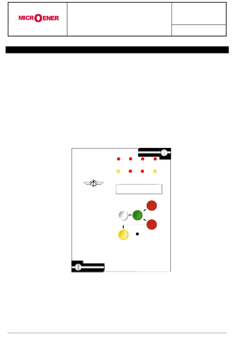
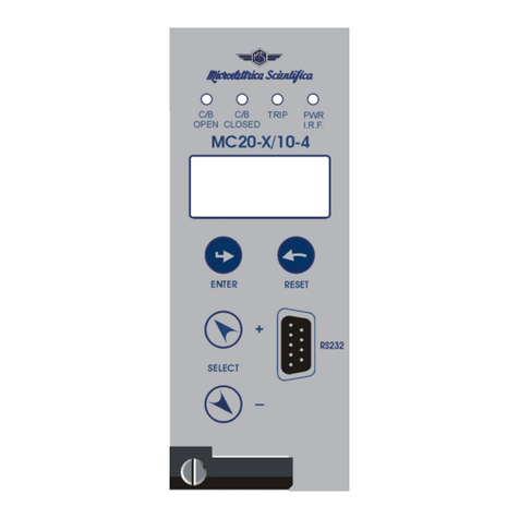
Four signal leds are available on the removable Front Face Panel (FFP):
a)
Green
LED
PWR/
I.R.F.
Illuminated during normal operation when Power Supply is ON.
Flashing when a Relay Internal Fault is detected.
b)
Yellow
LED
TRIP
Flashing when a timed function has started to operate.
Illuminated when any function was tripped, reset takes places either by
pressing the reset button.
c)
Red
LED
ON
Illuminated when the input voltage is present.
d)
Green
LED
OFF
Illuminated when the input voltage is not present.
The reset button on FFP, resets the Output Relays and the Trip Signal Led after tripping.
Other two leds are provided on the Relay Main Body (RMB) visible when the front face is removed
a)
Green
LED
PWR/
I.R.F.
Illuminated during normal operation when Power Supply is ON.
Flashing when a Relay Internal Fault is detected.
b)
Red
LED
TRIP
Flashing when a timed function has started to operate.
Illuminated when any function was tripped until Reset button is pressed.
c)
Button
RESET
To Reset after tripping the output relays and the trip signal led.

N-DIN-MSG (2044)
Doc. N° MO-0348-ING
Copyright 2010
(19)
Fw
RMB
360.11.0.x
FFP
360.6.0
Date
25.02.2008
Rev.
0
Pag.
17
of
31
5. System Configuration Options
The relay N-DIN is constituted of two independent parts (RMB and FFP) that can be either used as
stand-alone device or combined in different ways.
The FFP can be directly plug-in and fixed by two screws on one RMB or it can be remotely connected to
one or more (up to 31) RMB by the relevant terminals.
It is recommended to power-off the RMB modules before plug-in/out or connecting the FFP.
1) Use of one “ RMB + FFP “ assembly for each protection unit.
The FFP module can be mounted either directly on its RMB module or on the front panel of the board
connected to the RMB by four wires (terminals A, B, +, 0).
2) Use of up to 31 RMB modules managed by only one FFP.

N-DIN-MSG (2044)
Doc. N° MO-0348-ING
Copyright 2010
(19)
Fw
RMB
360.11.0.x
FFP
360.6.0
Date
25.02.2008
Rev.
0
Pag.
18
of
31
3) Use of RMB modules only without FFP.
4) combination of configuration 1 –2 –3.

N-DIN-MSG (2044)
Doc. N° MO-0348-ING
Copyright 2010
(19)
Fw
RMB
360.11.0.x
FFP
360.6.0
Date
25.02.2008
Rev.
0
Pag.
19
of
31
5.1 - Main communication serial port on the Relay Main Body
This port is accessible via the plug-in terminals (4 - 5) provided on the RMB.
It is used for connection to a serial bus interfacing up to 31 - N-DIN units with the Central Supervision
System (SCADA, DCS, ecc).
The serial bus is a shielded pair of twisted cables connecting in parallel (Multi Drop) the different units
(slaves) by the relevant terminals available on the “ Relay Main Body “.
The physical link is RS485 and the Communication Protocol is MODBUS/RTU:
The configuration is selectable (see § MainComPar).
Baud Rate
:
9600/19200 bps
9600/19200 bps
9600/19200 bps
Start bit
:
1
1
1
Data bit
:
8
8
8
Parity
:
None
Odd
Even
Stop bit
.
1
1
1
Note: any change of this setting became valid at the next power on.
Each relay is identified by its programmable address code (NodeAd) and can be called from the P.C.
A dedicated communication software (MSCom) for windows 95/98/XP/NT4 SP3 (or later) is available.
Please refer to the MSCom instruction manual for more information.
Maximum length of the serial bus can be up to 200m.
For longer distance and for connection of up to 250 Relays, optical interconnection is recommend.
(please ask Microelettrica for accessories)

N-DIN-MSG (2044)
Doc. N° MO-0348-ING
Copyright 2010
(19)
Fw
RMB
360.11.0.x
FFP
360.6.0
Date
25.02.2008
Rev.
0
Pag.
20
of
31
5.2 –Communication Port on Front Face Panel
This port is used for communication through the Front Face Panel (FFP) between a local Lap-top PC
and any of the RMB connected to the FFP.
The physical link is RS232 by the standard female 9-pin D-sub connector available on the Front Face
Panel. Via this Port complete Relay management and data acquisition is possible.
When this serial Port is connected, the Front Face Panel is bypassed, but still in communication with
the Relay Main Bodys connected.
The connection between the “ FFP “ and the “ RMB ” (when FFP is removed) is made by four shielded
twisted cables connected to the relevant terminals available on the back of the “ FFP “ and on the front
of the “ RMB “. All additional RMBs only need a pair of shielded twisted cables.
The terminals on the “ RMB “front can also be used for direct connection to a local Lap-top PC
through a RS485/232 converter without going through a FFP.
Table of contents
Other MICROENER Relay manuals
MICROENER
MICROENER ELR-3B User manual
MICROENER
MICROENER MM30-W User manual
MICROENER
MICROENER ELRC-1 User manual
MICROENER
MICROENER MG30 User manual

MICROENER
MICROENER IM3G-VX User manual
MICROENER
MICROENER IM30-SA User manual
MICROENER
MICROENER MC3V-X/10-4 User manual
MICROENER
MICROENER IM30-GLF User manual

MICROENER
MICROENER IM30-DK User manual

MICROENER
MICROENER ULTRA Series User manual

