1
2
3
4
5
8
9
6
7
10
a
b
c
d
info@microener.com
+33(0)1 48 15 09 09
MANUEL D'UTILISATION
INSTRUCTION MANUAL - MANUALE
ISTRUZIONI - MANUAL DE
INSTRUCCIONES – BETRIEBSANLEITUNG
IM250-IUEDFV1..4
MU N°:
15LA2101440
Rev. : A
Page 1 sur 2
ELRC-1
Relais différentiel de défaut à la terre
Earth Leakage Relay
Relè differenziale di terra
Relé diferencial
Erdschlussrelais
FR
Légende
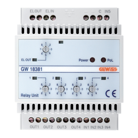
1) Potentiomètre de réglage de la temporisation de fonctionnement;
2) Potentiomètre de réglage du seuil de fonctionnement;
3) Commutateurs glissants pour la sélection des constantes:
- réarmement Automatique ou Manuel selon position (a) : 1/0;
- sélection de la dynamique du temps de fonctionnement:
K = 1 pour commutateur (b) en position 0;
K = 10 pour commutateur (b) en position 1;
- sélection de la dynamique du seuil de fonctionnement ;
K = 0.1 pour commutateurs (c-d) en position 0;
K = 1 pour commutateur (c) en pos. 1 et (d) en pos. 0;
K = 10 pour commutateurs (c-d) en pos. 1;
4) Bouton-poussoir d’essai;
5) Bouton-poussoir de réarmement;
6) Signalisation de présence tension d’alimentation auxiliaire (LED VERT);
7) Lampe de signalisation d’intervention (LED ROUGE);
8) Bornes alimentation auxiliaire
9) Bornes relais de sortie
IMPORTANT: Sur la version « fonctionnement à manque, la bobine de
déclenchement (Ba) doit être connectée aux bornes 4-5.
UK
legend
1) Delay adjustment potentiometer;
2) Tripping current adjustment potentiometer;
3) Sliding contact switch for selection of constants:
- automatic resetting with switch (a) in pos.1;
- selection of constant for delay rating:
K = 1 for switch (b) in pos. 0;
K = 10 for switch (b) in pos. 1;
- selection of constant for current rating:
K = 0.1 for switch (c) and (d) in pos. 0;
K = 1 for switch (c) in pos. 1 and switch (d) in pos. 0;
K = 10 for switches (c) and (d) in pos. 1;
4) Test push-button;
5) Manual reset push-button;
6) Signalling lamp of existing auxiliary voltage supply (green LED);
7) Signalling lamp of tripped relay (red led);
8) Terminals for auxiliary supply;
9) Relay output terminals;
IMPORTANT: In the version with excited relay (fail safe), the coil (Ba) must
be connected at the terminal 4-5.
IT
legenda
1) Potenziometro di regolazione tempo d’intervento;
2) Potenziometro di regolazione corrente di guasto a terra;
3) Commutatore a slitta per la scelta delle costanti:
- riarmo automatico con commutatore (a) in posizione 1;
- scelta costante per taratura di tempo:
K = 1 commutatore (b) in posizione 0;
K = 10 commutatore (b) in posizione 1;
- scelta costante per taratura di corrente:
K = 0.1 per commutatori (c-d) in posizione 0;
K = 1 per commutatore (c) in posizione 1 e commutatore (d) in
posizione 0;
K = 10 per commutatori (c) e (d) in posizione 1;
4) Pulsante per prova;
5) Pulsante per riarmo manuale;
6) Lampada di segnalazione presenza di alimentazione ausiliaria (LED verde);
7) Lampada di segnalazione di relè intervenuto (LED rosso);
8) Morsetti per alimentazione ausiliaria;
9) Morsetti di uscita relè;
IMPORTANTE: Nella versione con relé eccitato (sicurezza positiva) la
bobina (Ba) deve essere connessa hai morsetti 4-5..
ES
legenda
1) Potenciómetro de regulación tiempo de disparo.
2) Potenciómetro de regulación intensidad de fuga.
3) Micro interruptor para la elección de las constantes:
- Rejuste con interruptor automático (a) en pos.1
- tiempo:
K = 1 para micro (a) en posición 0;
K=10 para micro(a) en posición 1;
- Intensidad:
K=0,1 para micro (b-c) en posición 0;
K= 1 para micro(b) en posición 1 y (c) en posición 0;
K=10 para micro (c-b) en posición 1
4) Pulsador de prueba.
5) Pulsador de rearme manual.
6) Lámpara de señalización presencia de tensión auxiliar (LED verde).
7) Lámpara de señalización de relé disparado (LED rojo).
8) Terminales de alimentación auxiliar;
9) Terminales terminales de salida Relé
IMPORTANTE: En la version con relé excitado (seguridad positiva) la
bobina (Ba) debe estar conectada a los terminales 4 y 5.
DE
legende
1) Potentiometer für die Einstellung der Auslösezeit.
2) Potentiometer für die Einstellung des Auslösestroms.
3) Mikroschalter für die Auswahl der Konstante:
- Automatischen Zurücksetzen mit Mikroschalter (a) auf Position 1;
- Zeit:
K = 1 mit Mikroschalter (b) auf Position 0;
K=10 mit Mikroschalter (b) auf Position 1;
- Strom:
K=0,1 mit Mikroschalter (c-d) auf Position 0;
K= 1 mit Mikroschalter (c) auf Position 1und (d) auf Position 0;
K=10 mit Mikroschalter (c-d) auf Position 1
4) Testdrucktaste.
5) Manuelle Reset-Taste.
6) Signallampe für Hilfsspannung (grüne LED-Anzeige).
7) Signallampe für ausgelöstes Relais (rote LED-Anzeige).
8) Klemmen für Hilfsspannung
9) Klemmen für Ausgangsrelais
WICHTIG: In der Version mit erregtem Relais (Fehlersicherheit), die Spule
(BA) mit den Klemmen 4-5 verbinden.
