Micron T 2444A User manual

Altronics Pty. Ltd. Sydney Melbourne Perth Brisbane Adelaide
www.altronics.com.au
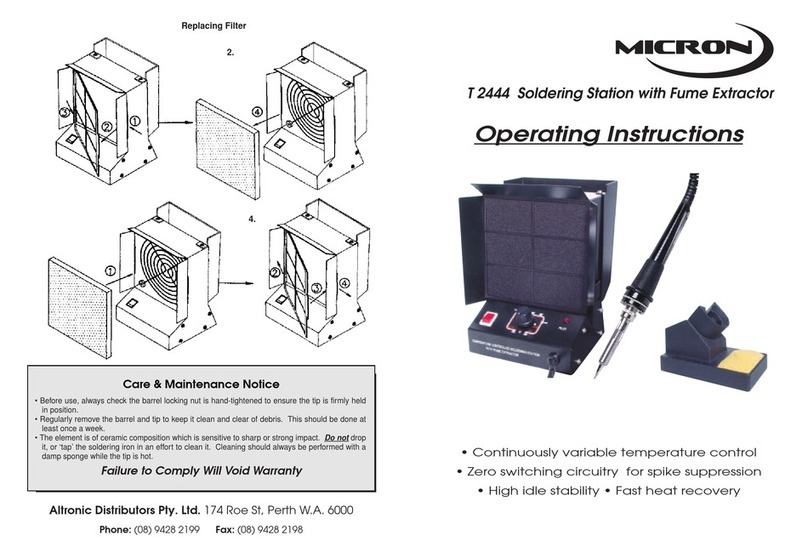
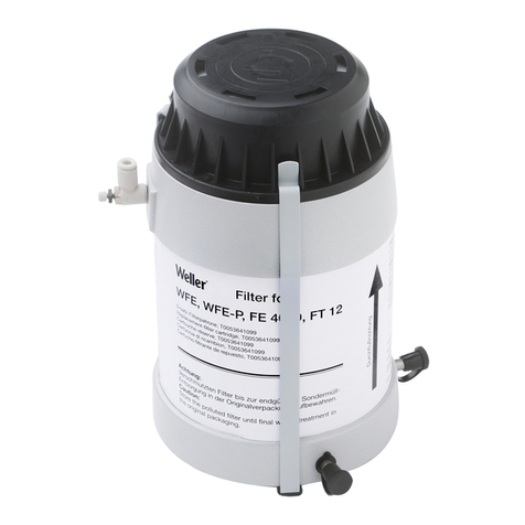
Replacing Filter
2.
4.
Care & Maintenance Notice
• Before use, always check the barrel locking nut is hand-tightened to ensure the tip is firmly held
in position.
• Regularly remove the barrel and tip to keep it clean and clear of debris. This should be done at
least once a week.
• The element is of ceramic composition which is sensitive to sharp or strong impact. Do not drop
it, or ‘tap’ the soldering iron in an effort to clean it. Cleaning should always be performed with a
damp sponge while the tip is hot.
Failure to Comply Will Void Warranty
7

T 2444A
60W Soldering Station
with Fume Extractor
Operating Instructions
• Continuously variable temperature control
• Zero switching circuitry for spike suppression
• High idle stability • Fast heat recovery
• All metal construction • High performance ball bearing fan
• “Active Carbon” filter • ESD safe

Micron T 2444A Soldering Station
Congratulations on purchasing the Micron T 2444A Temperature Controlled
Soldering Station with Fume Extractor. Its compact size ensures that the work surface
is not cluttered up and it is easily positioned to ensure maximum effect.
Product Description:
This specialised soldering station has been developed to meet the present and
future needs of the electronic production industry. The all metal construction
coupled with the high performance ball bearing fan makes this ideally suited to
production line assembly, service centres, work benches, colleges etc.
It incorporates electronic circuitry which enables the user to change the tip
temperature from 250°C through 450°C without changing the tip or heating element.
The transformer-less power supply ensures excellent temperature stability by
accurately monitoring the minute changes in element resistance which occur in
proportion to temperature variations.
The electronic opto isolated “zero voltage” switching used protects voltage and
current sensitive components, such as CMOS devices, against transient voltage
spikes, which can be caused by switching the power or heater on/off, or other
environmental conditions.
The ceramic heating element is designed specially to bring the element
temperature up to approximately 450°C at full setting in under one minute. The
higher temperature allows for reserve heat to ensure ultrafast recovery at lower
temperature settings.
The high insulation of the ceramic heating element is over 100Mohm and the tip is
grounded to ensure leakage is less than 0.4 millivolts.
Inside the box:
• T 2444A • AC Power Cord • Instruction Manual • Soldering Handle Stand
Specifications:
Input Power: ..................................................................................................... 220-240VAC
Solder Station Wattage: ................................................................................................. 60W
Temperature Range: ........................................................................................ 250 - 450°C
Tip Leakage: .............................................................................................................. < 2mV
Tip To Ground Resistance: .................................................................................... < 0.1ohm
Stability @ Idle: ............................................................................................................ ±5°C
Fan Wattage: ................................................................................................................ 20W
Maximum Air Volume: ...................................................................................... 95/115 CFM
Outer Dimensions: ...................................................................... 162W X 200H X 120D mm
Weight (Excluding AC Cord): ............................................................................... 1500grams
Replacement Filter (130mm2): .................................................................................. T 1291
1
Micron T 2444A Soldering Station
2
Operating Instructions:
1 Place the soldering iron into the stand provided.
2 Plug in the power cable and slide the switch to ‘on’ position then LED lamp will be
on. The extractor fan will start automatically.
3 Set the temperature by rotating temperature control knob on the front panel to
the temperature desired.
4 Always keep the sponge wet.
5 Set the temperature control knob to the minimum when temporarily not using the
soldering station, thereby extending the life of heater and tip.
Working Temperature:
A low iron temperature will slow the flow of solder. A high temperature will burn
the flux in the solder, which in turn will emit a heavy white smoke, that can result in
a dry joint or damage to the PCB. When the tip working temperature is within the
correct parameters suited to the particular solder being used, a good joint is assured.
The most common solder alloy used in the electronics industry is 60% tin, 40% lead
(60/40).The tip working temperature of solder is detailed below and can vary slightly
from manufacturer to manufacturer.
Melting point: ............................................................................................................ 215°C
Normal Operation ..................................................................................................... 320°C
Production Line Operation ......................................................................................... 380°C
Desoldering Operation for Small Joint ........................................................................ 320°C
Desoldering Operation for Larger Joint ....................................................................... 400°C
NOTE: Lead-free solder alloys require a working temperature of 30°C higher than the
previous generation of electrical soldering.
Caution: Temperatures above 400°C should not be used for normal soldering
purposes; however temperatures above 400°C may be used for short periods when
required.
Possible causes of tip not tinning-
1. Tip temperature higher than 400°C
2. Working surface is not well tinned during idling periods
3. Lack of flux in soldering, wicking, repairing and touch-up etc. operations.
4. Wiping tip on high sulphur content sponge, dirty or dry sponge and/or rags.
5. Contacting with organics, plastic resins, silicone grease, and other chemicals.
6. Impurities in solder and/or low tin content.

Micron T 2444A Soldering Station
3
Care of Tips:
Important: Remove the tip and clean after every use of at least once a week, remove
any loose build up in the barrel or tip to prevent tip seizing. The tips supplied are iron
plated copper and if used properly will last a long time.
1. Always keep tip tinned before returning the iron to the holder prior to switching
off or storing for any period of time, wipe only before using.
2. Don’t keep iron set at high temperatures for long period as this will break down
the surface plating of the tip.
3. Don’t use excessive pressure on a tip or rub a tip on a joint during the making of a
joint as it does not improve heat transfer and damages the tip.
4. Never clean tip with abrasive materials or files.
5. Don’t use fluxes containing chloride or acid. Use only rosin or activated rosin fluxes.
6. If any oxide film does form, this can be cleaned by carefully rubbing with a “600-
800 grit” emery cloth, or isopropyl alcohol and re-heat. Re-tin the tip using rosin
core solder.
New Tip:
Care for the new tip according to the following procedures for longer tip life.
1 Set temperature at 250°C, then turn main power switch “on”.
2 Flood the tinned surfaces with rosin core solder after reaching 250°C.
3 Set to desired temperature after warming at 250°C for three minutes.
4. The iron is ready for use after reaching the pre-set desired temperature.
Maintenance:
Tip Replacement and Dressing
1 Turn off the iron and disconnect the mains plug from the mains supply.
2 Allow the iron to cool completely before attempting disassembly.
3 Unscrew the knurled nut, and remove the barrel assembly.
Note: the ceramic heating element may be broken by careless handling.
4 Remove the tip, and blow out any accumulated dust. Avoid getting dust in your
eyes.
5 Replace the tip and screw back the retaining knurled nut and barrel assembly
using only firm hand pressure to tighten. Do not use pliers.
Filter Replacement:
Under normal operating conditions the filter should be replaced once a month
or when excessive dust has obviously adhered to or discoloured the filter. Failure to
change the filter regularly will directly affect the absorption capacity and effectiveness

Micron T 2444A Soldering Station
4
of the fume extractor.
Follow the directions on the back page to replace the filter.
Replacement filter part number: T 1291
General Cleaning:
The outer case of iron or station may be cleaned with a damp cloth using small
amounts of liquid detergent.
Never douse the unit in liquid or allow any to enter the case of the station. Never
use any solvent to clean the case.
WARNING
• The appliance is not intended for use by young children or infirm persons without
supervision.
• Young children should be supervised to ensure that they do not play with the
appliance.
• The soldering iron must be placed on its stand when not in use.
Spare Parts:
T-2444AA Heater element
T-2444B Barrel to suit
T-2444C Collar nut for barrel
T-2444D Silicon cable
T 2412 0.8mm conical tip
T 2413 1.6mm chisel tip
T 2414 3.2mm chisel tip
T 1291 Replacement fil
Table of contents
Other Micron Soldering Gun manuals

Micron
Micron T 2443 User manual

Micron
Micron T 2052 User manual

Micron
Micron T 1287 User manual

Micron
Micron T 2444 User manual

Micron
Micron T 2460A User manual

Micron
Micron T 1260 User manual

Micron
Micron T 2418 User manual

Micron
Micron 300W User manual

Micron
Micron T 2040 User manual

Micron
Micron T 2438 User manual