manuals.online logo
Brands
  1. Home
  2. •
  3. Brands
  4. •
  5. MicroNet
  6. •
  7. Switch
  8. •
  9. MicroNet SP6008P User manual

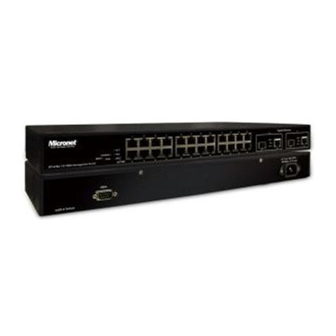
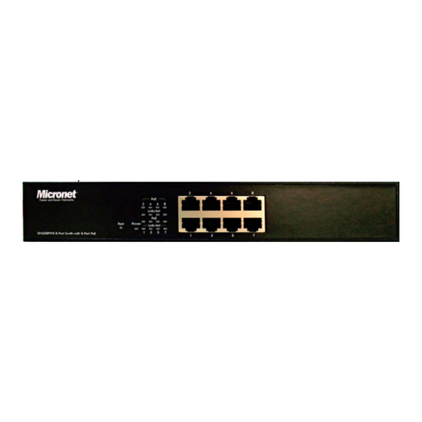
MicroNet SP6008P User manual

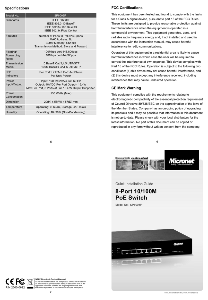
Communicate via
P/N 2300-0749
Quick Installation Guide
Model No.: SP6008P
8-Port 10/100M PoE Switch
6
5
7
CE Mark Warning
This equipment complies with the requirements relating to
electromagnetic compatibility of the essential protection requirement
of Council Directive 89/336/EEC on the approximation of the laws of
the Member States. Company has an on-going policy of upgrading
its products and it may be possible that information in this document
is not up-to-date. Please check with your local distributors for the
latest information. No part of this document can be copied or
reproduced in any form without written consent from the company.
WEEE Directive & Product Disposal
At the end its serviceable life ,this product should not be treated
as household or general waste. It should be handed over to the
applicable collection point for the recycling of electrical and
electronic equipment, or returned to the supplier for disposal.
www.micronet.com.tw
Specifications
SP6008P
Model No.
Standards
Features
Pin Assignment
and Polarity
LED Indicators
PoE Power
Consumption
Power
Dimension
Weight
Environment
IEEE 802.3af/at PoE
IEEE 802.3 10 BaseT
IEEE 802.3u 100 BaseTX
IEEE 802.3x Flow Control
Number of Ports: 8 PoE/PSE ports
MAC Address: 2k
Buffer Memory: 768 bits
Transmission Method: Store and Forward
1/2 (+), 3/6 (-)
Per Port: Data, PoE
Per Unit: Power, PoE Max. A/B
DC Per Port Output- 30W Max on Port,
8 Ports at Full 15.4 W Output Supported
120 Watts (Max)
100~240VAC
44.5(H) x 280(W) x 179(D)mm
1.61 Kg
O
Operating Temperature : 0~50 C
Storage Temperature : -40 C to 70 C
Network Speed Cable Type
10M
100M
Max. Length
Cat. 3,4,5,5e UTP/STP
Cat. 5e,6 UTP/STP
100 meters
100 meters
Connect To Ground
Connecting the switch to ground protects against lightning
over-voltage and over-current of the switch, which is also a
necessary measure to protect the body from electric shock.
In different environments, the switch may be grounded differently.
The following instructs you to connect the switch to ground through
the power cord. Connect the switch to ground in the best way
according to your specific operating environment.
Connect To Ground Through The Power Supply
If the switch is installed in a normal environment, it can be grounded
through the PE (Protective Earth) wire of the AC power supply, as
shown in the following figure 4
Connecting Network Device
For cable selection, refer to the following table:
The setup of the switch can be performed using the following steps:
Step 1: Connect the Power Cord to SP6008P and then to a power
outlet.
Step 2: Connect a RJ-45 Ethernet cable from IEEE802.3af/802.3at
compliant devices (PD) to an available PoE port of SP6008P.
Note:
Port 1 to Port 8 are used for connecting to PD or PoE splitter for
end
devices.
Introduction
The SP6008P supports IEEE 802.3af/at standard for Power over
Ethernet (PoE) with the maximum power delivery up to 120 Watts.
That makes it suitable to various applications that demand for
remote power feeding and meet high level requirement for power.
SP6008P is totally equipped with 15.4Watts per port or max. 30
Watts for one port, which effectively helps allocate power for
connected multiple devices and enhances network management.
Key Features
8 Port 10/100M Nway (Auto-negotiation) Switch
Supports IEEE 802.3az Energy-Efficient Ethernet
Supporting the power 15.4W per port or max. 30W for one port
Auto-learn of networking configuration
Auto-detect full/half-duplex modes for any port
Store-and-Forward switching methods
IEEE 802.3x flow control for full-duplex and back-pressure flow
control for half-duplex
PoE total power budget 120W for all PoE ports
Package Contents
Before you start installing SP6008P, please verify the following
package contents:
SP6008P 10/100M PoE Switch
Quick Installation Guide
Power Cord
Rackmount Kit
4
3
1 2
Tour of the System
Front Panel
LED indicators
Back Panel
Power Cord Connector
Hardware Installation
Desktop Installation
To install the switch on the desktop, follow these steps:
1. Set the switch on a flat surface strong enough to support the
entire weight of the switch with all fittings.
2. Remove the adhesive backing papers from the rubber feet.
3. Turn the switch over and attach
the supplied rubber feet to the
recessed areas on the bottom
at each corner of the switch.
4. Upturn the switch and set in the desired location, making sure
there is enough ventilation space on all sides for proper air flow
5. Connect the switch to a power source with the provided power
cord
Rack Installation
1. Secure the supplied rack-mounting brackets to each side of the
switch with supplied screws, as illustrated in the following figure 2
2. Use suitable screws (not provided) to secure the brackets to the
rack, as illustrated in the figure 3
LED indicators
For definitions of LED indicators, please refer to the following table:
LED Status
Power
Indication
On Green
Flash
On
Off
On
Off
Operation normally
The unit has no power connected
Flashing indicates activity
Port has established a valid connection
A PoE device is connected
No Power Device connected
Data
PoE
PoE Max. A
(Port1~4)
PoE Max. B
(Port5~8)
On Amber
On Amber
The total PoE power drawn from ports
1-4 is more then 60W
The total PoE power drawn from ports
5-8 is more then 60W
Installation Preparation
To ensure a long-term and stable performance of the switch, pay
attention to the following before installation.
Safety Requirement
Before cleaning the switch, disconnect the power supply. Do not
clean the switch using a wet cloth, and never use any other liquid
for cleaning. Take waterproof measures during storage,
transportation and operation of the equipment.
Use only the power cord provided with the switch.
Make sure the voltage of the power supply meets the requirement
of the input voltage of the switch.
Do not push any objects into the openings of the switch.
Ensure the vent holes are well ventilated and unblocked.
Do not open or remove the cover of the switch.
Location Requirement
Install the switch on a flat and stable surface that can support the
entire weight of the switch with all fittings.
Locate the switch far from strong electromagnetic field generators
(such as motors), vibration, dust, and direct exposure to sunlight.
To ensure adequate air flow around the switch.At least 10 cm (4
inches) of space at the front and rear of the switch is needed for
ventilation.
Make sure that the switch will be accessible and that the cables
can be easily connected.
Position the switch away from water and moisture sources, be
sure to provide an acceptable temperature and humidity operating
environment.
Other MicroNet Switch manuals

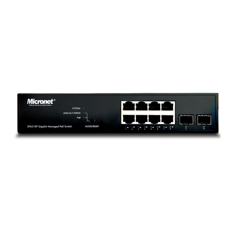
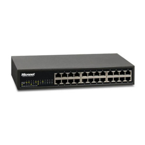
MicroNet SP6528 User manual

MicroNet

MicroNet SP6528 User manual

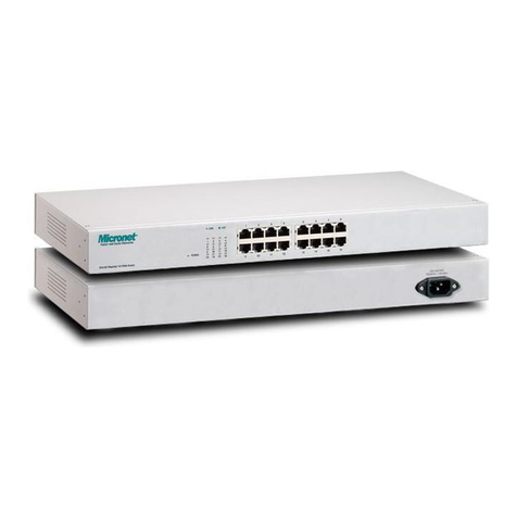
MicroNet SP698A User manual

MicroNet

MicroNet SP698A User manual

MicroNet SP659A User manual

MicroNet

MicroNet SP659A User manual

MicroNet SP6108WS User manual

MicroNet

MicroNet SP6108WS User manual

MicroNet SP1659P User manual

MicroNet

MicroNet SP1659P User manual

MicroNet SP684C User manual

MicroNet

MicroNet SP684C User manual

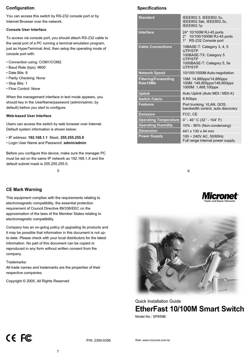
MicroNet SP659B User manual

MicroNet

MicroNet SP659B User manual

MicroNet SP212E User manual

MicroNet

MicroNet SP212E User manual

MicroNet SP1684B User manual

MicroNet

MicroNet SP1684B User manual

MicroNet SP616R User manual

MicroNet

MicroNet SP616R User manual

MicroNet SP6008P User manual

MicroNet

MicroNet SP6008P User manual

MicroNet SP616DB User manual

MicroNet

MicroNet SP616DB User manual

MicroNet SP1200A User manual

MicroNet

MicroNet SP1200A User manual

MicroNet SP6008PWS User manual

MicroNet

MicroNet SP6008PWS User manual

MicroNet SP659C User manual

MicroNet

MicroNet SP659C User manual

MicroNet SP508C User manual

MicroNet

MicroNet SP508C User manual

MicroNet SP6008P User manual

MicroNet

MicroNet SP6008P User manual

MicroNet SP6510P8 User manual

MicroNet

MicroNet SP6510P8 User manual

MicroNet SP6824P User manual

MicroNet

MicroNet SP6824P User manual

MicroNet SP676C User manual

MicroNet

MicroNet SP676C User manual

MicroNet SP6108I User manual

MicroNet

MicroNet SP6108I User manual

MicroNet SP6510P8 User manual

MicroNet

MicroNet SP6510P8 User manual

MicroNet SP212E User manual

MicroNet

MicroNet SP212E User manual

MicroNet SP218D User manual

MicroNet

MicroNet SP218D User manual

Popular Switch manuals by other brands

Extron electronics FOX T USW 203 installation guide

Extron electronics

Extron electronics FOX T USW 203 installation guide

D-Link DSH-8 - 10/100Mbps Dual Speed SOHO Hub user guide

D-Link

D-Link DSH-8 - 10/100Mbps Dual Speed SOHO Hub user guide

Applied Wireless SF900C user guide

Applied Wireless

Applied Wireless SF900C user guide

SMC Networks SMC8024L2 Technical specifications

SMC Networks

SMC Networks SMC8024L2 Technical specifications

ATEN UC2322 user manual

ATEN

ATEN UC2322 user manual

Genie IP24GESP2 user manual

Genie

Genie IP24GESP2 user manual

Siemens CNFS Series operating instructions

Siemens

Siemens CNFS Series operating instructions

StarTech.com 8STIES5102 manual

StarTech.com

StarTech.com 8STIES5102 manual

Servodan Minilux 41-055 Fitting and operating instructions

Servodan

Servodan Minilux 41-055 Fitting and operating instructions

LEGRAND AlphaRex3 DY21 GPS/DCF manual

LEGRAND

LEGRAND AlphaRex3 DY21 GPS/DCF manual

Patton electronics 360 user manual

Patton electronics

Patton electronics 360 user manual

GRASS VALLEY TRITON installation manual

GRASS VALLEY

GRASS VALLEY TRITON installation manual

D-Link Web Smart Switch DGS-1210-16 product manual

D-Link

D-Link Web Smart Switch DGS-1210-16 product manual

Indy 32884 Installation and use

Indy

Indy 32884 Installation and use

SMC Networks ISE20B Operation manual

SMC Networks

SMC Networks ISE20B Operation manual

Maxtrack CH 11 L user manual

Maxtrack

Maxtrack CH 11 L user manual

H3C S5500-EI series installation guide

H3C

H3C S5500-EI series installation guide

ORiNG IGPS-1082GP Series Quick installation guide

ORiNG

ORiNG IGPS-1082GP Series Quick installation guide

manuals.online logo
manuals.online logoBrands
  • About & Mission
  • Contact us
  • Privacy Policy
  • Terms and Conditions

Copyright 2025 Manuals.Online. All Rights Reserved.