Introduction
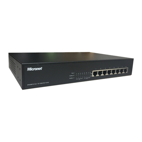
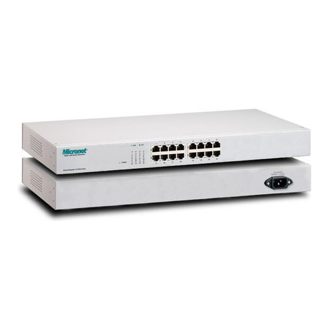
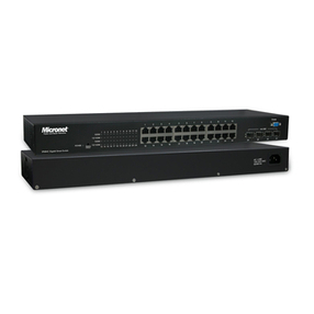
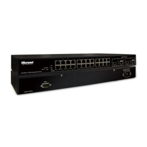
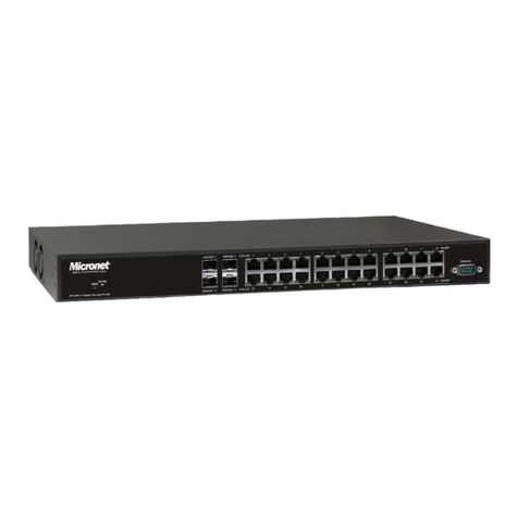
Micronet SP6528 Gigabit Managed Switch is a Layer 2+ managed
switch with 24 x 10/100/1000Mbps ports and 4 x 1G SFP uplink ports.
With 56 Gbps switching performance across all 28 ports, it provides
very prompt response time for applications and transmission speed
while transferring heavy load of data.
Micronet SP6528 is a very easy to install and user-friendly Gigabit
Managed Switch for your infrastructure application. By offering very rich
management features, it allows quick deployment, infrastructure
expansion with functionality, security, and manageability for different
network infrastructure applications. Micronet SP6528 is a perfect and
cost effective solution for small and mid size businesses.
Package Contents
Before you start installing the device, verify the following items are in
the package:
‧SP6528 Gigabit Managed Switch
‧Manual CD
‧Mounting accessory
‧Power cord
‧Quick Installation Guide
4
3
1 2
Key Features
‧Support automatic Voice VLAN for quick deployment of
VoIP, and IP-based surveilliance system
‧Support Link Aggregation (IEEE 802.3ad) to increase
bandwidth by automatically aggregate several links together
‧Support QoS (Port-based/IEEE 802.1p) feature to
preserve network bandwidth and allow maximum control of
network resources
‧Support IGMP Snooping and immediate leave features
to prevent flooding of IP multicast traffic and limit bandwidth-
intensive of video traffic
‧Support STP ,Reserve STP (RSTP) and MSTP features
to ensure faster recovery from failed links and enhance
overall network reliability
‧Allow Telnet, and IPv6 Web interface (both HTTP and
HTTPS) access
‧Support Access Control Lists (ACLs) restrict access to
sensitive network resources by denying packets based on
source and destination MAC addresses, IP addresses, and
TCP/UDP ports
‧Support IEEE 802.1Q VLAN-segmented broadcast
domains reduce broadcast traffic and increase LAN security
and performance
‧Support 802.3az Green-Ethernet to save power usage
when network traffic is low
‧Support console port for multiple management access
through CLI/SNMP/Web/Telnet
‧Support Secure Shell (SSH) & Secure Sockets Layer
(SSL/HTTPS) encrypts Telnet and web access to the switch
for secure network management
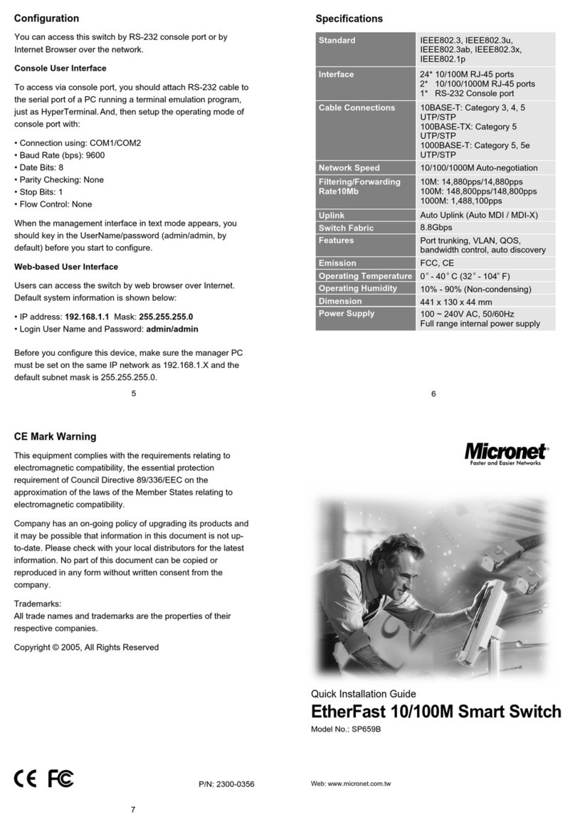
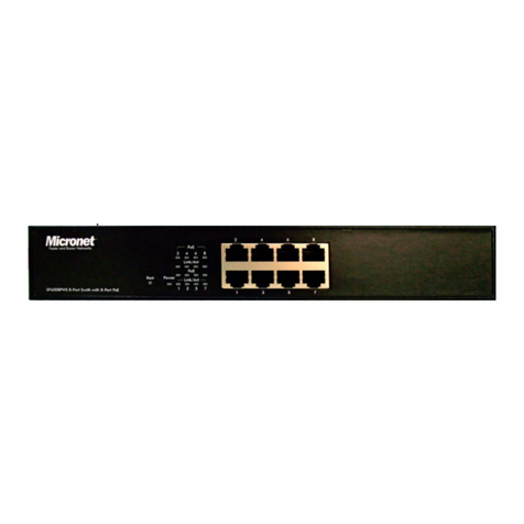
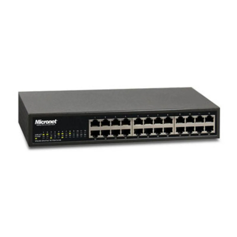
Physical Description
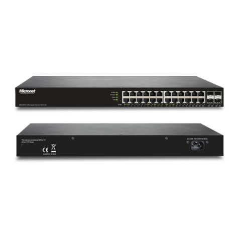
Front Panel
Rear View
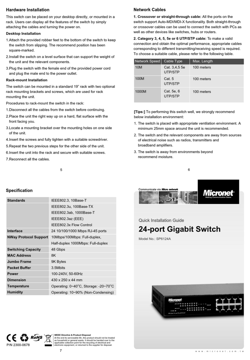
Hardware Installation
‧Connecting to an Ethernet Port for Switch Web Management
1.Connect one end of an RJ-45 cable to the Ethernet port on the
front panel and the other end to a PC or terminal for web interface
management.
2.Connect one end of an RJ-45 cable to the Ethernet port on the
front panel and the other end to network devices such as IP
cameras, IP phones etc. Make sure the switch port's Link LED
lights up.
‧Cabling Requirements for 1000Base-SX/LX SFP Module
The SP6526 supports more complex and comprehensive cabling
using fiber media. There are two categories of fiber, multimode
and single mode. The latter is categorized into several classes by
the supported distance; they are SX, LX, LHX, XD, and ZX. From
the viewpoint of connector type, there are LC and Bi-Di LC.
Gigabit Fiber with multimode LC SFP module
‧Gigabit Fiber with single-mode LC SFP module
‧Gigabit Fiber with Bi-Di LC 1310nm SFP module
‧Gigabit Fiber with Bi-Di LC 1550nm SFP module
For more details, please refer to the user manual.
1.
1.
1.
1.
1.
‧
‧
‧
‧
‧
‧
‧
‧
‧
‧
POWER
LINK/ACT
10/100M
LINK/ACT
1000M
DIAG
Green
Amber
Green
Green
Amber
Off
Shows the system is powered up.
The LED lights up to Indicate a valid
connection on the port. Otherwise, the
LED is off to indicate no link on the port.
When the LED blinks, it indicates the port
is active and transmitting data.
LED lights up, it indicates a successful
connection of that port is established.
Otherwise, it indicates the link is off or
no-link detected of that port.
When the LED blinks, it indicates the port
is activating and transmitting data.
The system diagnostic test has completed
sucessful
System diagnostic in progress
System boot up failed
