4
1 2
Introduction
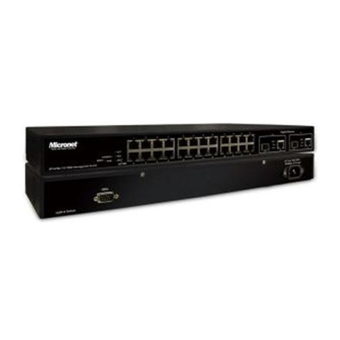
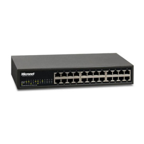
Micronet SP659B is a 24 ports 10/100M plus 2 ports Gigabit
smart switch. It provides powerful, high-performance Ethernet
Smart Switch, with 2 ports capable of 10, 100 and 1000Mbps
for allowing you to keep up with expending network needs. The
switch is plug-n-play and also fully compliant with all kinds of
network protocols.
Compared with ordinary dumb switches, the 24+2G ports Smart
Switch embeds advanced management capability, like port
trunk, VLAN and QoS and can be managed through console
port or web-based UI. Moreover, it also supports auto-discovery
function, auto-negotiation for speed and duplex mode.
Features
3
•
•
•
•
•
•
•
•
•
•
•
•
Compliant with IEEE802.3 10Base-T, IEEE802.3u 100Base-
TX, IEEE802.3ab 1000Base-T, IEEE802.3x flow control and
IEEE802.1p traffic prioritization standards
Support auto-negotiation function to automatically select
optimal speed (10/100/1000M) and mode (Full/Half Duplex)
Support 802.3x flow control for full-duplex mode and back-
pressure flow control for half-duplex mode
Support 26 groups of port-based VLAN
Support 7 groups of port trunk and up to 4 ports per trunk
Support Port-based, tag-based and TOS to achieve QoS
priority.
Support per-port bandwidth control
Provide local console port or web-based interface for
configuration
Provide auto-discovery function for easy network
management
Support auto uplink, no more cross-over cable
Forward and filter packets at non-blocking, full wire speed
100 - 240V AC, full range internal power supply
•
•
•
•
•
•
•
Installation
Hardware installation
The switch can be mounted in an EIA standard 19-inch rack,
which can be placed in a wiring closet with other equipment.
Attach the mounting brackets at the switch's front panel (one on
each side), and secure them with the provided screws. Then,
use screws provided with the equipment rack to mount each
switch in the rack.
Connecting your network
The switch provides 24 RJ-45 ports of 10/100M and 2 RJ-45
ports of 10/100/1000M. Just connect one end of the cable to
the switch and the other end to a desired device. Once the
connections between two end devices are made successfully,
turn on the power and the switch is operational.
Note: To prevent costly equipment damage and downtime,
please consider installing a surge suppression device or a UPS
(Un-interrupted Power Supply).
For cable selection, refer to the following table
Cat. 3, 4, 5 UTP/STP 100 meters
Network Speed Cable Type Max. Length
10M
100M
1000M
Cat. 5 UTP/STP
Cat. 5, 5e UTP/STP
100 meters
100 meters
Physical Description
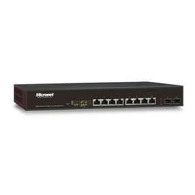
SP659B front view
Please refer to the following table for LED definition
Power
On
Off Power is off
Power is on
LED Status Operation
LINK/ACT
On Green Connection established
Blink/Green Transmitting or receiving data
Off No link.
10/100M (1-24 port)
1000M On/Green
On/Green 100M connection established
1000M connection established
LED Status Operation
On/Green 10M connection established
Blink/Green Transmitting or receiving data
100M
ACT
10M
10/100/1000M (25, 26 port)
POWER
LINK/ACT
123456
1 2 3 4
5 6 7 89 10 11 12
13 14 15 16 17 18 19 20 21 22 23 24
1000M
100M
10M
ACT
1000M
100M
10M
ACT
25 LINK 26 LINK
LINK ACT
78910 11 12
13 14 15 16 17 18
19 20 21 22 23 24
SP659B EtherFast 10/100M Smart Switch
CONSOLE
9600, 8, N, 1
Before you start installing the device, verify the following items
are in the package:
EtherFast 10/100M Smart Switch
Quick installation guide
Manual CD
RS-232 cable
Rack-mount brackets
Rubber foot and screws
Power cord
•
•
•
•
•
•
•
Package Contents
