Q I G Quick Installation Guide
PRINTED ON RECYCLED PAPER
Quick Installation Guide
Po we r
Redunda nt I nput powe r
Power con su mption( Typ. ) 11 Watt s
Ov erload cu rrent pro te ction Pr esent
Ph ys ic al C haracteristic
En closure I P- 30
Di mension ( W x D x H) 54 .3(W)x1 08 .5(D)x1 45.1(H) m m (2.13x4 .2 7x5.71 in ch.)
Sw itch Prop erties
Sw itch late ncy: less t ha n 7us
Sw itch band width: 20 Gb ps
Weigh t (g) 88 9 g
Ju mbo fra me Up t o 9.6K Byte s
Fa ul t Co nt act
Relay Relay outp ut to carry c apacity o f 1A at 24VDC
Reverse Polari ty Protec tion
Pr esent
Q I G
For pin assignments for different types of cables, please refer to the following
tables.
Configurations
After installing the switch, the green power LED should turn on. Please refer to the
following tablet for LED indication.
Specifications
OR in g Sw it ch Model
Ph ys ic al P orts
Te ch no lo gy
Et hernet St an dards
IE EE 802.3 fo r 10 Base-T
IE EE 802.3u f or 1 00Base-T X and 100Ba se-FX
IE EE 802.3a b fo r 1000Bas e-T
IE EE 802.z fo r 10 00Base-X
IE EE 802.3x f or F low contr ol
IE EE 802.3a f/ at PoE sp ecifica tion
10 /100/10 00 Base-T(X ) with
P.S. E. Po rt s in RJ45 Aut o
MD I/MDIX
MA C Tabl e 8K
Packet bu ffer 4M bit
Pr ocessin g St ore-a nd -Fo rward
8 (P .S .E . wi th IEEE 802.3at)
IG PS -1 08 2GP
Du al DC input s. 5 0-57VDC o n 6-pin ter minal blo ck
10 0/1000B as e-X w ith SFP por t 2
10/100 Base-T(X) MDI/MDI-X
Pin Number MDI port MDI-X port
1 TD+(transmit) RD+(receive)
2 TD-(transmit) RD-(receive)
3 RD+(receive) TD+(transmit)
4 Not used Not used
5 Not used Not used
6 RD-(receive) TD-(transmit)
7 Not used Not used
8 Not used Not used
Note: “+” and “-” signs represent the polarity of the wires that make up each
wire pair.
Wiring
The switch supports dual redundant power supplies, Power Supply1
(PWR1) and Power Supply 2 (PWR2). The connections for PWR1,
PWR2 and the RELAY are located on the terminal block.
STEP 1: Insert the negative/positive wires into the V-/V+ terminals,
respectively.
STEP 2: To keep the DC wires from pulling loose, use a small flat-
blade screwdriver to tighten the wire-clamp screws on the front of the
terminal block connector.
PWR-1PWR-2
1A@24V
V2- V2+ V1- V1+
Fault
Power inputs
The two sets of relay contacts of the 6-pin terminal block connector are used to detect user-
configured events. The two wires attached to the fault contacts form an close circuit when a
user-configured event is triggered. If a user-configured event does not occur, the fault
circuit remains opened.
Relay contact
1000Base-T MDI/MDI-X
Pin Number MDI port MDI-X port
1 BI_DA+ BI_DB+
2 BI_DA- BI_DB-
3 BI_DB+ BI_DA+
4 BI_DC+ BI_DD+
5 BI_DC- BI_DD-
6 BI_DB- BI_DA-
7 BI_DD+ BI_DC+
8 BI_DD- BI_DC-
Grounding and wire routing help limit the effects of noise due to electromagnetic
interference (EMI). Run the ground connection from the ground screws to the grounding
surface prior to connecting devices.
Grounding
Cable Types and Specifications:
Cable Type Max. Length Connector
10BASE-T Cat. 3, 4, 5 100-ohm UTP 100 m (328 ft) RJ-45
100BASE-TX Cat. 5 100-ohm UTP UTP 100 m (328 ft) RJ-45
1000BASE-T Cat. 5 / Cat. 5e 100-ohm UTP UTP 100 m (328 ft) RJ-45
Version 1.0
Weigh t (g) 71 0 g 74 0 g72 2 g 73 5 g 73 5 g 74 0 g
En vi ro nm ental
-4 0 to 85 C (-40 to 18 5 F )
o o
St orage Tem perat ur e
-4 0 to 75 C (-40 to 16 7 F )
o o
Op erating Tempe rature
5% t o 95% Non-c on densingOp erating H umidity
Re gu la to ry Approvals
EN 5 5032, CIS PR 32, EN 6100 0-3-2, EN 6 1000-3- 3, F CC Pa rt 1 5 B class AEM I
EN 5 5024 (IEC /E N 61000-4 -2 (ESD), I EC/EN 610 00 -4-3 (RS) ,IEC/EN 6 10 00-4- 4 (E FT ), IEC/EN 6 1000-4- 5 (Surge) ,
IE C/EN 6100 0- 4-6 (CS), I EC/EN 610 00-4-8( PF MF), IEC/ EN 61000- 4- 11 (DIP))
EM S
IE C60068- 2- 27Sh ock
IE C60068- 2- 31
IE C60068- 2- 6Vi brati on
EN 60950-1 c om pliant
Sa fety
Fr ee Fa ll
Wa rr an ty
5 ye ars
MT BF ( hr s)
58 1633 hrs
DI P Sw it ch
DI P-Swi tc h 1
DI P-Swi tc h 2 Power-1 f ailed war ning : (ON) e nable, (O FF ) disab le
DI P-Swi tc h 3 DIP switc h 3 an d 4 (ON) : SFP sp eed setti ng to 100Mb ps
LE D In di ca tors
Power Ind ic ator (PWR ) Gr een : Pow er L ED x 3
DI P-Swi tc h 4
DI P switch 3 an d 4 (O FF) : SFP spe ed settin g to 1000Mb ps (defa ul t)
Power-2 f ailed war ning : (ON) e nable, (O FF ) disab le
Fault I ndicato r (Fa ul t) Am ber : Indic at e power fai led eve n warning
10 /100/10 00 Base-T(X ) RJ45
Port Indi ca tor
Gr een for por t Li nk/Act.
Gr een for PoE e nable i nd icator.
10 0/1000B as e-X S FP Port
In dicator G re en for port L ink/Act .
CE E MC (EN 5502 4, E N 55032), F CC Part 1 5 BEM C
ORing Industrial Networking Corp.
Copyright© 2017 ORing
All rights reserved.
TEL: +886-2-2218-1066
FAX: +886-2-2218-1014
Website: www.oringnet.com
E-mail: support@oringnet.com
10/100Base-T(X) P.S.E. RJ-45 Port
Pin No.
TD+ with PoE Power input +
# 1
Assignments
# 2
# 3
# 6
TD- with PoE Power input +
RD+ with PoE Power input -
RD- with PoE Power input -
1000Base-T P.S.E. RJ-45 Port
Pin No.
BI_DA+ with PoE Power input +
# 1
Assignments
# 2
# 3
# 4
BI_DA- with PoE Power input +
BI_DB+ with PoE Power input -
BI_DC+
BI_DC-
# 5
# 6
# 7
# 8
BI_DB- with PoE Power input -
BI_DD+
BI_DD-
DC power module 1 activated
DC power module 2 activated
IG PS -1 08 2GP-24V
PoE Pow er budget 18 0 Wat ts
11 Watt s
Du al DC input s. 1 2-57VDC o n 6-pin ter minal blo ck
60 W at 12~24V DC , 120W at 2 4~ 57VDC
91 6 g
53 7330 hrs
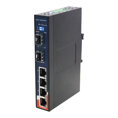
IGPS-1082GP Series
IGPS-1082GP Series
G I G A B I T
I N D U S T R I A L
S W I T C H
P o E
Industrial Unmanaged Gigabit PoE Switch
