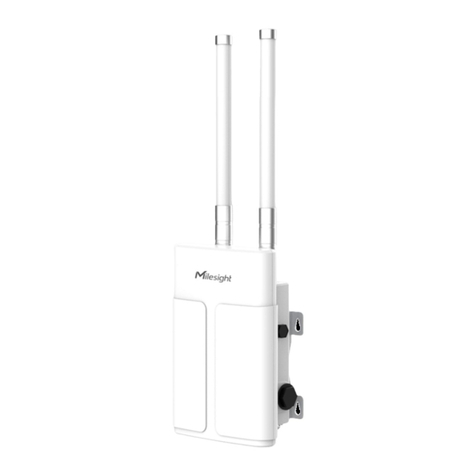
Milesight UG65 User manual

1
Milesight & AWS IoT Core for LoRaWAN

2
Table of Contents
1
Document Information
.................................................................................................................... 3
2
Overview
............................................................................................................................................ 3
3
Hardware Description
...................................................................................................................... 3
4
Setup AWS
......................................................................................................................................... 4
5
Set up the Gateway
.......................................................................................................................... 5
6
Add End Device(s)
............................................................................................................................ 8
7
Verifying Operation –a “Hello World” example
........................................................................... 8
8
Debugging
....................................................................................................................................... 12

3
1Document Information
1.1 Naming Conventions
The term “downlink device” or “endpoint device” is used in this document to refer
to a LoRaWAN device that connects to a LoRaWAN “Gateway”. The “Gateway” in
turn, connects to AWS IoT Core for LoRaWAN.
1.2 Revision History (Version, Date, Description of change)
Version
Date
Description
1.0
2021-01-05
Initial test along original guide
2Overview
UG65/UG67 is a robust 8-channel indoor LoRaWAN® gateway. In the LoRaWAN®
Gateway series from Milesight IoT, UG65/UG67 both adopt SX1302 as the LoRa
module, and high-performance quad-core CPU. UG65/UG67 supports connection
with more than 2000 nodes. UG65 has line of sight up to 15km and can cover
about 2km in urbanized environment, which is ideally suited to smart office, smart
building and many other indoor applications.
3Hardware Description
3.1 Data Sheet
Link:
https://resource.milesight-iot.com/milesight/document/ug65-datasheet-en.pdf
3.2 Standard Kit Contents
Package contents:
1 × UG65;
1 × Ethernet Cable;
1 × DC Jack Power Adapter;
1 × Mounting Bracket;
2 × Bracket Fixing Screws;
4 × Wall Mounting Kits;
1 × Warranty Card;
1 × Quick Start Guide;
Link to its official website for more detail:
https://www.milesight-iot.com/lorawan/gateway/ug65/
3.3 User Provided items
1 × Computer

4
Internet accessible network environment
3.4 3rd Party purchasable items
1 × Ethernet Cable;
1 × DC Jack Power Adapter;
1 × Mounting Bracket;
2 × Bracket Fixing Screws;
4 × Wall Mounting Kits;
3.5 Additional Hardware References
Link to its official website for more detail:
https://www.milesight-iot.com/lorawan/gateway/ug65/
4Setup AWS
If you don’t have an AWS account, refer to the instructions in the guide here. The
relevant sections are Sign up for an AWS account and Create a user and grant
permissions.
4.1 Overview
The high-level steps to get started with AWS IoT Core for LoRaWAN are as follows:
1. Onboard your Gateway (see section Add the Gateway to AWS IoT)
2. Onboard your Device(s) (see section Add a LoRaWAN Device to AWS IoT)
a. Verify device and service profiles
b. Set up a Destination to which device traffic will be routed and processed by a rule.
These steps are detailed below. For additional details, refer to the AWS LoRaWAN developer guide.
4.2 Add the Gateway to AWS IoT
4.2.1 Preparation
Refer to the online guide for steps required prior to onboarding your gateway.
4.2.2 Frequency Band selection and Role setup
Refer to the online guide for information on selecting an appropriate frequency band.
Follow the instructions in the section Add an IAM role to allow the Configuration and Update Server
(CUPS) to manage gateway credentials in the online guide.
4.2.3 Add the LoRaWAN Gateway
To register the Gateway with AWS IoT Core for LoRaWAN, follow the steps in this online guide under the
section Add a gateway using the console.
4.3 Add a LoRaWAN Device to AWS IoT
4.3.1 Preparation
Refer to the instructions in the section Before onboarding your wireless device in the online guide.
Then follow the instructions in the section Add your wireless device to AWS IoT Core for LoRaWAN here.
4.3.2 Verify Profiles

5
AWS IoT Core for LoRaWAN supports device profiles and service profiles. Device profiles contain the
communication and protocol parameter values the device needs to communicate with the network
server. Service profiles describe the communication parameters the device needs to communicate with
the application server.
Some pre-defined profiles are available for device and service profiles. Before proceeding, verify that
these profile settings match the devices you will be setting up to work with AWS IoT Core for LoRaWAN.
For more details, refer to the section Add profiles to AWS IoT Core for LoRaWAN in the online guide.
Proceed only if you have a device and service profile that will work for you.
4.3.3 Set up a Destination for device traffic
Because most LoRaWAN devices don't send data to AWS IoT Core for LoRaWAN in a format that can be
consumed by AWS services, traffic must first be sent to a Destination. A Destination represents the AWS
IoT rule that processes a device's data for use by AWS services. This AWS IoT rule contains the SQL
statement that selects the device's data and the topic rule actions that send the result of the SQL
statement to the services that will use it.
For more information, refer to the online guide (sections titled Add a destination using the console and
Create an IAM role for your destinations). Also refer to Create rules to process LoRaWAN device
messages in the online guide.
5Set up the Gateway
5.1 Set up Gateway hardware
User guide link: https://resource.milesight-iot.com/milesight/document/ug65-
user-guide-en.pdf
Quick guide link: https://resource.milesight-iot.com/milesight/document/ug65-
quick-guide-en.pdf
A. Connect the Ethernet cable and power cable to corresponding interfaces.
B. Pass two cables through the waterproof silicone and slid into the grooves.
C. Screw the protective cover back to the device.
UG6x can also be powered by 802.3af standard PoE injector or other PoE devices.
If both connected, DC power is preferred.
LED
Indication
Status
Description
POWER
Power Status
Off
The power is switched off
On
The power is switched on

6
STATUS
System Status
Blue Light
Static: the system is running properly
Red Light
The system goes wrong
LoRa
LoRa Status
Off
Packet Forwarder mode is running off
Blue Light
Packet Forwarder mode is running well
Wi-Fi
Wi-Fi Status
Off
Wi-Fi is disabled
Blue Light
Wi-Fi is enabled
LTE
Cellular Status
Off
SIM card is registering or fails to register
(or there are no SIM cards inserted)
Blue Light
Blinking slowly: SIM card has been registered
and is ready for dial-up
Blinking rapidly: SIM card has been registered
and is dialing up now
Static: SIM card has been registered and dialed
up successfully
ETH
Ethernet
Port Status
Off
Disconnected
Blue Light
Static: Connected
This section explains how to connect the gateway to network via WAN
connection, Wi-Fi or cellular.
1.Configure the Ethernet Connection
•Go to Network →Interface →Port page to select the Connection Type and
configure Ethernet port information.
•Click Save & Apply for changes to take effect.
•Connect Ethernet port of gateway to devices like router or modem.
•Log in the web GUI via the newly assigned IP address and go to Status →
Network to check Ethernet port status.
2. Configure the Wi-Fi Connection
•Go to Network →Interface →WLAN and select Client mode.
•Click Scan to search for Wi-Fi access point. Select the available one and
click Join Network.
•Type the key of Wi-Fi.
•Go to Status →WLAN to check Wi-Fi status. If it shows Connected, it
means gateway connects to Wi-Fi successfully.
3. Configure the Cellular Connection
•Go to Network →Interface →Cellular →Cellular Setting page to enable
cellular settings.
•Choose relevant network type and fill in SIM card information like APN or
PIN code.
•Click Save and Apply for changes to take effect.
•Go to Status →Cellular page to view the status of the cellular connection.
If it shows Connected, it means the SIM has dialed up successfully. On the

7
other hand, you can check the status of LTE indicator. If it keeps on light
statically, it means SIM has dialed up successfully.
5.2 Set up Gateway Software
System starts up seconds after UG65 is powered.
1.Via Web Interface
•Log in web interface, and go to Maintenance > Backup and Restore.
•Click Reset under Restore Factory Defaults.
•You will be asked to confirm if you’d like to reset it to factory defaults, click
Reset button.
•Then the gateway will reboot and restore to factory settings immediately.
•Please wait till STATUS light statically and the login page pops up again,
which means the gateway has already been reset to factory defaults
successfully.
2.Via Hardware
•Locate the reset button on the gateway, and take corresponding actions
based on the status of SYS LED.
SYS LED
Action
Static Blue
Press and hold the reset button for more than 5
seconds.
Static Blue →
Rapidly Blinking
Release the button and wait.
Off →Static Blue
The gateway is now reset to factory defaults.
It is suggested that you contact Milesight technical support first before you
upgrade gateway firmware. Gateway firmware file suffix is “.bin”. After getting
firmware file, please refer to the following steps to complete the upgrade.
•Go to Maintenance > Upgrade.
•Click Browse and select the correct firmware file from the PC.
•Click Upgrade and the gateway will check if the firmware file is correct. If
it’s correct, the firmware will be imported to the gateway, and then the
gateway will start to upgrade.
Use a web browser like Chrome to access default IP 192.168.23.150.
Default credentials to log in is:
•Username: admin
•Password: password
•Go to Packet Forwarder > General.
•Disable Milesight which indicates the gateway network server.
•Click +to add a Basic Station type.

8
•Fill in the AWS endpoint URI and corresponding certificates.
5.3 Additional Software References
Official support forum: https://support.milesight-iot.com/hc/en-us
5.4 Configure the Gateway device
Current firmware version of UG65 is on Status > Overview, starting by 60.0.0.x for
standard firmware. Minimum recommended version is 60.0.0.25. If lower, see Set
up Gateway Software. To register the Gateway with AWS IoT Core for LoRaWAN,
follow these steps:
•Packet forwarder is enabled by default, and the destination is its internal
network server. Under Multi-Destinations, disable Milesight and enable a
Basic Station.
•Fill in CUPS URI with what was copied when adding a gateway on AWS IoT
for LoRaWAN.
•Browse and import the cups.trust file that was downloaded when adding
a gateway on AWS IoT for LoRaWAN.
•Browse and import the .crt certificate that was downloaded from Secure >
Certificates.
•Browse and import the .pem file that was downloaded when adding a
gateway on AWS IoT for LoRaWAN.
•Fill in LNS URI with what was copied when adding a gateway on AWS IoT
for LoRaWAN.
•Browse and import the lns.trust file that was downloaded when adding a
gateway on AWS IoT for LoRaWAN.
6Add End Device(s)
For more info on device working refer to the AM100 series user manual
https://resource.milesight-iot.com/milesight/document/am100-series-user-
guide-en.pdf
7Verifying Operation –a “Hello World” example
Once setup is completed, provisioned OTAA devices can join the network and
start to send messages. Messages from devices can then be received by AWS
IoT Core for LoRaWAN and forwarded to the IoT Rules Engine.
Instructions for a sample Hello World application are given below, assuming that
the device has joined and is capable of sending uplink traffic. The architecture for
this sample application is:

9
7.1 Create lambda function for destination rule
Create the lambda function to process device messages processed by the
destination rule.
•Go to the AWS Lambda console (console.aws.amazon.com/lambda).
•Click on Functions in the navigation pane
•Click on Create function
•Select Author from scratch. Under Basic information, enter the function
name “
am100decoder
” and choose
Runtime Node.js 12.x
. from the drop-
down under Runtime.
•Click on Create function.
•Navigate to this Link to Milesight IoT’s decoder repository
and copy the
code for the lambda function.
•Under Function code, paste the copied code into the editor under the
index.js tab.
•Once the code has been pasted, choose “Deploy” to deploy the lambda
code.
•Click on the Permissions tab of the lambda function
•Change the Lambda Role Policy permission
oUnder Execution role, click on the hyperlink under Role name
oOn the Permissions tab, find the policy name and click on it
oChoose Edit policy, and choose the JSON tab
oAppend the following to the Statement section of the policy to allow
publishing to AWS IoT.
,
{
"Effect": "Allow",
"Action": [
"iot:Publish"
],

10
"Resource": [
"*"
]
}
oChoose Review Policy, then Save changes
•Create a test event that will allow you to test the functionality of the
lambda function.
oIn the drop-down for
Select a test event
, choose Configure test
events
oEnter a name for the test event under Event name
oPaste the following sample payload in the area under Event name:
{
"WirelessDeviceId": "ab35b5ec-00b6-4c02-9bec-1e4efa4c7ba1",
"PayloadData": "A2cHAQRocgZlRABeAVAABWosAAd9ZgIIfQwACXN5Jw==",
"WirelessMetadata": {
"LoRaWAN": {
"DataRate": "2",
"DevEui": "24e124128a390388",
"FCnt": 65,
"FPort": 85,
"Frequency": "865500000",
"Gateways": [
{
"GatewayEui": "24e124fffef128ea",
"Rssi": -33,
"Snr": 10.5
}
],
"Timestamp": "2021-03-16T07:37:18Z"
}
}
}
•Choose Create to save the event
•Navigate to the AWS IoT console, choose Test on the navigation pane, and
select MQTT client.
•Configure the MQTT client to subscribe to “#” (all topics)

11
•Click on Test in the Lambda function page to generate the test event you
just created
•Verify the published data in the AWS IoT Core MQTT Test client
oOpen another window. Go to AWS IoT Console, select Test, under
Subscription Topic, enter # and select to Subscribe to topic
oThe output should look similar to this:
7.2 Create the Destination rule
In this step, you create the IoT rule that forwards the device payload to your
application. This rule is associated with the destination created earlier in Set up
a Destination for device traffic.
•Navigate to the AWS IoT console.
•In the navigation pane, choose Act. Then, choose Rules.
•On the Rules page, choose Create.
•On the Create a rule page, for Name, enter
LoRaWANRouting
. For
Description, enter a description of your choice. Note the name of your rule.
The information will be needed when you provision devices to run on AWS
IoT Core for LoRaWAN.
•Leave the default Rule query statement: ‘SELECT * FROM 'iot/topic'
unchanged. This query has no effect at this time, as traffic is currently
forwarded to the rules engine based on the destination.

12
•Under Set one or more actions choose Add action.
•On the Select an action page, choose Republish a message to an AWS IoT
topic. Scroll down and choose Configure action.
•On the Configure action page, for Topic, enter
project/sensor/decoded
.
The AWS IoT Rules Engine will forward messages to this topic.
•Under Choose or create a role to grant AWS IoT access to perform this
action, choose Create Role.
•For Name, enter a name of your choice.
•Choose Create role to complete the role creation. You will see a “Policy
Attached” tag next to the role name, indicating that the Rules Engine has
been given permission to execute the action.
•Choose Add action.
•Add one more action to invoke the Lambda function. Under Set one or
more actions choose Add action.
•Choose Send a message to a Lambda function
•Choose Configure action
•Select the
am100decoder
lambda function created earlier and choose Add
action
•Then, choose Create rule.
•A “Success” message will be displayed at the top of the panel, and the
destination has a rule bound to it.
You can now check that the decoded data is received and republished by AWS
by triggering a condition or event on the device itself.
1. Go to the AWS IoT console. In the navigation pane, select Test,
and choose MQTT client.
2. Subscribe to the wildcard topic ‘#” to receive messages from all
topics
3. You should see traffic similar to that shown below.
8Debugging
Official support: https://support.milesight-iot.com/hc/en-us
Use a web browser like Chrome to access default IP 192.168.23.150, or your
custom one.
Default credentials to log in is:
Other manuals for UG65
4
This manual suits for next models
1
Table of contents
Other Milesight Gateway manuals
Milesight
Milesight UG63 User manual
Milesight
Milesight UG63 User manual
Milesight
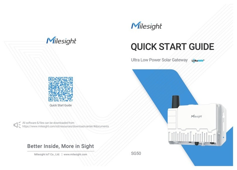
Milesight SG50 User manual
Milesight
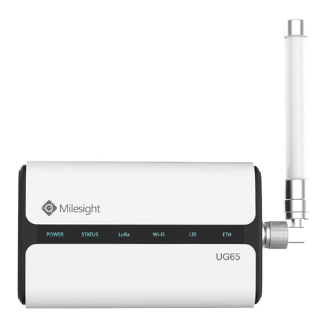
Milesight UG65 User manual
Milesight
Milesight UG63-868M User manual

Milesight
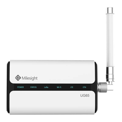
Milesight UG65 User manual
Milesight
Milesight LoRaWAN UG6 Series User manual
Milesight
Milesight UG67 User manual
Milesight
Milesight Urbana GI03 User manual

Milesight
Milesight SG50 User manual


