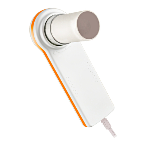
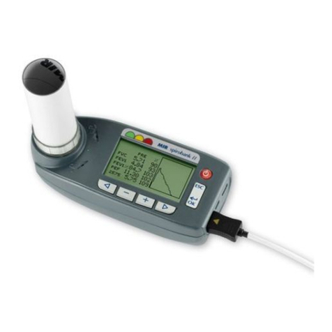
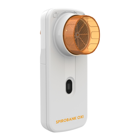
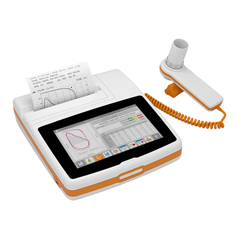
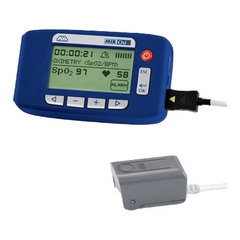
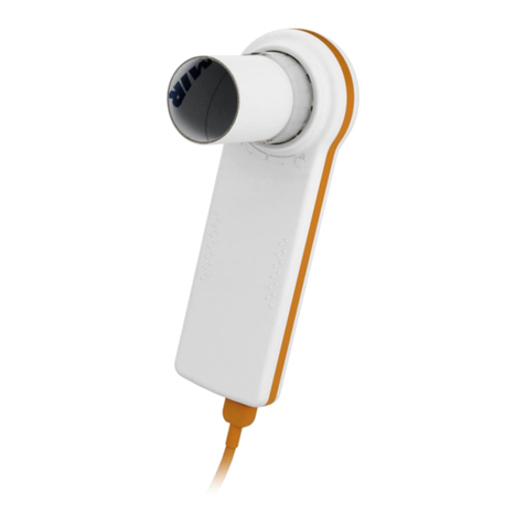
MIR MiniSpir Light User manual

MiniSpir
Page 1 of 27
Rev.1.4
Service Guide
Service manual Rev. 1.0
Date issued 20.08.2014
Date of approval 20.08.2014

MiniSpir
Page 2 of 27
Rev.1.4
Service Guide
INDEX
1. INTRODUCTION..................................................................................................................................................................................................................3
1.1. INTRODUCTORY REMARKS .............................................................................................................................................................................................3
1.1.1. General Aspects..................................................................................................................................................................................................................3
1.1.2. Safety Aspects.....................................................................................................................................................................................................................3
1.1.3. Legal Aspects .....................................................................................................................................................................................................................3
1.1.4. Environmental Aspects...................................................................................................................................................................................................... 3
1.2. DATA REGISTRATION........................................................................................................................................................................................................3
1.2.1. Equipment and customer registration / Service file ........................................................................................................................................................4
1.2.2. Configuration register........................................................................................................................................................................................................4
1.2.3. Product documentation .....................................................................................................................................................................................................4
1.2.4. Technical modifications ....................................................................................................................................................................................................4
1.2.5. Product evaluation .............................................................................................................................................................................................................4
1.2.6. Additional Information ......................................................................................................................................................................................................4
1.3. GENERAL...............................................................................................................................................................................................................................5
1.3.1. Technical Data...................................................................................................................................................................................................................5
1.3.1.1. MiniSpir unit ......................................................................................................................................................................................................................5
1.4. STANDARDS APPLIED ........................................................................................................................................................................................................5
2. HARDWARE DESCRIPTION ..............................................................................................................................................................................................6
2.1. MAIN BOARD MODULE .....................................................................................................................................................................................................6
2.1.1. Room temperature sensor..................................................................................................................................................................................................6
2.1.2. USB communication port..................................................................................................................................................................................................7
2.1.3. Oximetry port .....................................................................................................................................................................................................................7
2.2. TURBINE FLOWMETER.....................................................................................................................................................................................................7
3. MAINTENANCE ...................................................................................................................................................................................................................8
3.1. GENERAL...............................................................................................................................................................................................................................8
3.2. TEST EQUIPMENT ..............................................................................................................................................................................................................8
3.3. CHECKLIST............................................................................................................................................................................................................................8
3.3.1. Functional test....................................................................................................................................................................................................................9
3.3.1.1. Software version .................................................................................................................................................................................................................9
4. REPLACEMENT PROCEDURES .......................................................................................................................................................................................9
4.1. General .....................................................................................................................................................................................................................................9
4.2. Cover....................................................................................................................................................................................................................................... 10
4.2.1. Opening the device .......................................................................................................................................................................................................... 10
4.3. PCBs and components .......................................................................................................................................................................................................... 10
4.3.1. Replacing the USB cable in case of MiniSpir Light....................................................................................................................................................... 10
4.3.2. Turbine..............................................................................................................................................................................................................................11
4.3.2.1. Cleaning the reusable turbine...........................................................................................................................................................................................11
4.3.2.2. Calibration of the reusable turbine.................................................................................................................................................................................. 12
4.3.3. Internal software upgrade procedure .............................................................................................................................................................................. 12
4.4. Oximeter module ................................................................................................................................................................................................................... 13
4.4.1. Replacing of the oximetry module .................................................................................................................................................................................. 14
4.5. Testing procedures ................................................................................................................................................................................................................ 14
4.5.1. Testing procedures .......................................................................................................................................................................................................... 14
5. SPARE PARTS....................................................................................................................................................................................................................... 17
5.1. ORDERING .......................................................................................................................................................................................................................... 17
5.2. DELIVERY............................................................................................................................................................................................................................ 17
5.2.1. Ordering PCB's................................................................................................................................................................................................................ 17
5.2.2. Warranty claims................................................................................................................................................................................................................ 17
5.3. RETURN SHIPMENTS ...................................................................................................................................................................................................... 18
6. TROUBLESHOOTING....................................................................................................................................................................................................... 18
6.1. The device does not switch on .............................................................................................................................................................................................. 18
6.2. The device does not measure spirometry at all .................................................................................................................................................................... 18
6.3. The device does not measure spirometry correctly.............................................................................................................................................................. 18
6.4. The device does not measure oximetry at all ....................................................................................................................................................................... 19
6.5. The device does not measure oximetry correctly ................................................................................................................................................................. 19
6.6. The data communication via USB does not function .......................................................................................................................................................... 19
6.7. Index of components ............................................................................................................................................................................................................. 19
APPENDIX A: SPARE PARTS LIST .............................................................................................................................................................................................. 20
APPENDIX B: SERVICE INFO'S (Product Change Notes) ........................................................................................................................................................ 24
APPENDIX C.................................................................................................................................................................................................................................... 25
ANNEX.............................................................................................................................................................................................................................................. 27

MiniSpir
Page 3 of 27
Rev.1.4
Service Guide
1. INTRODUCTION
1.1. INTRODUCTORY REMARKS
1.1.1. General Aspects
The spirometers from the product group MIR052-MIR053 are marketed under the label MiniSpir.
This manual has been written for technicians involved in the service of the MiniSpir. Service can be carried out by the
service organization of the manufacturer or by any other technician authorized by MIR srl.
The manufacturer will not be held responsible for the results of maintenance or repairs by unauthorized persons.
1.1.2. Safety Aspects
Safe execution of the procedures in this manual requires technical experience and general knowledge of safety precautions.
Before you start any operation on the unit, you must have first read both the User and this Service
Manual.
Warnings, Cautions and Notes are used throughout this manual to bring special matters to the immediate attention of the
reader.
Warning The Warning concerns danger to the safety of the technician or user.
Caution The Caution draws attention to an action which may damage the equipment.
Note The Note points out a statement deserving more emphasis than the general text, but which does not
deserve a Warning or Caution.
Warning
In order to prevent unforeseen incidents, keep away from sensitive electronical devices. Inside the MiniSpir there
are low voltages and very low currents, so these represent no danger for persons with experience and with a
general knowledge of safety precautions.
The sequence of steps in a procedure may also be important from the point of view of personal safety and prevention of
damage, therefore never change the sequence of steps or alter any procedure.
1.1.3. Legal Aspects
This manual and the information herein are property of MIR srl (Rome, Italy).
Copying this manual in whole or in part is strictly forbidden.
MIR srl disclaims any responsibility for personal injury and/or damage to equipment caused by:
negligence or disregard of a Warning or Caution
deviation from any of the prescribed procedures
execution of activities which are not prescribed
ignorance of the general safety precautions for handling tools and the use of electricity
incorrect or unreasonable use
1.1.4. Environmental Aspects
Please dispose properly of any items replaced, following all the local regulations.
All components (housing, PCBs, electronic and disposable parts, etc.) must be disposed of according to the relevant local
regulations.
1.2. DATA REGISTRATION

MiniSpir
Page 4 of 27
Rev.1.4
Service Guide
1.2.1. Equipment and customer registration / Service file
From the point of view of safety and product liability the following data must be registered for each unit:
Equipment data
Model, REF code and serial number
Customer data
date of purchase
name and full address of the customer
Service data
log of all service activities
Configuration data
the actual configuration of the equipment (hardware and software versions)
The distributor (through their dealer and/or service organization, if any) is responsible for maintaining these records and
they must be able to provide these data when requested.
1.2.2. Configuration register
A configuration file gives the serial numbers and/or batch numbers of main sub-assemblies and/or important parts of
each unit. The parts listed in a configuration file are defined as registered parts. For example parts as mainboards, display
and internal software.
Note
MIR srl has the original configuration file of each unit sold. Any possible changes in the original configuration of
the supplied units must be filed and the distributor must be able to provide this data.
1.2.3. Product documentation
The documentation set for the MiniSpir includes a User Manual. The User Manual is a recommended item for all service
engineers. The user manual is available in the following languages:
English
Spanish
German
French
Italian
Portuguese
1.2.4. Technical modifications
This publication could include technical inaccuracies or typographical errors. Changes are periodically made to the
information herein; these changes will be published as Service Info in appendix B of this Service Manual.
Note
Some functions described in this manual may not be activated in the present software or hardware version. For
detailed information, please refer to the User Manual.
1.2.5. Product evaluation
In order continuously to improve the quality of our products, MIR srl requests that the service organizations should report
any device issue which may be discovered. When the same issue regularly occurs or when a safety issue occurs, MIR srl
would like you to send us a product complaint report. The report must contain the name, the type of product, a detailed
description of the problem, the frequency of the same problems, the quantity of sold equipment and your solution to the
problem (if any).
1.2.6. Additional Information
Please do not hesitate to contact MIR if you require additional information.

MiniSpir
Page 5 of 27
Rev.1.4
Service Guide
Manufacturer’s address:
MIR srl
Medical International Research
Via del Maggiolino, 125
00155 Rome
Italy
Tel.: +39/06/2275 4777
Fax.: +39/06/2275 4785
Email: [email protected]
1.3. GENERAL
MiniSpir is an “open circuit system” for the measurement of inspiratory and expiratory lung function parameters and
oximetry values, such as pulse rate and SpO2. It is suitable for basic lung function analysis of the mechanical respiratory
tract parameters. Three different respiratory tests can be performed:
the forced vital capacity test (FVC),
the slow Vital Capacity test (VC/IVC)
the Maximum Voluntary Ventilation test (MVV)
MiniSpir has been designed and manufactured to ensure the highest level of safety and the unit fully complies with the
stringent international EN 60601-1 and EN 60601-1-2 standards.
1.3.1. Technical Data
1.3.1.1. MiniSpir unit
Max. current inside the unit
50 mA
Approval
CE 0476 EC mark for Medical Devices
FDA
Dimensions
142x49.7x26mm
Weight
65g
Volume range
10 L
Flow range
± 16 L/s
Volume accuracy
± 3% or 50 mL
Flow accuracy
± 5% or 200 mL/s
Dynamic resistance at 12 L/s
< 0,5 cmH2O/L/s
Type of electrical protection
Class II device
Level of protection against direct or indirect contact
Category BF apparatus
Level of water ingress protection
IPX1 device, protected against water drops
Level of assurance of use in the presence of an anaesthetic
mix flammable with air or oxygen or protoxide of nitrogen
Apparatus not suitable
Conditions of use
Apparatus for repeated use
Storage conditions
Temperature: MIN -40 °C, MAX + 70 °C
Humidity: MIN 10% RH; MAX 95%RH
Operating conditions
Temperature: MIN +10 °C, MAX +40 °C
Humidity: MIN 10% RH; MAX 95%RH
1.4. STANDARDS APPLIED
According to rule 10 of the European directive 93/42/CEE the device is classified as Class IIa
EN 60601-1 Electronic medical apparatus. Part 1: General safety standards
EN 60601-1-1 Electronic Medical apparatus. Part 1: General safety standards 1. Collateral standard: Safety requirements
for medical electronic systems

MiniSpir
Page 6 of 27
Rev.1.4
Service Guide
EN 60601-1-2 Electronic medical apparatus. Part 1: General safety standards 2. Collateral standard: Electromagnetic
compatibility –Requirements and tests
EN 60601-1-4 Electronic medical apparatus. Part 1: General safety standards 4. Collateral standards: Programmable
medical electronic systems
UNI CEI EN ISO 14971 Medical devices: application of risk management to medical devices
ATS/ERS TASK FORCE: Standardisation of lung function testing (volume 26/numbers 1-5/2005)
Health Canada Medical Device Regulation: SOR-98-282
SANS 451:2008 Spirometry —Generation of acceptable and repeatable spirograms FDA Regulations
Japanese MHLW Ministerial Ordinance 169: 2004
2. HARDWARE DESCRIPTION
Because of the modular design of the MiniSpir, the description is on a block diagram level.
BLOCK DIAGRAM
2.1. MAIN BOARD MODULE
The main board module translates the input signal from the turbine flowmeter into spirometry values and compares them
with the predicted values calculated with the parameters age, sex, height, weight and ethnic group. Test results are
displayed on PC display using winspiroPRO software installed in the PC, and can be printed on paper with an external
printer. Spirometry test data are stored into the PC memory and are available for later use.
The main board module also makes a calculation using the oximetry input signal; from this signal collected at a 16
msec/frequency the percentage value of oxygen saturation in the blood and the heart beat values are obtained, which are
oximetry parameters.
The main board module includes:
-Main Microcontroller
-Measuring controller for flow, volume and ambient temperature
-Ambient temperature sensor (to enable conversion from ATP to BTPS conditions).
-USB port
-Oximetry port
2.1.1. Room temperature sensor
(IC15) DALLAS DS 18B20 to measure the ambient (room) temperature to enable the calculation of the BTPS conversion
factor.

MiniSpir
Page 7 of 27
Rev.1.4
Service Guide
2.1.2. USB communication port
Version 2.0.
2.1.3. Oximetry port
The connector beside the USB ports is used to connect the oximetry sensor, where this function is enabled on the device.
Many sensors can be used on MiniSpir
based on the type of test to be performed and on the patient characteristics.
The manufacturer provides the most frequently used sensor with the device, which has the following features:
mechanical part
finger
electrical part
two light emitting diodes (LEDs), one emits in the visible spectre and one infrared
Both lights then pass through the finger and are “read” by the receiver. As these lights pass through the finger, a
proportion of the light is absorbed by the blood and by the soft tissue, in function of the concentration of haemoglobin.
The quantity of light absorbed, at each frequency, depends on the degree of oxygenation of the haemoglobin inside the
soft tissue.
2.2. TURBINE FLOWMETER
The sensor for measuring flow and volume is similar to the model already used in other spirometers produced by MIR
(Series MIR 040 Mod. Spirodoc, MIR024_REV2 Mod. Spirobank G USB).
The turbine flowmeter consists of one mechanical and two electrical parts:
Mechanical parts:
-turbine
Electrical parts:
-Two pairs of infrared transmitters/receivers positioned as shown below.
-A signal conditioning circuit to rectify the output signal from the two infrared light receivers.
The rotation of the rotor causes the interruption of the infrared beam, thus creating a pulse signal which has a frequency
directly proportional to the flow.
The measurement of the air flow which passes through the tube is therefore proportional to the number of interruptions
of the infrared beam.

MiniSpir
Page 8 of 27
Rev.1.4
Service Guide
The phase difference (positive or negative)
between the signals from each of the two infrared
receivers (RX1 and RX2) depends upon the direction
of rotation of the moving rotor and therefore supply
the information of the direction of the air flow
(expiration or inspiration).
In detail, > 0 for expiratory flow, < 0 for
inspiratory flow.
The two pulse trains are squared by a Schmitt trigger
(LMV932MM on MiniFlowmeter) and then sent to
two input ports of the microprocessor (IC17
CP3BT26, pins 38 and 36).
The main microprocessor has the possibility to switch
all the peripheral ports on or off, including the
turbine.
3. MAINTENANCE
3.1. GENERAL
We recommend checking the MiniSpir on an annual basis.
For cleaning of the MiniSpir
and the accessories please see the User Manual.
3.2. TEST EQUIPMENT
For the repair and maintenance procedures of the MiniSpir the following test equipment and accessories are required:
-Complete set of precision engineering tools (including 2.5 mm allen key and cross-screwdriver)
-Calibration syringe (3L is recommended)
-Digital multimeter, at least 3½ digits, accuracy better than 1%.
-Oscilloscope
-Digital Thermometer
-PC
-winspiroPRO Software Installation CD
-USB port connection cable
-Oximeter sensor (MIR code 919023)
-Hot Glue Gun
-3 mm double-sided adhesive tape
-Welder
If a problem cannot be solved with the present equipment and suitable instruments are not available, please send the
MiniSpir to the manufacturer to carry out the service.
3.3. CHECKLIST
The following procedures must be carried out during an inspection and/or after every repair:
Modifications, if any, must be noted on the “Service Info” sheets. See Appendix B of this manual for further
information.
Visual inspection. Check the electrical connection for safety and check that all components are properly fastened.
Check that all accessories do not present any visible damage.
Functional test (see Paragraph 3.3.1)
File a copy of all service activities.

MiniSpir
Page 9 of 27
Rev.1.4
Service Guide
3.3.1. Functional test
3.3.1.1. Software version
To check the software version installed on the device, connect
the MiniSpir to the PC and with winspirPRO perform the USB
test using the window alongside.
4. REPLACEMENT PROCEDURES
4.1. General
When handling sensitive static devices such as the main board of the MiniSpir the following precautions should be
observed:
-Persons should be earthed by means of a wrist strap.
-Ground all electrical equipment, workbench etc.
Also make sure that you have not left any tools inside and all screws including their washers are again fixed in the original
place.
Note
Where not otherwise indicated, the reinstallation of a part is in reverse order of the removal procedure.
After every repair a functional test must be performed.
Caution
If any soldering (especially on SMD-parts) is to be made, make sure that your tools are suitable for such
precision work.

MiniSpir
Page 10 of 27
Rev.1.4
Service Guide
4.2. Cover
The MiniSpir case consists of several parts as illustrated in the
image alongside.
The display is housed inside its casing which is made up of two parts
held together with three screws.
4.2.1. Opening the device
To open MiniSpir
:
1. Switch off the device Place the device on a flat surface with
bottom part face-up
MiniSpir
MiniSpir Light
2. Completely remove the three screws using a screwdriver
3. Remove the lower case from the middle case.
Now the PCB is only connected with the upper case
4. the PCB and the upper case can be completely separated and the device is opened
4.3. PCBs and components
4.3.1. Replacing the USB cable in case of MiniSpir Light
For MiniSpir Light the USB cable is directly soldered to the main PCB.
To replace the cable proceed as follow.
Open the device following the steps described in point 4.2.1.
Now it can be possible to see the single wires soldered on the PCB, see the image
alongside.
Unsolder the wires using the welder, then remove the cable from the gateway.
Apply a new cable in the same way to the gateway, then solder the wires. Pay attention
to the correct colour position ad described on the PCB.
Apply the gateway to the middle case and then close the device applying the missing
case with the three screws.

MiniSpir
Page 11 of 27
Rev.1.4
Service Guide
4.3.2. Turbine
There are two types of flow and volume measurement sensors used on MiniSpir, single-patient disposable and reusable.
Note
The MiniSpir turbine measurement system is calibrated in the factory and does not require any adjustments or
calibrations.
Warning
Disposable Turbine
If you are going to perform the spirometry test with a “single-
patient” disposable turbine it is important to use a new turbine for
every new patient. The characteristics, accuracy and the hygiene of
the disposable turbine can only be guaranteed if it has been
conserved beforehand in its original sealed packaging.
The disposable turbine is made of plastic and its disposal after use
should adhere to the local authority guidelines / norms.
Reusable Turbine
The correct functioning of the re-usable turbine can only be
guaranteed if it has been cleaned in the correct manner and is free
from foreign bodies which could alter its movement. If the turbine
has not been cleaned sufficiently this could cause cross
contamination from one patient to another. Periodic cleaning
should only be done when the instrument is for personal use and
will only be used by one patient. The cleaning of the turbine
should be done following the guidelines in the User’s Manual.
The following information applies to both turbine models.
Do not expose the turbine to a direct jet of water or air, and avoid contact with high temperature liquids.
Do not allow dust or foreign bodies to enter the turbine sensor, in order to avoid incorrect functioning and possible
damage. The presence of any impurities (such as hair, sputum, threads etc.) within the body of the turbine sensor may
seriously compromise the accuracy of the measurements.
The turbines ensure high precision in measurements and have the great advantage of requiring no periodic calibration. In
order to maintain the characteristics of the turbine a simple cleaning is required prior to each use (only for the reusable
turbine). This operation will also guarantee perfect hygiene and the highest possible safety conditions for the patients.
Cleaning of the disposable turbine is not required, as it is supplied clean in a sealed plastic bag. It must be disposed of after
use.
4.3.2.1. Cleaning the reusable turbine
Cleaning of the disposable turbine is not required, as it is supplied clean in a sealed plastic bag. It must be disposed of after
use.
Turbine operation check:
Turn on MINISPIR and setup the device to perform a spirometry test (for example FVC).
Hold the MINISPIR with one hand and move it slowly sideways, having the air pass through the turbine.
If the rotor spins properly the device will emit a series of acoustic signals “beeps”. The beeping frequency is a function
of the air flow passing through the turbine.
If no beeps are heard while moving the device, proceed to clean the turbine
CAUTION
Periodically check the inside of the turbine to ensure that there are no impurities, corpuscles, or any foreign
matter like hairs which could inadvertently block or even slow down the mobile equipment in the turbine and as
a consequence compromise spirometry measurement accuracy.

MiniSpir
Page 12 of 27
Rev.1.4
Service Guide
To clean the reusable turbine, first remove it by pulling it gently from the MiniSpir turning it anti-clockwise and pressing
lightly. It can be helpful to push it gently from underneath with one finger from the bottom of the turbine to lift it out of
its housing.
Immerse the turbine in a cold liquid solution and move it within the liquid to remove any impurities which may be
deposited inside. Leave the turbine immersed for the time specified in the instruction of the solution.
Rinse the turbine by immerging it in clean water (not hot).
Shake off the excess water from the turbine and leave it to dry, standing it vertically on a dry surface.
To ensure that the turbine is functioning correctly before replacing it inside the instrument, it is good practice to make a
visual check of the rotation blade. Placing the turbine tube horizontally and moving it gently from left to right and vice
versa, the rotation blade (rotor) must rotate freely. Otherwise, accurate measurement is no longer guaranteed and the
turbine must be replaced.
Once the turbine has been cleaned insert the turbine tube in its place following the instructions indicated by the closed
lock symbol printed on the plastic casing of the MiniSpir.
To insert the turbine correctly push it and then turn it clockwise until it reaches the stop, which ensures that the tube has
been blocked inside the casing.
4.3.2.2. Calibration of the reusable turbine
See instructions in the Calibration section of the User Manual of the device.
The turbines used on MiniSpir do not require periodic calibration as they are already calibrated.
4.3.3. Internal software upgrade procedure
In order to upgrade the software winspiroPRO must already be installed and the PC must have an internet connection for
downloading the upgrades and firmware of the MiniSpir from www.spirometry.com.
Launch winspiroPRO on the PC and connect MiniSpir
to the PC using the USB cable.
winspiroPRO can check the correct functioning of the USB port from the
“options” menu; before downloading any newer releases make sure that the
device is correctly connected to the PC software, the software will
automatically recognize the device if it has already been connected to the PC
and then carry out the following instructions.
To check the connection between the device and the PC, ensure that the led
on the device is illuminated and check the correct functioning from the
“options, communication” menu. On the display of MiniSpir appears the
following message:
External control
To download the new internal software version
click on "Tools" menu, and then on "Upgrade
Device Internal Software"

MiniSpir
Page 13 of 27
Rev.1.4
Service Guide
This wizard helps the user to select the method used to connect the
device to the PC and then, with the “TEST” icon, the user can check
the connection (see image).
Search for the .tsk file to be downloaded into the spirometer. Choose
either auto-install or manual file search; browse system resources
through list of folders, select .tsk file and then click on Next.
From the “Select file .tsk” search window select the firmware of your
device; click on the MiniSpir folder and then on the selected file to
automatically launch the upgrading procedure of the internal software
of the spirometer.
4.4. Oximeter module
To check the oximeter module used on the device, refer to Annex 4.
CAUTION
Make sure before operating on the oximetry module to
switch off the device or disconnect the battery charger.

MiniSpir
Page 14 of 27
Rev.1.4
Service Guide
4.4.1. Replacing of the oximetry module
Open the device as described in point 4.2.1. The visible face of the
PCB shows in the lower part the housing of the oximetry module.
Remove the oximetry module using the hand.
CAUTION
The module is fixed to the PCB so move gently until the
module is completely removed.
Replace the oximetry module.
To attach the oximetry module to the PCB, it is recommended to apply an
adhesive in the space between the PCB and the highest micro on the oximetry
module (placed in the face not visible).
Close the device as in point 4.2.1 in reverse order.
4.5. Testing procedures
After making all repairs described in the previous paragraphs, correct functioning tests must be performed on both the
Hardware and Software.
4.5.1. Testing procedures
The following checks must be carried out on each device:
CON 6
CON 10

MiniSpir
Page 15 of 27
Rev.1.2
Service
Guide
Table 1
TESTS ON PCB MIR052-MIR053
Test
Procedure
Test method
Instrument
Expected result
Cable change in case of MiniSpir Light
Connect the device to the PC and perform the USB
check as described in point 3.3.1.1
Visual
winspiroPR
O
The window on the display shows the correct serial
number and the internal software version
Blocking of oximetry module
Check that the oximetry module has been correctly
applied
Visual
\
The doubled sided adhesives must be applied between
the PCB and the greatest micro on the oximetry module
Check position of PCB MIR052-MIR053 with
the casing
Check that the PCB is placed correctly
Visual
\
The PCB must be inserted in the proper housings on the
case
Check device is closed properly
Check the coupling of the three parts of casing
Visual
\
Upper, middle and lower casing, after the closing of the
device, must not have open points on the entire
perimeter
CHECKS ON MAIN CASING OF THE ASSEMBLED DEVICE
Table 2
Test
Procedure
Test method
Instrument
Expected results
Temperature
Check that the temperature corresponds to the BTPS*
Instrument
Thermometer
Temperature equal to thermometer reading +/- 1 °C
* The temperature is shown on the spirometry report preview on winspiroPRO.

MiniSpir
Page 16 of 27
Rev.1.2
Service
Guide
TESTS TO PERFORM AFTER POSITIVE RESULTS ARE OBTAINED FROM PREVIOUS TESTS
SPIROMETRY TEST
This test must be carried out as follows:
a) Measure the ambient temperature using a digital thermometer and check that the BTPS value corresponds to
the value in Table 3, the same temperature in the testing room.
b) Fill in the FIVC nom (L) (min and max) fields of the SPIROMETRY TEST (Annex 1), min and max
nominal values of current BTPS, from Table 3 below.
c) Check that the stop of the 3 L calibration syringe is at “3.0”.
d) Move the piston of the syringe so that the “0.0” of the calibrated shaft is positioned with the shaft exit.
e) Connect the device with a mouthpiece to the calibration syringe.
f) Make the FVC test.
g) Push the piston at a constant rate until the “3.0” of the calibrated shaft is positioned with the shaft exit.
h) Pull back the piston at the same rate as at letter (f) until the “0.0” of the calibrated shaft is positioned with
the shaft exit.
i) Push the piston until the “1.0” of the calibrated shaft is positioned with the shaft exit (0.5 L tolerance limit).
j) Read the FVC, FIVC and 2575 measured values to enter the FVC, FIVC measured values in the proper field
of the SPIROMETRY TEST (Annex 1 of this Manual).
k) If the values given by the device are not within the set min and max volumes, analyze and resolve the
problem, if there is no solution then the product must be identified as nonconforming.
At the end of the tests, the table contained in Annex 1
shall be completed.
The FVC (L) (min and max) nominal values contained
in the SPIROMETRY TEST (Annex 1) are already
inserted because the BTPS expiration factor is
constant and equal to 1.026 (corresponding to 37°C,
that is, the average body temperature).
At the end of the tests, where there are no negative
results, the device is identified as conforming and can
be returned to the user.
OXIMETRY TEST
This test must be performed using the following
instruments:
a) Device used to simulate oxygen saturation
b) The device to be tested
c) The device cable
The testing procedure is as follows:
a) Connect the sensor cable to the MIR device using
the proper connector.
b) Connect the sensor to the oximetry simulator
ensuring the correct positioning as shown in the
following image.
c) Set the oximetry value on the simulator at 85%
and BPM at 40.
d) Launch the oximetry test on the MIR device (see
User Manual).
e) Read the value given by the MiniSpir (it must be
between 83 and 87%).
Table 3
FIVC min/max values, temperature or BTPS function
TEMPERATURA
AMBIENTE (C°)
BTPS
FIVC
nominale
FIVC min FIVC max
10 1,160 3,48 3,36 3,60
11 1,550 3,46 3,34 3,58
12 1,151 3,45 3,33 3,57
13 1,147 3,44 3,32 3,56
14 1,142 3,42 3,30 3,54
15 1,138 3,41 3,29 3,53
16 1,133 3,39 3,27 3,51
17 1,129 3,38 3,26 3,50
18 1,240 3,37 3,25 3,49
19 1,120 3,36 3,24 3,48
20 1,115 3,34 3,22 3,46
21 1,111 3,33 3,21 3,45
22 1,106 3,31 3,19 3,43
23 1,101 3,3 3,18 3,42
24 1,097 3,29 3,17 3,41
25 1,092 3,27 3,16 3,38
26 1,087 3,26 3,15 3,37
27 1,082 3,24 3,13 3,35
28 1,078 3,23 3,12 3,34
29 1,073 3,21 3,10 3,32
30 1,068 3,2 3,09 3,31
31 1,063 3,18 3,07 3,29
32 1,058 3,17 3,06 3,28
33 1,053 3,15 3,04 3,26
34 1,048 3,14 3,03 3,25
35 1,043 3,12 3,01 3,23
36 1,038 3,11 3,00 3,22
37 1,033 3,09 2,98 3,20
38 1,028 3,08 2,97 3,19
39 1,023 3,07 2,96 3,18
40 1,018 3,06 2,95 3,17

MiniSpir
Page 17 of 27
Rev.1.4
Service Guide
f) Read the heart beat rate on the MIR device (it
must be between 38 and 42).
g) Enter the given values in the proper spaces on
Annex 1 to this Manual.
h) Repeat the same procedure for the saturation level
set on the simulator at 95% and PBM at 80.
i) Read the value given by the MiniSpir (it must be
between 93 and 97%).
j) Read the heart beat rate on the MiniSpir (it must
be between 78 e 82).
k) Enter the given values in the proper spaces on
Annex 1 to this Manual.
If the values of both tests are within the preset range,
the sensor passes the checks and can be given to the
user together with the device, otherwise it is
nonconforming and should be subject to further tests.
5. SPARE PARTS
This chapter deals with placing orders for spare parts (see appendix A) as well as the listing of actual spare parts
(appendix A, spare parts list).
5.1. ORDERING
Spare parts can only be ordered if the following data is supplied:
- Part number
- Description
- Quantity
- Shipping details (Incoterms)
The required data is mentioned in Appendix A. For the current parts list please refer to the spare parts price list
which is published every year.
MIR only supplies parts mentioned in Appendix A. Standard parts such as screws, nuts, cleaning agents and so
on are not supplied by MIR, these parts must be purchased locally.
5.2. DELIVERY
5.2.1. Ordering PCB's
Printed circuit boards are only obtainable as spare part in their latest version. Consult the technical
documentation for instructions of how to modify the latest version of the PCB for use in older versions of the
equipment.
5.2.2. Warranty claims
Warranty claims must be provided with the MIR invoice number, the type of products and serial number of the
equipment in question. The defective item must be returned back to MIR. The customer is responsible for the
transportation and for all transport and customs charges for the delivery of the goods both to and from the
service centre.
The customer must inform MIR about the substitution of a PCB. For the correct traceability the manufacturer
must maintain the history of a single device during its life.

MiniSpir
Page 18 of 27
Rev.1.4
Service Guide
5.3. RETURN SHIPMENTS
Any instrument or accessory returned must be accompanied by a clear and detailed explanation of the defect or
problem found.
If units are to be returned to MIR then a written or verbal permission (RAN - Return Authorization Number)
must be received before any instrument is returned to MIR.
The unit must be returned in its original packaging.
MIR reserves the right to modify the instrument if required, and a description of any modification made will be
sent along with the returned goods.
Note
Any instrument of accessory returned must be accompanied by a clear and detailed explanation of the
defect or issue found.
6. TROUBLESHOOTING
Note
Where not indicated, voltages are measured versus the ground (i.e. the negative pole of the battery
pack).
Where not indicated, voltages are measured while the unit is switched on.
Where not indicated, the values to be measured can vary by about 2%.
WARNING
Be careful not to short-circuit any contacts while measuring voltages.
Batteries may explode if defective or damaged or disposed of in fire.
Do not short-circuit the batteries!
6.1. The device does not switch on
Check the USB connection
–Check the integrity of the USB cable to connect the device and the PC and in case replace with another
cable.
–Perform a connection check as described in point 3.3.1.1. if the check is negative try to reinstall the
winspiroPRO software on the PC, then connect the device once again.
6.2. The device does not measure spirometry at all
Check if any obstacle is blocking the free rotation of the turbine
Check the correct position of the turbine in the proper housing, see the images in the first page of this
manual.
Check the correct application of the turbine. Insert in the housing and turn it clockwise
For information about maintenance cleaning please refer to paragraph 4.3.3 of this manual.
6.3. The device does not measure spirometry correctly
Check if any obstacle is disturbing the free rotation of the turbine.
For information about maintenance cleaning please refer to the paragraph 4.3.3 of this manual.
Check the accuracy with the calibration syringe.
–Make several tests FVC at different in/expiration speeds.
–Check the measured volume. It may differ ± 3% or 50 ml, depending on which value is bigger (i.e. using
a 3000-ml-syringe, the measured valued must be between 2910 and 3090 ml, using a 1000-ml-syringe,
between 950 and 1050 ml)

MiniSpir
Page 19 of 27
Rev.1.4
Service Guide
Check if a calibration has been made and if necessary recalibrate to original setting (see section Turbine
Calibration in the User Manual).
6.4. The device does not measure oximetry at all
Check if the devices is provided with the oximetry module or not
–Open the device and check if the oximetry module is present.
–Check the correct position of the oximetry module, as described in point 4.4.1.
6.5. The device does not measure oximetry correctly
Check the correct connection of the sensor
–The connector must be fully inserted in the plug
–Check if there is any damage on the cable connector
–Check the correct position of the sensor on the patient, see section regarding the oximetry tests on the
user manual
6.6. The data communication via USB does not function
Check the cables, if there is any visible damage.
–Replace the cable
–If after changing the cable the problem persists, then send the device to the manufacturer
Verify the correct installation of the winspiroPRO software
–Check the winspiroPRO USB connection: from menu “Configuration”, “Options”, “Communication”
–Check that the driver is installed in the following folder:
C:\MIR\winspiroPRO\Drivers\MIR USB drivers\WinVista-Win7
if the driver is not installed then it can be obtained from the manufacturer. Then copy into the above-
mentioned folder.
–If the problem persists contact the manufacturer.
6.7. Index of components
To simplify component identification they are marked in the attached drawing of the components layout of the
Printed Circuit Board (PCB) MIR052-MIR053.
See Appendix C for more information on the component name and description.

MiniSpir
Page 20 of 27
Rev.1.4
Service Guide
APPENDIX A: SPARE PARTS LIST
MiniSpir
Picture
Spare part
Q.ty
910002
Reusable Turbine
NEW Reusable Turbine flow meter with mesh.
1
001350
Board
Mother board MiniSpir New without oxy module
(001080)
1
532361
Cable
USB cable (1.8m) for the PC connection
1
672679
Carrying case
1
300900
Case
Plastic case upper side
1
300901
Case
Plastic case central side (orange)
1
300902
Case
Plastic case (lower side)
1
300903
Case
Plastic case for connectors gateway
1
300899
Case
Plastic case (ABS) complete
1
919028
Ear oximetry sensor
Reusable adult ear oximetry sensor
1
919200_INV
Extension cable
Extension cable to use with BCI standard
compatible finger probes(150 cm) with orange arrow
1
919210_INV
Extension cable
Extension cable to be used with BCI standard
compatible finger probes(50 cm)with orange arrow
1
Other manuals for MiniSpir Light
3
This manual suits for next models
2
Table of contents
Other MIR Medical Equipment manuals
Popular Medical Equipment manuals by other brands

Osstell
Osstell IDx user manual

Orliman
Orliman JEWETT INSTRUCTIONS FOR USE AND PRESERVATION

SORIN GROUP
SORIN GROUP dideco kids d101 Instructions for use

Fresenius Medical Care
Fresenius Medical Care bibag V2.0 Technician manual

Stryker
Stryker 4103-133-000 Instructions for use

COMPASS HEALTH
COMPASS HEALTH Richmar DQAPT user manual