MIR Spirolab User manual

Spirolab
Page 1 of 33
Rev.1.0
Service Guide
Service manual Rev. 1.0
Date issued 30.12.2014
Date of approval 30.12.2014

Spirolab
Page 2 of 33
Rev.1.0
Service Guide
INDEX
1. INTRODUCTION..................................................................................................................................................................................................................3
1.1. INTRODUCTORY REMARKS .............................................................................................................................................................................................3
1.1.1. General Aspects..................................................................................................................................................................................................................3
1.1.2. Safety Aspects.....................................................................................................................................................................................................................3
1.1.3. Legal Aspects .....................................................................................................................................................................................................................3
1.1.4. Environmental Aspects...................................................................................................................................................................................................... 3
1.2. DATA REGISTRATION........................................................................................................................................................................................................4
1.2.1. Equipment and customer registration / Service file ........................................................................................................................................................4
1.2.2. Configuration register........................................................................................................................................................................................................4
1.2.3. Product documentation .....................................................................................................................................................................................................4
1.2.4. Technical modifications ....................................................................................................................................................................................................4
1.2.5. Product evaluation .............................................................................................................................................................................................................4
1.2.6. Additional Information ......................................................................................................................................................................................................5
1.2.7. Installation..........................................................................................................................................................................................................................5
1.3. GENERAL...............................................................................................................................................................................................................................5
1.3.1. Technical Data...................................................................................................................................................................................................................5
1.3.1.1. Spirolab unit .......................................................................................................................................................................................................................5
1.3.1.2. Battery charger ...................................................................................................................................................................................................................6
1.4. STANDARDS APPLIED ........................................................................................................................................................................................................6
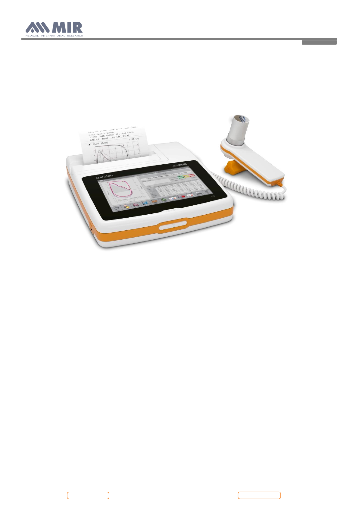
2. HARDWARE DESCRIPTION ..............................................................................................................................................................................................6
2.1. MAIN BOARD MODULE .....................................................................................................................................................................................................7
2.1.1. Charging controller for battery (U5 BQ2004) ...................................................................................................................................................................7
2.1.2. Room temperature sensor..................................................................................................................................................................................................8
2.1.3. USB communication port..................................................................................................................................................................................................8
2.1.4. Oximetry port .....................................................................................................................................................................................................................8
2.2. DISPLAY MODULE...............................................................................................................................................................................................................9
2.3. PRINTER MODULE .............................................................................................................................................................................................................9
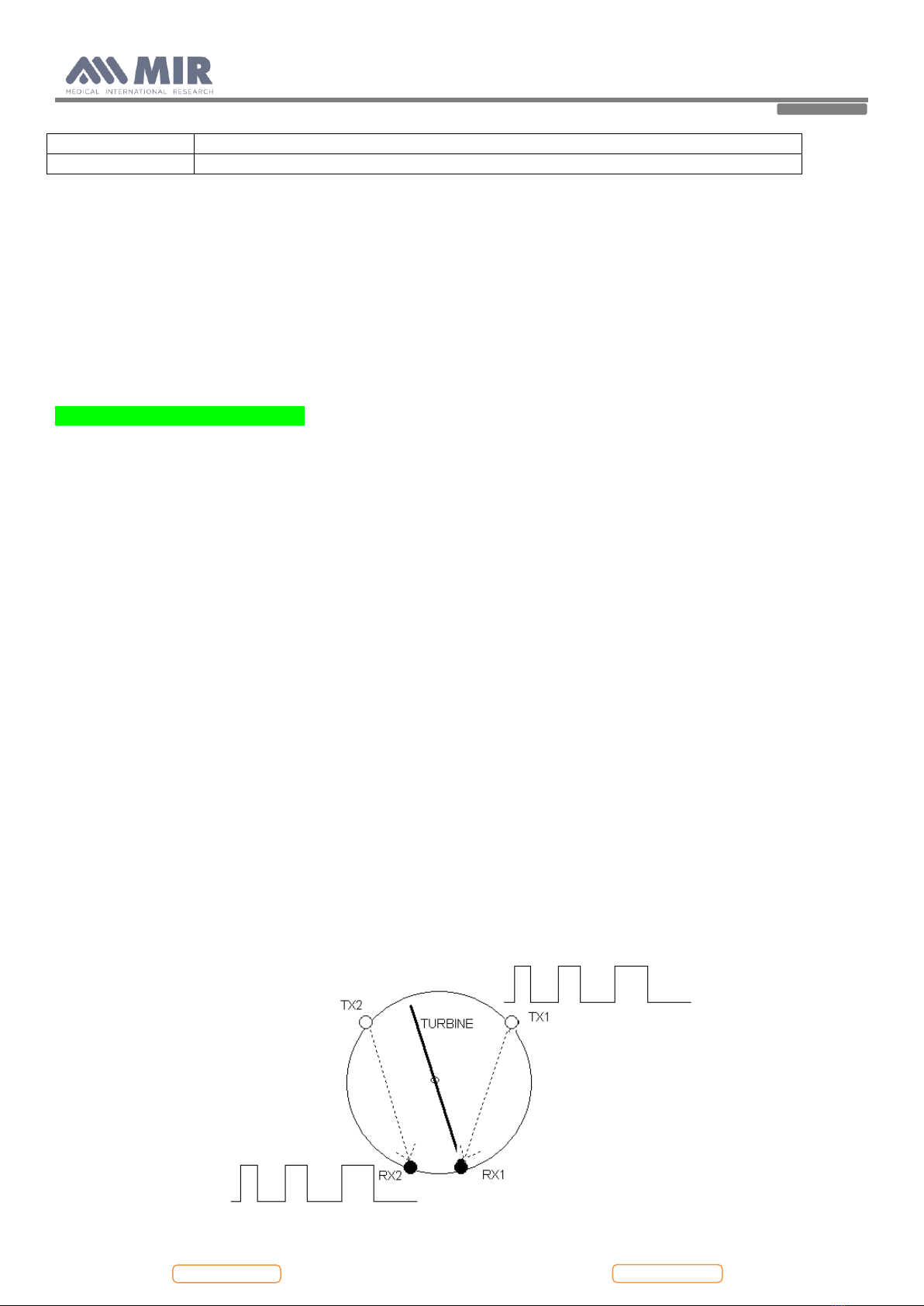
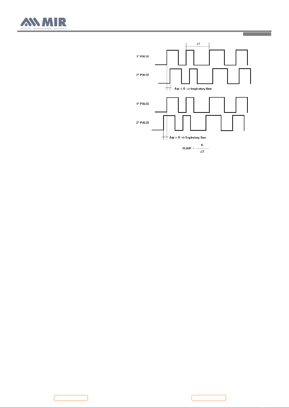
2.4. TURBINE FLOWMETER.....................................................................................................................................................................................................9
3. MAINTENANCE ................................................................................................................................................................................................................. 10
3.1. GENERAL............................................................................................................................................................................................................................. 10
3.2. TEST EQUIPMENT ............................................................................................................................................................................................................ 10
3.3. CHECKLIST.......................................................................................................................................................................................................................... 10
3.3.1. Functional test...................................................................................................................................................................................................................11
3.3.1.1. Self test...............................................................................................................................................................................................................................11
3.3.1.2. Software version ................................................................................................................................................................................................................11
4. REPLACEMENT PROCEDURES ......................................................................................................................................................................................11
4.1. General ....................................................................................................................................................................................................................................11
4.2. Cover....................................................................................................................................................................................................................................... 12
4.2.1. Opening the device .......................................................................................................................................................................................................... 12
4.3. PCBs and components .......................................................................................................................................................................................................... 13
4.3.1. Removing and replacing the display............................................................................................................................................................................... 13
4.3.2. Removing and replacing the battery pack ...................................................................................................................................................................... 14
4.3.3. Removing and replacing the thermal printer.................................................................................................................................................................. 15
4.3.4. Turbine............................................................................................................................................................................................................................. 15
4.3.4.1. Cleaning the reusable turbine.......................................................................................................................................................................................... 16
4.3.4.2. Calibration of the reusable turbine.................................................................................................................................................................................. 16
4.3.5. Internal software upgrade procedure .............................................................................................................................................................................. 16
4.4. Oximeter module ................................................................................................................................................................................................................... 18
4.4.1. Replacing of the oximetry module .................................................................................................................................................................................. 18
4.5. Testing procedures ................................................................................................................................................................................................................ 18
4.5.1. Testing procedures for devices with oximeter................................................................................................................................................................ 18
4.5.2. Testing procedures for devices without oximeter .......................................................................................................................................................... 22
5. SPARE PARTS....................................................................................................................................................................................................................... 24
5.1. ORDERING .......................................................................................................................................................................................................................... 24
5.2. DELIVERY............................................................................................................................................................................................................................ 24
5.2.1. Ordering PCB's................................................................................................................................................................................................................ 24
5.2.2. Warranty claims................................................................................................................................................................................................................ 24
5.3. RETURN SHIPMENTS ...................................................................................................................................................................................................... 24
6. TROUBLESHOOTING....................................................................................................................................................................................................... 25
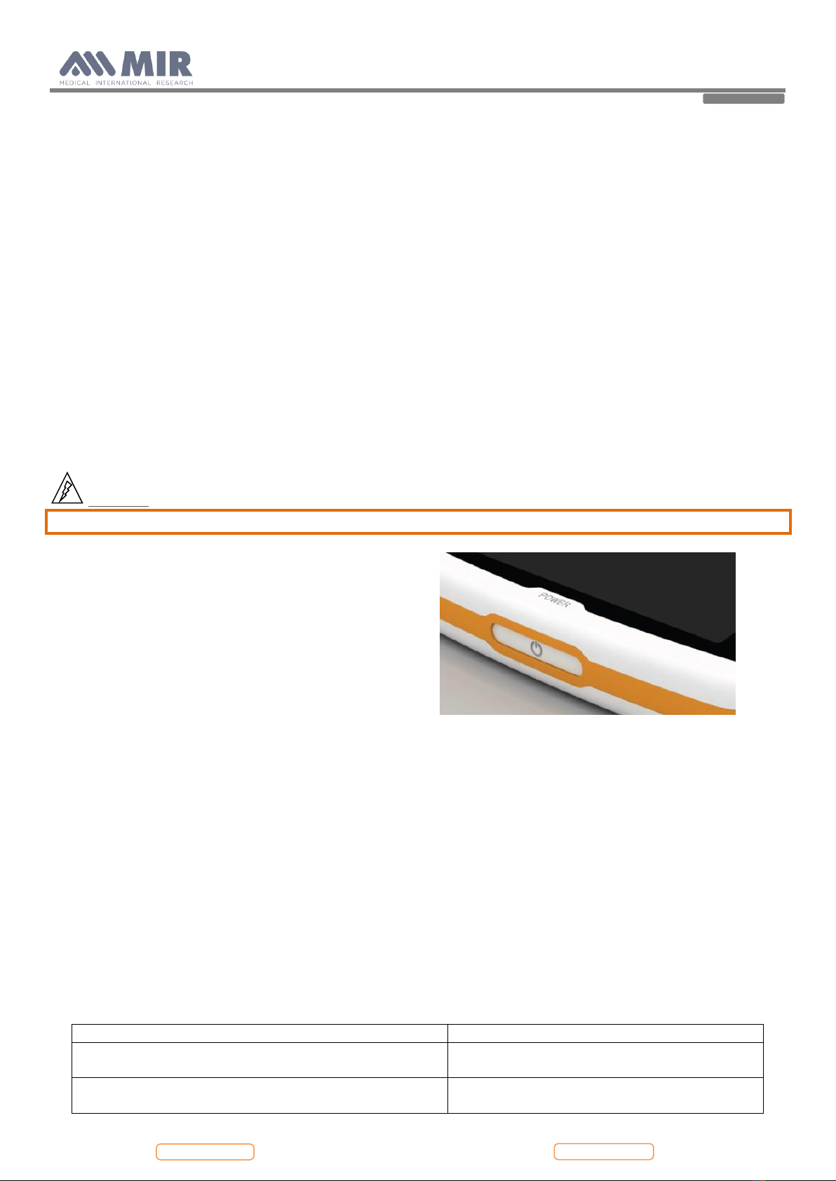
6.1. The device does not switch on .............................................................................................................................................................................................. 25
6.2. The display remains black..................................................................................................................................................................................................... 25
6.3. The battery is not working correctly ..................................................................................................................................................................................... 25
6.4. The device does not measure spirometry at all .................................................................................................................................................................... 26
6.5. The device does not measure spirometry correctly.............................................................................................................................................................. 26
6.6. The device does not measure oximetry at all ....................................................................................................................................................................... 26
6.7. The device does not measure oximetry correctly ................................................................................................................................................................. 26
6.8. The data communication via USB does not function .......................................................................................................................................................... 26
6.9. Index of components ............................................................................................................................................................................................................. 27
APPENDIX A: SPARE PARTS LIST .............................................................................................................................................................................................. 28
APPENDIX B: SERVICE INFO'S (Product Change Notes) ........................................................................................................................................................ 29
APPENDIX C.................................................................................................................................................................................................................................... 30
ANNEX.............................................................................................................................................................................................................................................. 33

Spirolab
Page 3 of 33
Rev.1.0
Service Guide
1. INTRODUCTION
1.1. INTRODUCTORY REMARKS
1.1.1. General Aspects
The spirometers from the product group MIR080 are marketed under the label Spirolab.
This manual has been written for technicians involved in the service of the Spirolab. Service can be carried out by the
service organization of the manufacturer or by any other technician authorized by MIR srl.
The manufacturer will not be held responsible for the results of maintenance or repairs by unauthorized persons.
1.1.2. Safety Aspects
Safe execution of the procedures in this manual requires technical experience and general knowledge of safety precautions.
Before you start any operation on the unit, you must have first read both the User and this Service
Manual.
Warnings, Cautions and Notes are used throughout this manual to bring special matters to the immediate attention of the
reader.
Warning The Warning concerns danger to the safety of the technician or user.
Caution The Caution draws attention to an action which may damage the equipment.
Note The Note points out a statement deserving more emphasis than the general text, but which does not
deserve a Warning or Caution.
Warning
In order to prevent unforeseen incidents, keep away from sensitive electronic devices. Inside the Spirolab there
are low voltages and very low currents, so these represent no danger for persons with experience and with a
general knowledge of safety precautions.
The sequence of steps in a procedure may also be important from the point of view of personal safety and prevention of
damage, therefore never change the sequence of steps or alter any procedure.
Warning
Batteries may explode if defective or damaged or disposed of in fire. Do not short-circuit the batteries!
1.1.3. Legal Aspects
This manual and the information herein are property of MIR srl (Rome, Italy).
Copying this manual in whole or in part is strictly forbidden.
MIR srl disclaims any responsibility for personal injury and/or damage to equipment caused by:
•negligence or disregard of a Warning or Caution
•deviation from any of the prescribed procedures
•execution of activities which are not prescribed
•ignorance of the general safety precautions for handling tools and the use of electricity
•incorrect or unreasonable use
1.1.4. Environmental Aspects
Please dispose properly of any items replaced, following all the local regulations.

Spirolab
Page 4 of 33
Rev.1.0
Service Guide
All components (housing, PCBs, batteries, electronic and disposable parts, etc.) must be disposed of according to the
relevant local regulations.
1.2. DATA REGISTRATION
1.2.1. Equipment and customer registration / Service file
From the point of view of safety and product liability the following data must be registered for each unit:
Equipment data
Model, REF code and serial number
Customer data
date of purchase
name and full address of the customer
Service data
log of all service activities
Configuration data
the actual configuration of the equipment (hardware and software versions)
The distributor (through their dealer and/or service organization, if any) is responsible for maintaining these records and
they must be able to provide these data when requested.
1.2.2. Configuration register
A configuration file gives the serial numbers and/or batch numbers of main sub-assemblies and/or important parts of
each unit. The parts listed in a configuration file are defined as registered parts. For example parts as mainboards, display,
batteries and internal software.
Note
MIR srl has the original configuration file of each unit sold. Any possible changes in the original configuration of
the supplied units must be filed and the distributor must be able to provide this data.
1.2.3. Product documentation
The documentation set for the Spirolab includes a User Manual. The User Manual is a recommended item for all service
engineers. The user manual is available in the following languages:
•English
•Spanish
•German
•French
•Italian
•Portuguese
1.2.4. Technical modifications
This publication could include technical inaccuracies or typographical errors. Changes are periodically made to the
information herein; these changes will be published as Service Info in appendix B of this Service Manual.
Note
Some functions described in this manual may not be activated in the present software or hardware version. For
detailed information, please refer to the User Manual.
1.2.5. Product evaluation
In order continuously to improve the quality of our products, MIR srl requests that the service organizations should report
any device issue which may be discovered. When the same issue regularly occurs or when a safety issue occurs, MIR srl
would like you to send us a product complaint report. The report must contain the name, the type of product, a detailed

Spirolab
Page 5 of 33
Rev.1.0
Service Guide
description of the problem, the frequency of the same problems, the quantity of sold equipment and your solution to the
problem (if any).
1.2.6. Additional Information
Please do not hesitate to contact MIR if you require additional information.
Manufacturer’s address:
MIR srl
Medical International Research
Via del Maggiolino, 125
00155 Rome
Italy
Tel.: +39/06/2275 4777
Fax.: +39/06/2275 4785
Email: [email protected]
1.2.7. Installation
Warning:
Before using Spirolab check internal battery charge level.
•turn the spirolab on, press then release the button on
the front of the unit.
1.3. GENERAL
Spirolab is an “open circuit system” for the measurement of inspiratory and expiratory lung function parameters and
oximetry values, such as pulse rate and SpO2. It is suitable for basic lung function analysis of the mechanical respiratory
tract parameters. Three different respiratory tests can be performed:
•the forced vital capacity test (FVC),
•the slow Vital Capacity test (VC/IVC)
•the Maximum Voluntary Ventilation test (MVV)
Spirolab has been designed and manufactured to ensure the highest level of safety and the unit fully complies with the
stringent international EN 60601-1 and EN 60601-1-2 standards.
1.3.1. Technical Data
1.3.1.1. Spirolab unit
Max. current inside the unit
400 mA (with LCD at the maximum lightness)
Internal batteries
NiMH rechargeable 7.2V battery pack (6
batteries, 1.2V each), 4000 mAh
Approval
CE 0476 EC mark for Medical Devices
FDA

Spirolab
Page 6 of 33
Rev.1.0
Service Guide
Dimensions
Main body 220x210x51 mm;
Weight
Central unit 1450 g (including battery pack)
Volume range
10 L
Flow range
± 16 L/s
Volume accuracy
± 3% or 50 mL
Flow accuracy
± 5% or 200 mL/s
Dynamic resistance at 12 L/s
< 0,5 cmH2O/L/s
Type of electrical protection
Class II device
Level of protection against direct or indirect contact
Category BF apparatus
Level of water ingress protection
IPX1 device, protected against water drops
Level of assurance of use in the presence of an anaesthetic
mix flammable with air or oxygen or protoxide of nitrogen
Apparatus not suitable
Conditions of use
Apparatus for repeated use
Storage conditions
Temperature: MIN -40 °C, MAX +70 °C
Humidity: MIN 10% RH; MAX 95%RH
Transport conditions
Temperature: MIN -40 °C, MAX + 70 °C
Humidity: MIN 10% RH; MAX 95%RH
Operating conditions
Temperature: MIN +10 °C, MAX +40 °C
Humidity: MIN 10% RH; MAX 95%RH
1.3.1.2. Battery charger
Model AC/DC 12W-N1EFM
1.4. STANDARDS APPLIED
•According to rule 10 of the European directive 93/42/CEE the device is classified as Class IIa
•EN 60601-1 Electronic medical apparatus. Part 1: General safety standards
•EN 60601-1-1 Electronic Medical apparatus. Part 1: General safety standards 1. Collateral standard: Safety requirements
for medical electronic systems
•EN 60601-1-2 Electronic medical apparatus. Part 1: General safety standards 2. Collateral standard: Electromagnetic
compatibility –Requirements and tests
•EN 60601-1-4 Electronic medical apparatus. Part 1: General safety standards 4. Collateral standards: Programmable
medical electronic systems
•UNI CEI EN ISO 14971 Medical devices: application of risk management to medical devices
•ATS/ERS TASK FORCE: Standardisation of lung function testing (volume 26/numbers 1-5/2005)
•Health Canada Medical Device Regulation: SOR-98-282
•SANS 451:2008 Spirometry —Generation of acceptable and repeatable spirograms FDA Regulations
•Japanese MHLW Ministerial Ordinance 169: 2004
2. HARDWARE DESCRIPTION
Because of the modular design of the Spirolab, the description is on a block diagram level.
BLOCK DIAGRAM

Spirolab
Page 7 of 33
Rev.1.0
Service Guide
2.1. MAIN BOARD MODULE
The main board module translates the input signal from the turbine flowmeter into spirometry values and compares them
with the predicted values calculated with the parameters age, sex, height, weight and ethnic group. Test results are
displayed on a LCD and can be printed on paper with an external printer. Spirometry test data are stored into memory and
are available for later use.
The main board module also makes a calculation using the oximetry input signal; from this signal collected at a 16
msec/frequency the percentage value of oxygen saturation in the blood and the heart beat values are obtained, which are
oximetry parameters.
The main board module includes:
-Main Microcontroller
-FLASH memory with device configuration and spirometry data
-FRAM/RTC with non volatile memory and real time clock
-Measuring controller for flow, volume and ambient temperature
-Ambient temperature sensor (to enable conversion from ATP to BTPS conditions).
-USB port
-Oximetry port
-Bluetooth module
2.1.1. Charging controller for battery (U5 BQ2004)
The charging controlling circuit used in the Spirolab ensures a charge and optimum condition of the battery providing
that the battery temperature and voltage are within the preset limits. Temperature, voltage and time are all monitored
throughout the charge process.
The charging process itself is automatically initiated in two situations:
1. After connecting the battery charger to the unit.
2. When the unit is switched on, the battery charger is connected and the voltage level of the battery is below a preset
limit. In this situation the LCD indicates the low battery status with one line in the battery indicator.
The fast charging process is terminated by any of the following:
-Battery voltage out of range (Maximum/Minimum)
-Battery temperature out of range (Maximum/Minimum)
-Maximum charging time (timeout = 5h:30min)
-Termination according to the charging mode, chosen by jumper JP2.

Spirolab
Page 8 of 33
Rev.1.0
Service Guide
Charging termination modes:
1. Temperature Arise Detection (T/t), JP1 jumper in the default position. The battery temperature increases more
quickly when the battery is fully charged. If the speed of temperature increase inside the battery pack exceeds a certain
value then the charging process is terminated. The charging controller (U5) samples the thermistor voltage (NTC)
every 34 sec., and compares it to the value measured two samples earlier. If the voltage has fallen 16mV 4mV or
more, the fast charge is terminated.
2. Peak Voltage Detection (PVD), JP1 jumper in the other possible position: The battery’s voltage decreases slightly
when it is fully charged. In this charging-mode, the microcontroller checks the battery voltage and terminates the
charging process in the event that the voltage on the battery pack decreases by more than the preset limit, that limit is
configured by the position of the jumper: In this mode, the battery’s voltage is the criteria for terminating the charging
process. If the voltage decreases by 36mV 4mV in 34 seconds this means that the battery is fully charged, and the
controller then terminates the charging process.
3. Decrease Voltage Detection (-V), no JP8 jumper. This mode is correspondent to the PVD-mode, but at higher
sensibility, because the charging process ends at a voltage decrease of 18mV 2mV in 34 seconds.
Caution
In case high power while charging is required (i.e. when printing), the battery’s voltage decreases. In this case
using the modes Peak voltage Detection or -V the charging process will be terminated, although the battery is
not fully charged.
The factory setting is designed for the T/t Termination mode and is not to be changed to avoid the above-
mentioned problems!
Charging phases:
1. After connecting the battery charger to the unit, the CHARGE_LED starts flashing for few seconds. In this period,
the battery is charged in pulses at a low frequency and the battery’s response is monitored. If the LED continues to
flash this shows that the battery’s temperature is out of range or the battery voltage is too low. In this case, the
controller enters the charge pending state and waits for both conditions to fall (temperature) or rise (voltage) within
their allowed limits. There is no time limit on the charge pending state; the charger remains in this state for as long as
the voltage or temperature conditions are outside of the allowed limits. If the voltage is too high, the controller goes to
the battery absent state and waits until a new charge cycle is started.
2. If everything is in order (battery temperature, temperature rising, battery voltage etc.) then the fast charging process
starts, the LED lights continuously. In the following 10 minutes, the battery is charged at a lower rate to initialize
slowly the chemical reaction inside the battery pack. After about 10 minutes, high-frequent pulses at the full current
rate of 1A charge the battery.
3. At the end of the regular charging process, the CHARGE_LED lights green continuously. Now it can be assumed that
the battery is fully charged.
4. If after completing the charging process the battery charger is still connected, a so-called Pulse-Trickle-Function is
activated that gives a very low charge to compensate the self-discharging of the battery while it is idle connected to the
charger.
2.1.2. Room temperature sensor
(IC7) DALLAS DS 18B20 to measure the ambient (room) temperature to enable the calculation of the BTPS conversion
factor.
2.1.3. USB communication port
Version 2.0.
2.1.4. Oximetry port
Many sensors can be used on Spirolab
based on the type of test to be performed and on the patient characteristics.
The manufacturer provides the most frequently used sensor with the device, which has the following features:

Spirolab
Page 9 of 33
Rev.1.0
Service Guide
mechanical part
finger
electrical part
two light emitting diodes (LEDs), one emits in the visible spectre and one infrared
Both lights then pass through the finger and are “read” by the receiver. As these lights pass through the finger, a
proportion of the light is absorbed by the blood and by the soft tissue, in function of the concentration of haemoglobin.
The quantity of light absorbed, at each frequency, depends on the degree of oxygenation of the haemoglobin inside the
soft tissue.
2.2. DISPLAY MODULE
The display module shows patient data, user set parameters and test results..
It is connected with:
40-pin flat-cable for digital connection (code 512584)
The lamp controller (IC6) MAX 8822
2.3. PRINTER MODULE
The printer module gives a printout of the patient data and spirometric/oxymetric results. The printer is a thermal printer
and requires thermal printing paper.
The printer is connected to the mainboard via 3 cables:
-a 4-pin flat-cable for driving the motor for paper advance
-a 4-pin flat-cable for the sensor, that checks that paper is inserted
-28-pin flat-cable for supply, data transmission and checking the temperature of the printer head, to avoid overheating.
2.4. TURBINE FLOWMETER
The sensor for measuring flow and volume is similar to the model already used in other spirometers produced by MIR
(Series MIR 040 Mod. Spirodoc, MIR024_REV2 Mod. Spirobank G USB, etc).
The turbine flowmeter consists of one mechanical and two electrical parts:
Mechanical parts:
-turbine
Electrical parts:
-Two pairs of infrared transmitters/receivers positioned as shown below.
-A signal conditioning circuit to rectify the output signal from the two infrared light receivers.
The rotation of the rotor causes the interruption of the infrared beam, thus creating a pulse signal which has a frequency
directly proportional to the flow.
The measurement of the air flow which passes through the tube is therefore proportional to the number of interruptions
of the infrared beam.

Spirolab
Page 10 of 33
Rev.1.0
Service Guide
The phase difference (positive or negative)
between the signals from each of the two infrared
receivers (RX1 and RX2) depends upon the direction
of rotation of the moving rotor and therefore supply
the information of the direction of the air flow
(expiration or inspiration).
In detail, > 0 for expiratory flow, < 0 for
inspiratory flow.
The two pulse trains are squared by a Schmitt trigger
(LMV932MM on MiniFlowmeter) and then sent to
two input ports of the microprocessor (IC17
CP3BT26, pins 38 and 36).
The main microprocessor has the possibility to switch
all the peripheral ports on or off, including the
turbine.
3. MAINTENANCE
3.1. GENERAL
We recommend checking the Spirolab on an annual basis.
For cleaning of the Spirolab
and the accessories please see the User Manual.
3.2. TEST EQUIPMENT
For the repair and maintenance procedures of the Spirolab the following test equipment and accessories are required:
-Complete set of precision engineering tools (including 2.5 mm allen key and cross-screwdriver)
-Calibration syringe (3L is recommended)
-Digital multimeter, at least 3½ digits, accuracy better than 1%.
-Oscilloscope
-Digital Thermometer
-PC
-winspiroPRO Software Installation CD
-USB port connection cable
-Oximeter sensor (MIR code 919024)
-Hot Glue Gun
-3 mm double-sided adhesive tape
-Welder
If a problem cannot be solved with the present equipment and suitable instruments are not available, please send the
Spirolab to the manufacturer to carry out the service.
3.3. CHECKLIST
The following procedures must be carried out during an inspection and/or after every repair:
•Modifications, if any, must be noted on the “Service Info” sheets. See Appendix B of this manual for further
information.
•Visual inspection. Check the electrical connection for safety and check that all components are properly fastened.
•Check that all accessories do not present any visible damage.
•Functional test (see Paragraph 3.3.1)
•File a copy of all service activities.

Spirolab
Page 11 of 33
Rev.1.0
Service Guide
3.3.1. Functional test
3.3.1.1. Self test
Switch on the equipment. Spirolab will carry out the so-called self-test for approx 3 seconds. It is assumed that when the
self-test is passed all functions of Spirolab are okay.
Any severe malfunction (if any) will be reported on the display.
Switch off Spirolab.
3.3.1.2. Software version
To check the software version installed on the device,
switch on Spirolab pressing and releasing the
ON/OFF key, wait for the first screen to appear; the
software version is found as indicated in the image
alongside.
4. REPLACEMENT PROCEDURES
4.1. General
When handling sensitive static devices such as the main board of the Spirolab the following precautions should be
observed:
-Persons should be earthed by means of a wrist strap.
-Ground all electrical equipment, workbench etc.
Also make sure that you have not left any tools inside and all screws including their washers are again fixed in the original
place.
Note
Where not otherwise indicated, the reinstallation of a part is in reverse order of the removal procedure.
After every repair a functional test must be performed.
Caution
If any soldering (especially on SMD-parts) is to be made, make sure that your tools are suitable for such
precision work.

Spirolab
Page 12 of 33
Rev.1.0
Service Guide
4.2. Cover
The Spirolab case consists of several parts as illustrated in the image beside.
The display is housed inside its casing which is made up of two parts held together with three screws.
Code 300600
Code 300601
Code 300602
Code 300603
Code 300604
Code 300605
Code 300608
Code 300607
4.2.1. Opening the device
To open Spirolab:
Switch off the device Place the device on a flat surface with bottom part
face-up.
Unscrew the screws in the holes highlighted in the image alongside.
Turn upside down the device and remove the thermal paper cover sliding it
to the back of the device.
Remove the upper case from the central case starting from the back side;
put the nails between the two cases and remove gently the upper case.
Pay attention to the display cables which are connected to the main board
Remove the cable red and white as in the image alongside.
Now it is possible to open some more the upper case and the other two
cables will be visible.
Open the white flat cable connector and the flat will exit easily.
At the end remove the other flat opening the brown connector.
In this way the upper case with the display are completely removed.

Spirolab
Page 13 of 33
Rev.1.0
Service Guide
Remove the middle case from the lower case: it is necessary to remove the screw in the upper left corner of the middle
case.
4.3. PCBs and components
4.3.1. Removing and replacing the display
Open Spirolab as described in Paragraph 4.2.1; remove the
damaged display from the upper casing. First of all remove
the white flat cable from the connector on the rear side of
the display (see image), then remove the nuts and the
washers from the upper case.
Now the damaged display can be removed from the case.
Apply a new one paying attention to insert the red and
white cable in the hole. Apply the nuts and the washers to
the screws
Check if the display is aligned with the housing and then
close firmly the nuts.
Insert the white flat in the connector and make sure that the
black part of the connector is firmly closed above the flat.
Apply a bit of hot glue to the connector to block the
opening of it.

Spirolab
Page 14 of 33
Rev.1.0
Service Guide
Apply a thick adhesive on the brown flat as in the image
below. It has the function to improve the seal when it is
inserted in the connector.
Connect the two flat cables of the display to the PCB.
At this time it is possible to close the device following the instruction described in point 4.2.1 in reverse order.
4.3.2. Removing and replacing the battery pack
Open Spirolab as described in Paragraph 4.2.1.
To correctly replace the battery pack completely remove
the PCB from the lower casing.
Open jumper JP1.
Unsolder the two connectors from the PCB on both sides.
Cut the plastic casing of the battery pack in order to
remove the battery elements. In this way it will be more
simple to remove the double sided tape which allows to
keep firmly the battery pack to the main board.
Replace the battery with a new one.
Apply the double sided tape as in the image alongside.
Insert the positive and then the negative pole in their proper place on the PCB. Place the battery pack so that the adhesive
tape is towards the PCB and press to firmly seal it to the PCB.
For a better hold it is recommended to also solder the other side of the PCB in order to provide more protection in case of
dropping or vibrations.
Caution
Insert the connector in the correct position all the way to the stop. Do not force the connector.
Place the cable of the battery bended as shown in the image above; the cable must be blocked between the
battery and the lower casing.
Warning
Handle battery pack with care. Contact between battery poles with the circuit board can cause permanent
damage to the circuit board itself.
During soldering operations avoid any contact whatsoever between battery poles and components of the circuit
board.
Before to close the device keep in mind to close the jumper JP1.
Close the device as described in point 4.2.1.
Note
Batteries must be disposed of properly, according to the local regulations.
double sided tape
double sided tape

Spirolab
Page 15 of 33
Rev.1.0
Service Guide
4.3.3. Removing and replacing the thermal printer
Disconnect the printer by unscrewing the four screws as
highlighted in the image.
Disconnect the connectors underneath, paying attention to
not pull the flat cable without having first opened the clips
The screw in the bottom right position must also block the
metal clip, see image below:
Caution
While applying the self-tapping screws, pay attention to the position of the flat cables underneath: make sure
they are precisely and correctly positioned.
4.3.4. Turbine
There are two types of flow and volume measurement sensors used on Spirolab, single-patient disposable and reusable.
Note
The Spirolab turbine measurement system is calibrated in the factory and does not require any adjustments or
calibrations.
Warning
Disposable Turbine
If you are going to perform the spirometry test with a “single-
patient” disposable turbine it is important to use a new turbine for
every new patient. The characteristics, accuracy and the hygiene of
the disposable turbine can only be guaranteed if it has been
conserved beforehand in its original sealed packaging.
The disposable turbine is made of plastic and its disposal after use
should adhere to the local authority guidelines / norms.
Reusable Turbine
The correct functioning of the re-usable turbine can only be
guaranteed if it has been cleaned in the correct manner and is free
from foreign bodies which could alter its movement. If the turbine
has not been cleaned sufficiently this could cause cross
contamination from one patient to another. Periodic cleaning
should only be done when the instrument is for personal use and
will only be used by one patient. The cleaning of the turbine
should be done following the guidelines in the User’s Manual.
The following information applies to both turbine models.
Do not expose the turbine to a direct jet of water or air, and avoid contact with high temperature liquids.
Do not allow dust or foreign bodies to enter the turbine sensor, in order to avoid incorrect functioning and possible
damage. The presence of any impurities (such as hair, sputum, threads etc.) within the body of the turbine sensor may
seriously compromise the accuracy of the measurements.

Spirolab
Page 16 of 33
Rev.1.0
Service Guide
The turbines ensure high precision in measurements and have the great advantage of requiring no periodic calibration. In
order to maintain the characteristics of the turbine a simple cleaning is required prior to each use (only for the reusable
turbine). This operation will also guarantee perfect hygiene and the highest possible safety conditions for the patients.
Cleaning of the disposable turbine is not required, as it is supplied clean in a sealed plastic bag. It must be disposed of after
use.
4.3.4.1. Cleaning the reusable turbine
Cleaning of the disposable turbine is not required, as it is supplied clean in a sealed plastic bag. It must be disposed of after
use.
Turbine operation check:
•Turn on SPIROLAB and setup the device to perform a spirometry test (for example FVC).
•Hold the SPIROLAB with one hand and move it slowly sideways, having the air pass through the turbine.
•If the rotor spins properly the device will emit a series of acoustic signals “beeps”. The beeping frequency is a function
of the air flow passing through the turbine.
•If no beeps are heard while moving the device, proceed to clean the turbine
CAUTION
Periodically check the inside of the turbine to ensure that there are no impurities, corpuscles, or any foreign
matter like hairs which could inadvertently block or even slow down the mobile equipment in the turbine and as
a consequence compromise spirometry measurement accuracy.
To clean the reusable turbine, first remove it by pulling it gently from the Spirolab turning it anti-clockwise and pressing
lightly. It can be helpful to push it gently from underneath with one finger from the bottom of the turbine to lift it out of
its housing.
Immerse the turbine in a cold liquid solution and move it within the liquid to remove any impurities which may be
deposited inside. Leave the turbine immersed for the time specified in the instruction of the solution.
Rinse the turbine by immerging it in clean water (not hot).
Shake off the excess water from the turbine and leave it to dry, standing it vertically on a dry surface.
To ensure that the turbine is functioning correctly before replacing it inside the instrument, it is good practice to make a
visual check of the rotation blade. Placing the turbine tube horizontally and moving it gently from left to right and vice
versa, the rotation blade (rotor) must rotate freely. Otherwise, accurate measurement is no longer guaranteed and the
turbine must be replaced.
Once the turbine has been cleaned insert the turbine tube in its place following the instructions indicated by the closed
lock symbol printed on the plastic casing of the Spirolab.
To insert the turbine correctly push it and then turn it clockwise until it reaches the stop, which ensures that the tube has
been blocked inside the casing.
4.3.4.2. Calibration of the reusable turbine
See instructions in the Calibration section of the User Manual of the device.
The turbines used on Spirolab do not require periodic calibration as they are already calibrated.
4.3.5. Internal software upgrade procedure
In order to upgrade the software winspiroPRO must already be installed and the PC must have an internet connection for
downloading the upgrades and firmware of the Spirolab from www.spirometry.com.
Launch winspiroPRO on the PC and connect Spirolab
to the PC using the USB cable.

Spirolab
Page 17 of 33
Rev.1.0
Service Guide
winspiroPRO can check the correct functioning of the USB port
from the “options” menu; before downloading any newer releases
make sure that the device is correctly connected to the PC software,
the software will automatically recognize the device if it has already
been connected to the PC and then carry out the following
instructions.
To check the connection between the device and the PC, check the
correct functioning from the “options, communication” menu. On
the display of Spirolab appears the following message:
External control
To download the new internal software version
click on "Tools" menu, and then on "Upgrade
Device Internal Software"
This wizard helps the user to select the method used to connect the
device to the PC and then, with the “TEST” icon, the user can check
the connection (see image).
Search for the .tsk file to be downloaded into the spirometer. Choose
either auto-install or manual file search; browse system resources
through list of folders, select .tsk file and then click on Next.

Spirolab
Page 18 of 33
Rev.1.0
Service Guide
From the “Select file .tsk” search window select the firmware of your
device; click on the Spirolab folder and then on the selected file to
automatically launch the upgrading procedure of the internal software
of the spirometer.
4.4. Oximeter module
To check the oximetry module used on the device, refer to Annex 4.
CAUTION
Make sure before operating on the oximetry module to
switch off the device or disconnect the battery pack.
4.4.1. Replacing of the oximetry module
Open the device as described in point 4.2.1. The visible face of the PCB shows near
the micro USB connector the housing of the oximetry module.
Remove the oximetry module using the hands.
CAUTION
The module is fixed to the PCB so move gently until the module is
completely removed.
Replace the oximetry module.
To attach the oximetry module to the PCB, it is recommended to apply an adhesive
in the space between the PCB and the highest micro on the oximetry module (placed
in the face not visible).
Close the device as in point 4.2.1 in reverse order.
4.5. Testing procedures
After making all repairs described in the previous paragraphs, correct functioning tests must be performed on both the
Hardware and Software.
Devices with oximeter and devices without oximeter have their own specific testing procedures.
4.5.1. Testing procedures for devices with oximeter
The following checks must be carried out on each device:

Spirolab
Page 19 of 33
Rev.1.2
Service Guide
Table 1
TESTS ON PCB MIR080 WITH OXIMETER
Test
Procedure
Test method
Instrument
Expected result
Check battery pack application
there should be applied the double sided tape on the
battery pack
Visual
\
The doubled sided adhesives must be applied between
the PCB and the battery pack
Block of PCB on the lower case
There should be applied 11 screws and washers in the
special holes
Visual
\
The screws should be all correctly screwed
Display application on the upper case
There should be applied 6 nuts and showers between
display and case
Visual
\
The nuts should be all correctly screwed
White flat display application to the display
There should be applied and blocked with hot glue
Visual
\
Presence of hot glue on the connector
Brown flat display application
There should be applied a thick adhesive to the flat
Visual
\
Presence of a thick adhesive on the flat
Blocking of display flats
Application of thick adhesive on connectors J13 and
CONN1
Visual
\
Presence of a thick adhesive on the two connectors
Blocking of oximetry module
Check that the oximetry module has been correctly
applied
Visual
\
The doubled sided adhesives must be applied between
the PCB and the greatest micro on the oximetry module

Spirolab
Page 20 of 33
Rev.1.2
Service Guide
CHECKS ON MAIN CASING OF THE ASSEMBLED DEVICE
Table 2
Test
Procedure
Test method
Instrument
Expected results
Temperature
Check that the temperature corresponds to the BTPS*
Instrument
Thermometer
Temperature equal to thermometer
reading +/- 1 °C
Date and time
Set time and date (see User Manual)
Visual/
Quantitative
\
The set parameters must remain as
configured
Bluetooth
Carry out search for enabled devices
Visual
\
Device shoulb be recognized by the
PC used
Auto-off
switch on the device and leave it for 6 minutes
Visual
\
After 6 minutes the device switches off
Display
Switch on the device and check screen shots
Visual
\
All pixels must work correctly
* The BTPS appears on the printout of a spirometry test
Other manuals for Spirolab
2
Table of contents
Other MIR Medical Equipment manuals
Popular Medical Equipment manuals by other brands

VISIOMED
VISIOMED KINECARE VM-WT1 Tens/EMS Instructions for use

Daavlin
Daavlin ClearLink 4 Series Operation manual

Breas
Breas Vivo 50 User instruction

Guardian
Guardian Guardian Easytrack System 900-0880 Installation and instruction manual

laerdal
laerdal LCSU 4 Directions for use

Medisa
Medisa Majestic II User manual and technical description