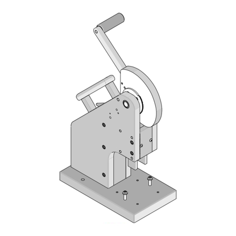
molex 90327 Series User manual

Manual Hand Tool for Picoflex® PF-50 Connectors
Doc No: ATS-6 00810 0 Release Date: 06-28-05 UNCONTROLLED COPY Page 1 of 6
Revision: F Revision Date: 07-17-12
MANUAL
HAND TOOL
Application Tooling
Specification Sheet Order No. 9008-1090
FEATURES
A full cycle ratcheting hand tool ensures complete terminations
This tool is intended for prototype, low volume, and field repair applications
Capable of Feed-Thru and Feed –To termination.
Hand Tool measures 200mm x 150mm x 50mm and weighs 1.65 lb (0.75kg)
SCOPE
Products: 1.27mm Pitch Picoflex® PF-50, Low Profile, IDT Receptacle 4 to 26 circuits, terminates 26 or 28 AWG
flat cable. (1.00mm max. thickness).
Series No.
Circuit Size
Connector Order Number
0327
4
0327
-
0304
0327
-
0351
0327
-
0352
0327
-
0353
0327
-
0354
0327
-
3
304
0327
-
3
351
0327
-
3
352
0327
-
3
353
0327
-
3
354
0327
-
5
304
0327
-
5
351
0327
-
5
352
0327
-
5
353
0327
-
5
354
6
0327
-
0306
0327
-
0355
0327
-
0356
0327
-
0357
0327
-
0358
0327
-
3
306
0327
-
3
355
0327
-
3
356
0327
-
3
357
0327
-
3
358
0327
-
5
306
0327
-
5
355
0327
-
5
356
0327
-
5
357
0327
-
5
358
8
0327
-
0308
0327
-
035
0327
-
0360
0327
-
0361
0327
-
0362
0327
-
3
308
0327
-
3
35
0327
-
3
360
0327
-
3
361
0327
-
3
362
0327
-
5
308
0327
-
5
35
0327
-
5
360
0327
-
5
361
0327
-
5
362
10
0327
-
0310
0327
-
0363
0327
-
0364
0327
-
0365
0327
-
0366
0327
-
3
310
0327
-
3
363
0327
-
3
364
0327
-
3
365
0327
-
3
366
0327
-
5
310
0327
-
5
363
0327
-
5
364
0327
-
5
365
0327
-
5
366
12
0327
-
0312
0327
-
0367
0327
-
0368
0327
-
036
0327
-
0370
0327
-
3
312
0327
-
3
367
0327
-
3
368
0327
-
3
36
0327
-
3
370
0
327
-
5
312
0327
-
5
367
0327
-
5
368
0327
-
5
36
0327
-
5
370
14
0327
-
0314
0327
-
0371
0327
-
0372
0327
-
0373
0327
-
0374
0327
-
3
314
0327
-
3
371
0327
-
3
372
0327
-
3
373
0327
-
3
374
0327
-
5
314
0327
-
5
371
0327
-
5
372
0327
-
5
373
0327
-
5
374
16
0327
-
0316
0
327
-
0375
0327
-
0376
0327
-
0377
0327
-
0378
0327
-
3
316
0327
-
3
375
0327
-
3
376
0327
-
3
377
0327
-
3
378
0327
-
5
316
0327
-
5
375
0327
-
5
376
0327
-
5
377
0327
-
5
378
18
0327
-
0318
0327
-
037
0327
-
0380
0327
-
0381
0327
-
0382
0327
-
3
318
0327
-
3
37
0327
-
3
380
0327
-
3
381
0327
-
3
382
0327
-
5
318
0327
-
5
37
0327
-
5
380
0327
-
5
381
0327
-
5
382
20
0327
-
0320
0327
-
0383
0327
-
0384
0327
-
0385
0327
-
0386
0327
-
3
320
0327
-
3
383
0327
-
3
384
0327
-
3
385
0327
-
3
386
0327
-
5
320
0327
-
5
383
0327
-
5
384
0327
-
5
385
0327
-
5
386
22
0327
-
0322
0327
-
03
1
0327
-
03
2
0327
-
03 3
0327
-
03
4
0327
-
3
322
0327
-
3
3
1
0327
-
3
3
2
0327
-
3
3 3
0327
-
3
3
4
0327
-
5
322
0327
-
5
3
1
0327
-
5
3
2
0327
-
5
3 3
0327
-
5
3
4

Manual Hand Tool for Picoflex® PF-50 Connectors
Doc No: ATS-6 00810 0 Release Date: 06-28-05 UNCONTROLLED COPY Page 2 of 6
Revision: F Revision Date: 07-17-12
Series No.
Circuit Size
Connector Order Number
24
0327
-
0324
0327
-
03
5
0327
-
03
6
0327
-
03 7
0327
-
03
8
0327
-
3
324
0327
-
3
3
5
0327
-
3
3
6
0327
-
3
3 7
0327
-
3
3
8
0327
-
5
324
0327
-
5
3
5
0327
-
5
3
6
0327
-
5
3 7
0327
-
5
3
8
26
0327
-
0326
0327
-
0387
0327
-
0388
0327
-
038
0327
-
03 0
0327
-
3
326
0327
-
3
387
0327
-
3
388
0327
-
3
38
0327
-
3
3 0
0327
-
5
326
0327
-
5
387
032
7
-
5
388
0327
-
5
38
0327
-
5
3 0
0584
4
0584
-
1304
0584
-
1404
0584
-
2304
0584
-
2404
0584
-
304
0584
-
404
6
0584
-
1306
0584
-
1406
0584
-
2306
0584
-
2406
0584
-
306
0584
-
406
8
0584
-
1308
0584
-
1408
0584
-
2308
0584
-
2408
0584
-
308
0584
-
408
10
058
4
-
1310
0584
-
1410
0584
-
2310
0584
-
2410
0584
-
310
0584
-
410
12
0584
-
1312
0584
-
1412
0584
-
2312
0584
-
2412
0584
-
312
0584
-
412
14
0584
-
1314
0584
-
1414
0584
-
2314
0584
-
2414
0584
-
314
0584
-
414
16
0584
-
1316
0584
-
1416
0584
-
2316
0584
-
2416
05
84
-
316
0584
-
416
18
0584
-
1318
0584
-
1418
0584
-
2318
0584
-
2418
0584
-
318
0584
-
418
20
0584
-
1320
0584
-
1420
0584
-
2320
0584
-
2420
0584
-
320
0584
-
420
22
0584
-
1322
0584
-
1422
0584
-
2322
0584
-
2422
0584
-
322
0584
-
422
24
0584
-
1322
0584
-
14
24
0584
-
2324
0584
-
2424
0584
-
324
0584
-
422
26
0584
-
1322
0584
-
1426
0584
-
2326
0584
-
2426
0584
-
326
0584
-
422
1577
4
1577
-
0304
1577
-
1304
1577
-
2304
6
1577
-
0306
1577
-
1306
1577
-
2306
8
1577
-
0308
1577
-
1308
1577
-
2308
10
1577
-
03
10
1577
-
1310
1577
-
2310
12
1577
-
0312
1577
-
1312
1577
-
2312
14
1577
-
0314
1577
-
1314
1577
-
2314
16
1577
-
0316
1577
-
1316
1577
-
2316
18
1577
-
0318
1577
-
1318
1577
-
2318
20
1577
-
0320
1577
-
1320
1577
-
2320
22
1577
-
0322
1577
-
1
322
1577
-
2322
24
1577
-
0324
1577
-
1324
1577
-
2324
26
1577
-
0326
1577
-
1326
1577
-
2326
Make sure work area is clean and dry and wear approved eye protection.
SET-UP
Before attempting to terminate any connectors, make sure the insertion blades are correctly placed into the
pusher of the hand tool.
The insertion blades are marked with the connector series numbers on each side. Before using the hand tool
check to make sure the connector series being used is marked on the blades facing out. See Figure 1.
Open the tool by squeezing the handles together, at the end of the closing stroke, the ratchet mechanism will
release the handles, and the hand tool will spring open.
If the orientations of the insertion blades need to be changed follow the steps below:
1. Loosen and remove the M4 BHCS from one side of the hand tool.
2. Remove the guide plate.
3. Pull off the insertion blade from the support plate.
4. Turn the blade 1800 and reinstall with the correct marking facing out.
5. Reinstall the guide plate and the M4 BHCS.
6. Repeat steps 1 thru 5 for the on the opposite side of the tool.

Manual Hand Tool for Picoflex® PF-50 Connectors
Doc No: ATS-6 00810 0 Release Date: 06-28-05 UNCONTROLLED COPY Page 3 of 6
Revision: F Revision Date: 07-17-12
FRAME
Figure 1
CONNECTOR SERIES MARKING
FACING OUT FOR CONNECTORS
BEING TERMINATED
INSERTION BLADE
CONNECTOR SERIES MARKING
FACING IN FOR CONNECTORS
NOT TERMINATED
INSERTION
BLADE
TRACK
SUPPORT
PLATE
PUSHER
GUIDE PLATE (2)
M4 BHCS (2)
OPERATION
1. Open the hand tool.
2. Slide the connector into the track and push until it stops against
the stop screw. (Check connector orientation). See Figure 2.
3. For Feed-To Harnesses, insert the cable into the connector until
it stops. For Feed-Thru Harnesses push through to pre-set mark
on the cable. See Figure 3
4. With the connector seated in track correctly, squeeze the tool
handles together until the full cycle ratchet releases. If the
handles become jammed, see Missed Terminations or Jams
Section.
5. Release the tool handles and let the tool open completely.
6. Remove the terminated connector from the nest.
ADJUSTMENTS
Connector Stop Screw
The stop screw is used to align the connector’s terminals to the teeth on the insertion blade. This should not
require adjustment.
If adjustment is necessary, loosen the lock nut on the stop screw and turn the screw as needed to align the
terminals to the insertion blade teeth. Remember to tighten the locknut after adjustment.
Figure 2
CONNECTOR
CIRCUITS
CONNECTOR
STOP SCREW
TRACK
CABLE

Manual Hand Tool for Picoflex® PF-50 Connectors
Doc No: ATS-6 00810 0 Release Date: 06-28-05 UNCONTROLLED COPY Page 4 of 6
Revision: F Revision Date: 07-17-12
Figure 3
CABLE
TRACK
BRACKET
FEED
-
TO HARNESS
M3 SHCS
TRACK
BRACKET
FEED
-
THRU HARNESS
CABLE
Cable Stop
The bracket on the back of the track is adjustable for Feed-To and Feed-Thru harnesses.
1. For Feed-To harnesses the bracket should fit flush and inside the track. See Figure 3.
2. For Feed-Thru harnesses unscrew the M3 SHCS.
3. Rotate the bracket 1800.
4. Tighten the M3 SHCS. See Figure 3.
Maintenance
It is recommended that each operator of the tool be made aware of, and responsible for, the following
maintenance steps:
1. Disassemble the metal tool frame by removing the screws and pulling off the plastic handle. Remove dust,
moisture, and other contaminants with a clean brush, or soft, lint free cloth.
2. Do not use any abrasive materials that could damage the tool.
3. Make certain all pins; pivot points and bearing surfaces are protected with a thin coat of high quality machine
oil. Do not oil excessively. Light oil used at the pivot points every 5,000 terminations will significantly enhance
the tool life.
4. Wipe excess oil from hand tool, particularly from termination area.
Missed Terminations or Jams
Should this tool ever become stuck or jammed in a partially closed position, DO NOT
force the handles open or closed. The tool will open easily by pressing the ratchet
release lever up. See Figure 4.
How to Adjust Tool Preload
It may be necessary over the life of the tool to adjust tool handle preload force.
Listed below are the steps required to adjust the force of the hand tool to obtain the
proper termination conditions:
1. Remove the 2mm locking screw from the numbered adjusting wheel using a
screw driver. See Figure 4.
RATCHET
RELEASE LEVER
Figure 4
Manual Hand Tool for Picoflex® PF-50 Connectors
Doc No: ATS-6 00810 0 Release Date: 06-28-05 UNCONTROLLED COPY Page 5 of 6
Revision: F Revision Date: 07-17-12
NUMBERED
ADJUSTMENT
WHEEL
Figure 5
TURN CLOCKWISE (CW) OR
COUNTER CLOCKWISE (CCW)
TO ADJUST THE PRE-LOAD
TURN WITH A SMALL
SCREW DRIVER
REMOVE THE 2MM LOCKING SCREW
2. Using the same screw driver turn the adjustment wheel to the next highest number.
Note: The odd numbers are in clockwise (CW) direction and the even numbers are counter clockwise (CCW).
3. Example: If the preload is set at number 5, then to increase the preload, turn the adjustment wheel until the 6th
position is located over the 2mm locking screw tapped hole. If it is necessary to move to the 7th position, then
the adjustment wheel should be turned clockwise (CW) until the 7th position is over the 2mm locking screw
tapped hole.
4. Replace the 2mm locking screw, aligning the nearest notch in the setting wheel to locking screw.
5. Check the termination specifications after the tool handle preload force is adjusted. Repeat these steps until
the desired result is obtained.
Warranty
This tool is for electrical termination purposes only. All tools are warranted to be free of manufacturing defects for
a period of 30 days. Should such a defect occur, we will repair or exchange the tool free of charge. This repair or
exchange will not be applicable to altered, misused, or damaged tools. This tool is designed for hand use only.
Any clamping, fixturing, or use of handle extensions voids this warranty.
CAUTION: Molex crimp specifications are valid only when used with Molex terminals and tooling.
CAUTIONS:
1. Manually powered hand tools are intended for low volume or field repair. This tool is NOT intended for
production use. Repetitive use of this tool should be avoided.
2. Insulated rubber handles are not protection against electrical shock. NEVER perform crimps on active
electrical circuits.
3. Wear eye protection at all times.
4. Use only the Molex terminals specified for crimping with this tool.

Manual Hand Tool for Picoflex® PF-50 Connectors
Doc No: ATS-6 00810 0 Release Date: 06-28-05 UNCONTROLLED COPY Page 6 of 6
Revision: F Revision Date: 07-17-12
3
Figure
1
2
4
9
8
(2)
7
7
5
2
PARTS LIST
Manual Hand Tool 9008
-
1090
Item
Order No
Engineering No
Description
Quantity
Perishable Tooling
1
6 008
-
1084
6 008
-
1084
Support Plate
1
2
6 008
-
10 3
6 008
-
10 3
Insertion Blade
2
3
6 008
-
0 70
6 008
-
0
70
Spring (Main)
1
4
6 008
-
0 71
6 008
-
0 71
Spring (Ratchet)
1
5
6 008
-
0 72
6 008
-
0 72
Adjuster Wheel
1
Other Components
6
6 008
-
0703
6 008
-
0703
Bracket
R
EF
7
6 008
-
10 5
6 008
-
10 5
Guide Plate
R
EF
Hardware
8
N/A
N/A
M3 X 10
l
on
g
SHCS
R
EF
N/A
N/A
M4 X 1
6
l
ong
BHCS
R
EF
** Available from an industrial supply company such as MSC (1
-
800
-
645
-
7270).
http://www.molex.com
This manual suits for next models
1
Table of contents
Other molex Power Tools manuals

molex
molex 63827-8800 User manual

molex
molex TM-3000 User manual

molex
molex RHT 2251 User manual

molex
molex 63811-3300 User manual

molex
molex 11-31-6356 User manual

molex
molex AT-200 Manual

molex
molex VHDCI User manual

molex
molex 63819-3200 User manual

molex
molex 63811-7500 User manual

molex
molex TM-3000 User manual

molex
molex 63816-0100 Manual

molex
molex Mini Mi2 User manual

molex
molex 69020-2025 User manual

molex
molex Mini Mi2 User manual

molex
molex 63816-0200 User manual

molex
molex 43375 User manual

molex
molex 63823-5700 User manual

molex
molex 64000-0041 User manual

molex
molex RAST 5.0 Arbor Press Terminator User manual

molex
molex 63801-8550 User manual