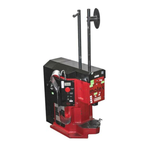
molex VHDCI User manual

VHDCI Terminator Press
Doc. No: ATS-622004500 Release Date: 0 -20-01 UNCONTROLLED COPY Page 1 of 19
Revision: H Revision Date: 09-0 -17
VHDCI TERMINATOR PRESS
Order No. 62200-4500
For Ul ra+™ VHDCI Connec or Series No. 71425
Description
Operation
Maintenance

VHDCI Terminator Press
Doc. No: ATS-622004500 Release Date: 0 -20-01 UNCONTROLLED COPY Page 2 of 19
Revision: H Revision Date: 09-0 -17
Safe y Warnings and Informa ion
Read
and
unders and
all of the instructions and safety
information in this manual before
operating or servicing this tool.
Keep this manual available when using this tool.
Replacement manuals are available for download at no charge at www.molex.com.
SAFETY ALERT SYMBOL
This symbol is used to call your attention to hazards or unsafe practices which could result in an injury
or property damage. The signal word, defined below, indicates the severity of the hazard. The message
after the signal word provides information for preventing or avoiding the hazard.
DANGER
DANGER:
Indicates an imminently hazardous situation which, if not avoided, could result in death or serious injury.
WARNING
WARNING:
Indicates a potentially hazardous situation which, if not avoided, could result in death or serious injury.
CAUTION
CAUTION:
Indicates a potentially hazardous situation which, if not avoided, may result in minor or moderate injury.
CAUTION may also be used to alert against unsafe practices associated with events that could lead
to personal injury.
WARNING
WARNING
Always wear proper eye protection when
Operating or servicing this equipment.
Failure to wear eye protection could result
in serious eye injury from flying debris.
Heavy Objec
To avoid muscle strain or back injury, use lifting
aids and proper lifting techniques when removing
or replacing.
Failure to observe these precautions may result in
injury or property damage.
WARNING
WARNING
Never operate, service, install, or adjust this
machine without proper instruction and without
first reading and understanding the instructions
in this manual and all applicable press and/or
wire processing machine.
manuals.
Do no use
compressed air to clean
this equipment.
The forces created by compressed
air can force debris into the tool.
Failure to observe these precautions may
result in injury or property damage.
WARNING
Never
use this press without guards or safety devices that are intended to prevent hands from
remaining in
the die space.
Failure to observe this warning could result in Severe injury or death.
CAUTION
Never
perform any service or maintenance other than as described in this manual.
Never modify, alter or misuse the equipment
Molex specifications are valid only when used with Molex terminals, applicators and tooling.
Failure to observe this precaution may result in injury and property damage.

VHDCI Terminator Press
Doc. No: ATS-622004500 Release Date: 0 -20-01 UNCONTROLLED COPY Page 3 of 19
Revision: H Revision Date: 09-0 -17
Tooling Technical Assis ance
Molex offers tooling technical assistance for customers who may need some guidance for tooling adjustments.
This support can be obtained by calling either of the two numbers listed below and asking for the Molex Tooling
Group.
Call Toll Free 1- 00-7 6-6539 (US) 1-630-969-4550 (Global).
This assistance is limited to the operation and set-up of a customer’s Molex Press. Questions with regard to
Molex connector products or how to identify the proper tooling and/ or tooling documentation should be directed to
your local Molex personnel or Customer Service Representative.
When calling for service on the press a copy of the Tooling Manual and Specific Applicator Tooling Specification
Sheet should be present and a person that is familiar with the applicator should be present. Be sure the following
information is supplied:
1. Customer name
2. Customer address
3. Person to contact such as (name, title, e-mail, and telephone number
4. Applicator order number (Lease number also if applicable)
5. Serial number (Lease number also if applicable)
6. Molex Connector product order number
7. Urgency of request
. Nature of problem
Molex Applica ion Tooling Group
2200 Wellington Court
Lisle, IL 60532, USA
Tel: +1 (630) 969-4550
Fax:+1 (630) 505-0049
Visit our Web site at http://www.molex.com

VHDCI Terminator Press
Doc. No: ATS-622004500 Release Date: 0 -20-01 UNCONTROLLED COPY Page 4 of 19
Revision: H Revision Date: 09-0 -17
Table of Con en s
Con en s
VHDCI TERMINATOR PRESS ............................................................................................................................................. 1
Order No. 62200-4500 ...................................................................................................................................................... 1
Safe y Warnings and Informa ion ...................................................................................................................................... 2
Section 1 ........................................................................................................................................................................... 5
General Description ...................................................................................................................................................... 5
1.1. Description......................................................................................................................................................... 6
1.2 Features ............................................................................................................................................................ 6
1.3 Technical Specifications .................................................................................................................................... 6
1.4 Delivery Check .................................................................................................................................................. 6
1.5 Tools .................................................................................................................................................................. 6
Section 2 ........................................................................................................................................................................... 7
Installation..................................................................................................................................................................... 7
Principal Mechanical Parts of the 62200-4500 Terminator Press .................................................................................
2.1 Installation ......................................................................................................................................................... 9
2.2 Setup ................................................................................................................................................................. 9
2.3 Operation ........................................................................................................................................................... 9
Section 3 ......................................................................................................................................................................... 12
Maintenance ............................................................................................................................................................... 12
3.1 Maintenance .................................................................................................................................................... 13
3.2 Perishable Parts .............................................................................................................................................. 13
3.3 Spare Parts...................................................................................................................................................... 13
3.4 Preventive Maintenance .................................................................................................................................. 14
3.5 Troubleshooting ............................................................................................................................................... 14
Section 4 ......................................................................................................................................................................... 15
4.1 Parts List ......................................................................................................................................................... 16
4.2 Assembly Drawings (Sheet 1 of 2) .................................................................................................................. 17
4.2 Assembly Drawings (Sheet 2 of 2) .................................................................................................................. 1
Section 5 ......................................................................................................................................................................... 19
Glossary Of Terms ...................................................................................................................................................... 19

VHDCI Terminator Press
Doc. No: ATS-622004500 Release Date: 0 -20-01 UNCONTROLLED COPY Page 5 of 19
Revision: H Revision Date: 09-0 -17
Sec ion 1
General Descrip ion
1.1 Description
1.2 Features
1.3 Technical Specifications
1.4 Delivery Check
1.5 Tools

VHDCI Terminator Press
Doc. No: ATS-622004500 Release Date: 0 -20-01 UNCONTROLLED COPY Page 6 of 19
Revision: H Revision Date: 09-0 -17
1.1. Descrip ion
The Molex 62200-4500 Termination Press was
designed as a stand alone unit. It will terminate the
wires of a multi-conductor cable to the Molex
Ultra+™ VHDCI (Very High Density Cable
Interconnect) connector (71425).
An operator hand loads a housing cover into the
nest assembly. Wires are loaded into the wire cover
grooves. The press ram is lowered to push the wire
into the wire cover and cut off the wires. Then the
plug assembly is placed in the nest and the ram is
brought down again to terminate, completing one
side of the connector. The process is then repeated
for second half of the connector. This press is
ideally suited for low to medium volume, semi-
automatic applications.
1.2 Fea ures
Does all termination steps - No additional tooling
required
Low force required to insert wires and terminate
No air or electricity needed.
1.3 Technical Specifica ions
Dimensions
Length 457.2mm (1 .0in)
Width 203.2mm ( .0in)
Height 355.6mm (14.0in)
Weigh
1 .0kg (40lb)
Ra e
Approximately 6 terminated 6 ct. plugs per hour
depending on the operator skill and speed.
Connec or
Molex Ultra +™ VHDCI 71425-3001
Shielded Plug Assembly 71425-0002
Wire Cover 71424-0001
Cable Type
30AWG:
Round, jacketed, twisted-pair cable conforming to
the ANSI SCSI specifications; 6 conductors;
30AWG, stranded or solid, with .5 /.66mm
insulation O.D.
2 AWG (Optional):
Round, jacketed, twisted-pair cable conforming to
the ANSI SCSI specifications; 6 conductors;
2 AWG, stranded or solid, .71/.76mm (.02 /.030
in.) insulation O.D. See Terminating 28 AWG Wire,
Section 2.2 for details.
1.4 Delivery Check
Carefully remove the machine from its shipping
container and check to determine if the following
articles are included in the package.
Order No. Description Quantity
62200-4500 VHDCI Terminator 1
ATS-622004500 Instruction Manual 1
1.5 Tools
The following tools may be needed to operate and
adjust this tooling:
Metric Hex Wrench Set
Inch Hex Wrench Set
5X Eye Loupe
Needle Nose Pliers

VHDCI Terminator Press
Doc. No: ATS-622004500 Release Date: 0 -20-01 UNCONTROLLED COPY Page 7 of 19
Revision: H Revision Date: 09-0 -17
Sec ion 2
Ins alla ion
2.1 Installation
2.2 Set-Up
2.3 Operation

VHDCI Terminator Press
Doc. No: ATS-622004500 Release Date: 0 -20-01 UNCONTROLLED COPY Page of 19
Revision: H Revision Date: 09-0 -17
Principal Mechanical Par s of he 62200-4500 Termina or Press
Figure 2-1
RAM
LEVER
NEST SPRING PAD
AND WIRE COMB
PRESS
DETENT STOP
TOP SLIDE SHOWN IN
THE OUT POSITION
WIRE RETAINER
HOOK
PLUG
COVER NEST
BOTTOM SLIDE SHOWN
IN THE OUT POSITION
PLUG
RETAINER
CABLE
NEST
AND CLAMPS
WIRE COMB
CUT
-
OFF B
LA
DE
AND STRIPPER
TERMINATION
BLADE
ADJUSTABLE
DOWN STOP

VHDCI Terminator Press
Doc. No: ATS-622004500 Release Date: 0 -20-01 UNCONTROLLED COPY Page 9 of 19
Revision: H Revision Date: 09-0 -17
WIRE GROOVE
Figure 2-3
SET SCREWS
ADJUSTABLE
DOWN STOP
Figure 2-2
2.1 Ins alla ion
Place termination press on a solid level surface
with enough space around it to allow for operation
and easy loading of connectors.
Holes are provided for 1/4in lag bolts to secure the
press to work surface if desired.
Make sure there is adequate lighting and enough
room around the press to allow easy access to the
press and easy handling of cables and connectors.
2.2 Se up
Termina ion Dep h Adjus men
The termination depth can be changed by adjusting
the set screws on the Adjustable Down Stop.
Turning them clockwise (CW) reduces termination
depth, while turning them counter-clockwise (CCW)
increases the termination depth. See Figure 2-2.
Die blocks should be used to set tool closure height
at 4.61 ± 0.12mm (.1 2±.005)
Termina ing 28 AWG Wire
The Termination Press is furnished with the 30 AWG
wire comb and nest spring pad installed.
Terminators using 2 AWG wire require wire comb
order no. 62200-4510 and nest spring pad order
no.62200-4507.
To change the wire comb and nest spring pad follow
the steps below: (see Sheet 2 of the Assembly
Drawing.)
1. Remove the (2) #10 screws from the front of the
lower slide and pull the lower tooling out of the
slide.
2. Turn the lower tooling over. Remove the (4) #
screws located in the middle of the tooling using
a 9/64” hex key.
3. Remove the nest assembly Item numbers (6, 7,
, and 9) from the lower tooling,
4. Remove the (2) # BHCS holding the combs
(Item 6).
5. Install the appropriate nest spring pad (Item 7)
and springs.
6. Install the appropriate wire comb (Item 6) to the
left and right locators (Item and 9).
7. Install the nest assembly on the lower tooling.
. Put the lower tooling back in its slide.
9. Install the (2) #10 screws in the front of the lower
slides.
2.3 Opera ion
Firs Side Termina ion
1. Pull the bottom slide out to access the nest.
2. Load the Wire Cover into the Nest with the wire
cover grooves facing up. See Figure 2-3.
3. Place the cable into the Nest and press into the
clamp making sure the cable is against the
Cable Jacket Stop.
4. Fold the wires under the Wire Retainer Hook to
keep wires clear while loading the nest. See
Figure 2-4.
VHDCI Terminator Press
Doc. No: ATS-622004500 Release Date: 0 -20-01 UNCONTROLLED COPY Page 10 of 19
Revision: H Revision Date: 09-0 -17
Figure 2-4
NEST SPRING PAD
AND WIRE COMB
WIRE RETAINER
HOOK
PLUG NEST
PLUG
RETAINER
CABLE
NEST
AND CLAMPS
WIRE COMB
CABLE
WIRE
COVER
WIRES
WIRE
COVER
Figure 2-6
PLUG
ASSEMBLY
PRESS DETENT
STOP IN THE
“IN” POSITION
Figure 2
-
5
DETENT
PIN
IN THIS POSITION
DETENT PIN
IN THIS POSITION
PRESS DETENT
STOP IN THE
“OUT” POSITION
5. String the first 34 wires through the Wire Comb
and into the Nest Spring Pad Comb making sure
they are positioned in the appropriate circuit
locations.
6. Rotate the Press Detent Stop to the "OUT"
position. See Figure 2-5. (The groove in the
stop must be in-line with the stop screw in the
press ram.)
7. Push the Bottom Slide in.
. Push the Top Slide in.
9. Lower the Press Ram to insert the wires into the
wire cover and cut them to the proper length.
Return the Press Ram to full up position.
10. The Press Detent Stop should remain in the
"OUT" position. See Figure 2-5.
11. Pull Bottom Slide out.
12. Load the plug into the Plug Nest making sure
the appropriate side of the plug is facing down.
See Figure 2-6.
13. Push the Bottom Slide in.
14. Pull the Top Slide out.
15. Lower the Press Ram to complete first side
termination. Return the Press Ram to the full up
position.
No e: For the first termination the Press Detent
Stop must be in the OUT position before the
ram is lowered. See Figure 2-5.
16. Push the Top Slide in.
17. Pull the Bottom Slide out.
Second Side Termina ion
1. Remove the cable assembly. Turn it over and
reload it into the Cable Nest and the Cable
Clamps making certain the cable is against the
Cable Jacket Stop.
2. Fold the plug backwards and rotate the Plug
Retainer over the plug to keep it clear while
loading wires.
3. Place the remaining 34 wires under the Wire
Retainer Hook to keep wires clear while loading
wires.
4. Load the second wire cover into the Nest with
wire cover grooves facing up.
5. String the remaining 34 wires through the Wire
Comb and into the Nest Spring Pad Comb
making sure the wires are positioned in the
appropriate circuit locations.

VHDCI Terminator Press
Doc. No: ATS-622004500 Release Date: 0 -20-01 UNCONTROLLED COPY Page 11 of 19
Revision: H Revision Date: 09-0 -17
6. Make sure the Press Detent Stop is OUT.
7. Push the Bottom Slide in.
. Lower the Press Ram down to insert the wires
into the wire cover then cut them to the proper
length. Return the Press Ram to the up
position.
9. Rotate the Press Detent Stop to the IN position
(the raised area of the stop must be under the
stop screw in the press ram). See Figure 2-5.
NOTE: The Press Detent Stop must be at the IN
position for the second side termination.
10. Pull the Bottom Slide out.
11. Rotate the Plug Retainer to free the plug and
then fold it forward and load it into the Plug
Nest.
12. Push the Bottom Slide in.
13. Pull the Top Slide out.
14. Lower the Press Ram until it stops against the
Press Detent Stop to complete second side
termination. Return the Press Ram to full up
position.
NOTE: The Press Detent Stop must be at the
IN position before lowering the ram. See
Figure 2-5.
15. Push the Top Slide in.
16. Pull the Bottom Slide out.
17. Remove the completed cable assembly.

VHDCI Terminator Press
Doc. No: ATS-622004500 Release Date: 0 -20-01 UNCONTROLLED COPY Page 12 of 19
Revision: H Revision Date: 09-0 -17
Sec ion 3
Main enance
3.1. Maintenance
3.2. Perishable Parts
3.3. Spare parts
3.4. Preventive Maintenance
3.5. Troubleshooting
3.6. Fault Messages

VHDCI Terminator Press
Doc. No: ATS-622004500 Release Date: 0 -20-01 UNCONTROLLED COPY Page 13 of 19
Revision: H Revision Date: 09-0 -17
3.1 Main enance
Cleaning
See Chart for recommended Preventive Maintenance Schedule
For efficient operation, the VHDCI Terminator Press should be cleaned daily with a soft brush to remove any debris
and plating dust from the tooling area. For continuous operation this may need to be done several times a day.
CAUTION: Using compressed air to clean tooling is not recommended. Chips can wedge in the tooling and/or fly
at an operator.
When it is necessary to change tooling, care should be taken to remove any debris from the tapped holes or the
mounting surfaces. Debris can prevent the tooling from being properly locked into position.
Lubrica ion
Sparingly lubricate the sliding parts approximately every month with a synthetic based lubricant with Teflon such as
Permatix "SUPERLUBE".
3.2 Perishable Par s
Perishable parts are parts that contact the connector and can wear over time. The customer is responsible for
maintaining these parts and Molex recommends that they keep at least one set on hand at all times. The
perishable parts are identified in the Parts List in Section 4.
3.3 Spare Par s
Spare Parts are parts that are available to support the VHDCI terminator press in service. They are moving or
otherwise functioning parts that could be damaged or malfunction. It is suggested that the customer may want to
keep some or all of them on hand to reduce down time. These parts are identified in the Parts List in Section 4

VHDCI Terminator Press
Doc. No: ATS-622004500 Release Date: 0 -20-01 UNCONTROLLED COPY Page 14 of 19
Revision: H Revision Date: 09-0 -17
3.4 Preven ive Main enance
DAILY: Clean, See Sec ion 3.1
MONTHLY: Lubrica e, See Sec ion 3.2
CHECK SHEET MONTH YEAR
Week Daily Use
Days of he Week
Solu ion
MON
TUE
WED
THU
FRI
SAT
SUN
1
2
3
4
Cleaning
Daily
Lubricate
Monthly
Schedule should be adjusted up or down depending on usage. Molex recommends that a log of preventive
maintenance be kept with the tool.
3.5 Troubleshoo ing
Symp om
Cause
Solu ion
Wires cut by the
IDT terminal
More than one wire per groove
.
Re
p
lace wires
Termination set too deep.
Adjust termination depth
.
See Section 2.2.
Press down stop not in.
Rotate
the
Press Down Stop
to the in position.
Poor wire retention
Wrong wire size
.
Check product specifications
.
Wrong cable position
More than one wire per
groove or groove missed. Replace wires.
Does not cut wires
or poor quality cut
Dull cutting edge.
Sharpen or replace cut
-
off .blade.
Termination depth not
set properly.
Adjust termination depth
See Section 2.2.
Wrong tooling position.
Review operating instruc
tions.
Termination
Backwards Plug put in backwards. Review operating instructions.
Covers not seated Termination set too shallow.
Adjust termination depth.
See Section 2.2.
Damaged plug
Wrong tooling.
Review operator's manual.
Tooling hits.
Check alig
nment.
Plug jammed in nest.
Remove and scrap and
check for debris

VHDCI Terminator Press
Doc. No: ATS-622004500 Release Date: 0 -20-01 UNCONTROLLED COPY Page 15 of 19
Revision: H Revision Date: 09-0 -17
Sec ion 4
4.1 Parts Lists
4.2 Assembly Drawings

VHDCI Terminator Press
Doc. No: ATS-622004500 Release Date: 0 -20-01 UNCONTROLLED COPY Page 16 of 19
Revision: H Revision Date: 09-0 -17
4.1 Par s Lis
62
2
00
-
4
5
00 VHDCI Termina or
Press
Figure
4
-
1
and 4
-
2
I em
Order No
Descrip ion
RSP
/
PP
Par s
Quan i y
1
11
-
21
-
6 59
Top Clamp Spring
RSP
4
2
62200
-
4503
Top Die Plate (Modified)
1
3
62200
-
4504
Bottom Die Plate (Modified)
1
4
62200
-
4507
Nest Spring Pad (2 AWG)
PP
1
5
62200
-
4510
Wire Comb (2 AWG)
PP
1
6
62200
-
4511
Wire Comb (30 AWG)
PP
1
7
62200
-
4513
Nest Spring
Pad (30 AWG)
PP
1
62200
-
4514
Left Housing Locator
1
9
62200
-
4515
Right Housing Locator
1
10
62200
-
4516
Pilot Locator
2
11
62200
-
4519
Top Clamp
1
12
62200
-
4520
Cut
-
Off Blade
PP
1
13
62200
-
4521
Stripper
1
14
62200
-
4522
Stripper Mount
1
15
62200
-
4523
Stripp
er Slide
1
16
62200
-
4524
Termination Blade
PP
1
17
62200
-
4525
Slide Cover Stripper
1
1
62200
-
4526
Top Tooling Slide
1
19
62200
-
4527
Top Slide Rails
2
20
62200
-
4530
Platen
2
21
62200
-
4531
Lower Tooling Slide
1
22
62200
-
4532
Lower Slide Cover
2
23
62200
-
4533
Handle Mount Platen
1
24
62200
-
4537
Cable Nest
1
25
62200
-
453
Cable Clamp (Modified)
2
26
62200
-
4541
Ram Return Spring Spacer
2
27
62200
-
45
53
Detent Stop
1
2
62200
-
4547
Wire Retainer Hook
1
29
62200
-
454
Plug Retainer
1
30
62200
-
4551
Cut
-
off Die and Nes
t
1
31
63600
-
04 2
Ball Detent
4
32
63700
-
0 69
Press
1
33
63700
-
0 70
Nest Spring
RSP
2
34
63700
-
0 71
Handle
2
35
63700
-
0 72
Ram Spring Return
RSP
2
36
63700
-
0 74
Ball Plunger
2
37
63700
-
0 75
Stripper Spring
RSP
2
3
63700
-
0 76
Adjustable Down Stop
1
39
63700
-
0
77
Up Stroke Limiter
1
40
63700
-
1042
Wire Retainer Hook Spring
RSP
1
41
N/A
1/
by 5/ in.
Diameter Dowel
1
**
42
N/A
.312 Diameter Dowel
4**
43
63700
-
4629
Shoulder Screw
1**
RSP
-
Part
is
a Molex
R
ecommended
S
pare
P
art
.
PP
-
P
art
is
a
P
erishable
P
art
.
** Available from an industrial supply company such as MSC (1
-
00
-
645
-
7270).

VHDCI Terminator Press
Doc. No: ATS-622004500 Release Date: 0 -20-01 UNCONTROLLED COPY Page 17 of 19
Revision: H Revision Date: 09-0 -17
18
27
39
32
34
16
(4)
2
4
1
(4)
1
19
42
(2)
36
3
8
37
(2)
Figure 4
-
1
Shee 1 of 2
See Figure 4-2
17
13
14
11
12
15
4.2 Assembly Drawings (Shee 1 of 2)

VHDCI Terminator Press
Doc. No: ATS-622004500 Release Date: 0 -20-01 UNCONTROLLED COPY Page 1 of 19
Revision: H Revision Date: 09-0 -17
Figure 4
-
2
Shee 2 of 2
10
9
28
31
7
24
29
35
23
30
3
4
0
20
33
6
22
(4)
26
32
25
36
3
4
See Figure 4
-
1
21
4
3
8
(2)
(2)
(REF)
(2)
4
5
(28 AWG)
or
(30 AWG)
(28 AWG)
or
(30 AWG)
(2)
(2)
(2)
4.2 Assembly Drawings (Shee 2 of 2)

VHDCI Terminator Press
Doc. No: ATS-622004500 Release Date: 0 -20-01 UNCONTROLLED COPY Page 19 of 19
Revision: H Revision Date: 09-0 -17
Sec ion 5
Glossary Of Terms
Termina ion Device at the end of a transmission line that completes a circuit.
Plug Assembly An electrical connector intended to be attached to the free end of a conductor, wire, cable or
bundle, which couples or mates to a receptacle connector.
ULTRA+™ Molex trademark for VHDCI connector.
VHDCI Very High Density Cable Interconnect
Wire Cover The part of a VHDCI connector that the wires are pressed into for alignment purposes
prior to be terminated. The covers serve to protect the terminations.
Con ac Informa ion
For more information on Molex application tooling please contact Molex at 1- 00-7 6-6539.
Visit our Web site at http://www.molex.com
This manual suits for next models
1
Table of contents
Other molex Power Tools manuals

molex
molex RAST 5.0 Arbor Press Terminator User manual

molex
molex 63823-5700 User manual

molex
molex TM-3000 User manual

molex
molex Mini Mi2 User manual

molex
molex 63816-0100 Manual

molex
molex 63811-7500 User manual

molex
molex 63801-8550 User manual

molex
molex TM2000 User manual

molex
molex 63811-0300 User manual

molex
molex Mini Mi2 User manual

molex
molex 63827-8800 User manual

molex
molex 19286-1000 User manual

molex
molex 11-31-6356 User manual

molex
molex 69020-0660 User manual

molex
molex 63819-7300 User manual

molex
molex TM-3000 User manual

molex
molex 69020-2025 User manual

molex
molex TM-3000 User manual

molex
molex 64000-0041 User manual

molex
molex 63827-2000 User manual