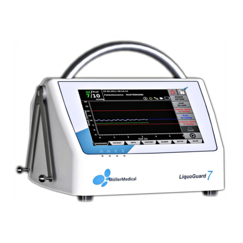
Moller Medical LiquoGuard 7 User manual

CSF drainage pump
Instruction Manual
en
7

IMPORTANT
READ CAREFULLY BEFORE USE
KEEP THESE INSTRUCTIONS FOR FUTURE CONSULTATION
© Möller Medical GmbH
All rights reserved.
No parts of this document may be reproduced or translated in any form or by any means without the prior
written permission of Möller Medical GmbH. The latest version of the information, specifications and
illustrations provided in this instruction manual is indicated by the version number on the last page. Möller
Medical GmbH reserves the right to make changes to technology, functions, specifications, design and
information at any time and without prior notification.

Table of contents
Page 3 of 136
Table of contents
1General safety instructions.......................................................................... 9
1.1 Explanation of the safety symbols used .......................................................... 9
1.1.1 Symbols used in instruction manual.................................................... 9
1.1.2 Symbols appearing on the device ....................................................... 9
1.1.3 Symbols appearing on the LiquoGuard®7 display ............................. 10
1.1.4 Symbols indicated on the retail packaging ........................................ 12
1.2 Explanation of the conventions applied......................................................... 14
1.3 Manufacturer’s responsibility......................................................................... 14
1.4 Equipotential bonding.................................................................................... 14
1.5 Owner´s duty of care..................................................................................... 15
1.6 Additional accessories .................................................................................. 16
1.7 Single use..................................................................................................... 16
1.8 Declaration on DEHP.................................................................................... 17
1.9 Application during defibrillation and for electrosurgical devices..................... 17
2Purpose ....................................................................................................... 18
2.1 Indications of temporary intrathecal CSF drainage........................................ 18
2.2 Indications for permanent CSF drainage....................................................... 19
2.3 Contraindications.......................................................................................... 19
2.4 Complications ............................................................................................... 19
2.5 Combination with other products, catheters and cannulas ............................ 20
2.6 Patient population & residual risk.................................................................. 21
2.7 Essential performance .................................................................................. 21
3Product description.................................................................................... 22
3.1 Touchscreen................................................................................................. 23
3.2 Bag holder .................................................................................................... 23
3.3 Universal bracket.......................................................................................... 23
3.4 Pump............................................................................................................ 23
3.5 LEDs............................................................................................................. 23
3.6 Connection options....................................................................................... 24
3.7 User interface ............................................................................................... 25
3.7.1 Tab bar............................................................................................. 26
3.7.2 Softkeys............................................................................................ 27
3.7.3 Keyboard screen............................................................................... 27
3.8 Diagram dialog field ...................................................................................... 29
3.8.1 Diagram............................................................................................ 30
3.8.2 Info bar ............................................................................................. 32
General safety instructions
Page 4 of 136
3.8.3 Softkeys............................................................................................ 33
4Installation and startup............................................................................... 37
4.1 Transport and storage instructions................................................................ 37
4.2 Unpacking the device and inspecting delivery............................................... 37
4.3 Operating the LiquoGuard®7......................................................................... 37
4.3.1 Hanging onto a standard rail............................................................. 38
4.3.2 Installation on an infusion stand........................................................ 38
4.3.3 Connecting and turning the device on............................................... 39
4.4 Suitable operating environment..................................................................... 40
5Application and Operation ......................................................................... 41
5.1 Installation and startup.................................................................................. 41
5.2 Switching on the LiquoGuard®7..................................................................... 41
5.3 Preparing the tubing set................................................................................ 42
5.4 Connecting the sensor cable......................................................................... 42
5.5 Inserting the tube.......................................................................................... 42
5.6 Connecting the catheter................................................................................ 43
5.7 Pressure sensor housing –Positioning and fastening................................... 44
5.8 Changing drainage settings........................................................................... 46
5.8.1 Pressure controlled drainage ............................................................ 46
5.8.2 Volume controlled drainage .............................................................. 47
5.9 Starting the application.................................................................................. 47
5.10 Pausing the application, only pressure monitoring ........................................ 47
5.11 Interrupting the application............................................................................ 48
5.12 Changing the drainage set............................................................................ 49
5.13 Displaying drainage information.................................................................... 49
5.13.1 Alarms .............................................................................................. 49
5.13.2 Battery.............................................................................................. 49
5.14 Turning off the device.................................................................................... 49
5.15 Storage......................................................................................................... 50
6Settings........................................................................................................ 51
6.1 Drainage....................................................................................................... 51
6.1.1 Pset (set pressure value).................................................................. 51
6.1.2 Upper Alarm...................................................................................... 52
6.1.3 Lower Alarm...................................................................................... 52
6.1.4 Vset .................................................................................................. 53
6.2 Alarm............................................................................................................ 54

Table of contents
Page 5 of 136
6.2.1 General............................................................................................. 54
6.2.2 Flow.................................................................................................. 55
6.2.3 Pulsation........................................................................................... 57
6.2.4 Parenchymal/Tip sensor ................................................................... 59
6.2.5 Monitor/Nurse Call............................................................................ 59
6.2.6 CPP/cMAP Sensor............................................................................ 59
6.3 Setup............................................................................................................ 59
6.3.1 Language.......................................................................................... 59
6.3.2 Display.............................................................................................. 60
6.3.3 Config............................................................................................... 62
6.3.4 Operation.......................................................................................... 64
6.3.5 Service.............................................................................................. 65
6.3.6 Presettings........................................................................................ 68
7Alarm signals and corrective measures.................................................... 69
7.1 Presence of an alarm condition..................................................................... 69
7.1.1 Technical and physiological alarm conditions.................................... 69
7.1.2 Pause alarm signal ........................................................................... 70
7.1.3 System error..................................................................................... 71
7.2 Testing alarm functions................................................................................. 72
7.3 Alarm system, dual safety............................................................................. 72
7.4 Alarm system overview................................................................................. 73
7.5 Alarm system description.............................................................................. 80
7.6 Troubleshooting............................................................................................ 83
7.7 Service.......................................................................................................... 84
8Care.............................................................................................................. 86
8.1 Cleaning and disinfection.............................................................................. 86
8.2 Service.......................................................................................................... 87
8.3 Replacing the battery.................................................................................... 87
8.4 Disposal........................................................................................................ 87
9Device options ............................................................................................ 88
9.1 Monitor/Nurse call......................................................................................... 89
9.1.1 Patient monitor system...................................................................... 89
9.1.2 Nurse call system.............................................................................. 90
9.2 Documentation.............................................................................................. 91
9.2.1 Patient data....................................................................................... 91

General safety instructions
Page 6 of 136
9.2.2 Application data................................................................................ 92
9.2.3 Set marker........................................................................................ 94
9.2.4 History .............................................................................................. 95
9.2.5 Printing ............................................................................................. 97
9.3 Presettings.................................................................................................... 99
9.3.1 Editing the LiquoGuard®7 presettings ............................................... 99
9.3.2 Copy drainage settings to tubing set............................................... 101
9.4 Printing ....................................................................................................... 101
9.5 Parenchymal/Tip sensor ............................................................................. 102
9.5.1 Connecting the Parenchymal/Tip senor .......................................... 103
9.5.2 Settings........................................................................................... 104
9.6 CPP/cMAP.................................................................................................. 107
9.6.1 Basic principles............................................................................... 107
9.6.2 Positioning the MAP sensor............................................................ 107
9.6.3 Connecting the MAP sensor ........................................................... 108
9.6.4 cMap sensor settings...................................................................... 108
9.7 Lumbar infusion test.................................................................................... 109
9.7.1 General description......................................................................... 109
9.7.2 Indications....................................................................................... 111
9.7.3 Contraindications............................................................................ 111
9.7.4 Complications................................................................................. 111
9.7.5 Combination with other products..................................................... 112
9.7.6 Patient population........................................................................... 112
9.7.7 Residual risk................................................................................... 112
9.7.8 Execution of the lumbar infusion test............................................... 112
9.7.9 Application and operation................................................................ 113
9.7.10 Settings........................................................................................... 116
9.7.11 Alarms ............................................................................................ 118
10 Appendix ................................................................................................... 119
10.1 Technical data............................................................................................. 119
10.2 Electromagnetic emission ........................................................................... 122
10.3 Electromagnetic resistance......................................................................... 123
10.4 Recommended safety distances................................................................. 125
10.5 Use in a CT and MRI environment.............................................................. 126
10.5.1 Important safety instructions ........................................................... 126
10.5.2 Measures to avoid image artifacts in MRI ....................................... 127

Table of contents
Page 7 of 136
10.5.3 After MRI imaging........................................................................... 128
10.6 Accessories ................................................................................................ 129
Index ................................................................................................................... 134

Page 8 of 136

General safety instructions
Page 9 of 136
1 General safety instructions
1.1 Explanation of the safety symbols used
In this instruction manual, visual symbols are usedto highlight important instructions . These
references are prerequisites for preventing hazards to patients and operating personnel, as
well for avoiding damages or malfunctioning of the device.
1.1.1 Symbols used in instruction manual
Caution
Information or help
1.1.2 Symbols appearing on the device
Type BF applied part
Defibrillation-proof type CF applied part
Serial number (the 4 digits indicate the ear and month of
manufacture in YYMM format)
Consult instructions for use
Follow instructions for use
Complies with ANSI/AAMI ES 60601-1
CAN/CSA 22.2 No. 60601-1-08
Alternating current
Return and disposal according to WEEE Directive
Main alarm
Backup alarm
Main battery

General safety instructions
Page 10 of 136
Backup battery
ICP
Parenchymal or tip sensor connection (compatiple with Philips
M1006B invasive pressure module connection).
Patient monitor output (compatible with Edwards TruWave)
“ON” for a part of equipment
“OFF” for a part of equipment
Pcsf
Tubing set connection
In/Out
Connection for I/O connector
Only the LiquoGuard®7Multi-Hub accessory may be
attached to this connection!
USB host
RJ45 network connection
Connection to the nurse call system
The BF application parts (Pcsf and ICP) are specified as an application part.
1.1.3 Symbols appearing on the LiquoGuard®7 display
Pump is in Pause mode
Pump is in Application running mode
All alarms are displayed and emitted
10:00
One or more alarms have been actively paused by the
operator. Alarms are not emitted. The remaining time until the
alarms are displayed again is shown.
off
Drainage quantity counter off

General safety instructions
Page 11 of 136
Drainage quantity counter active. Message when the set
drainage quantity is reached.
All physiological alarms displayed and emitted.
5:00
All physiological alarms are suppressed, with the remaining
time displayed until the alarm sounds again
Keypad lock inactive
Keypad lock active
Main battery charge
Presentation mode ready
Softkey: press or save a screenshot
Info bar: Printer is connected
Set a marker for documenting events
One or two USB memory sticks are connected
Presetting is active (instead of X, the number of the presetting
is indicated)
LiquoGuard®7connected to main power supply
;
Scale in/out of the time axis in HISTORY dialog field
Selection of curves to be displayed
Scaling of the axes to optimum
Scaling the axes to maximum
Clear history (graph, volume, alarms, patient data)
;
Move back and forth on the time axis in the History dialog field

General safety instructions
Page 12 of 136
1.1.4 Symbols indicated on the retail packaging
Consult instructions for use
Catalog number
Batch code
Serial number (the 4 digits indicate the ear and month of
manufacture in YYMM format)
Use by date
YYYY-MM-DD
Sterilized using ethylene oxide
Not suitable for use with MRI
Limited suitability of tubing set for use with MRI. See details
under symbol for the condition.
Do not reuse
Do not resterilize
Do not use if package is damaged
Stacking restriction, stack may consists of max. 4 packages
Keep dry
Humidity, limitation
Temperature limit
Manufacturer

General safety instructions
Page 13 of 136
Date of manufacture
YYYY-MM-DD
Total length
Blood pressure, invasive measurement
Follow the instructions for use
Quantity
Type BF applied part
Keep away from sunlight
Caution! Observe transport and storage conditions.
Attention:
Under US Federal law, this device may be sold only to a
physician or ordered by a physician.
For further information about symbols used please refer to our homepage:
www.moeller-medical.com/glossary-symbols.
The use of the LiquoGuard®7CSF drainage pump is subject to thorough knowledge and
observance of this instruction manual which is an integral part of the delivered product.
Store this instruction manual carefully. The present instructions are not a substitute for
training of the owner/operator by a medical device consultant approved by the
manufacturer. The device must be used only by persons who have the required training or
knowledge and experience.
If components are used that do not correspond to the original equipment
manufacturer parts, the performance, safety and EMC behaviour may be
impaired.

General safety instructions
Page 14 of 136
1.2 Explanation of the conventions applied
Various typefaces are used in these instructions for easier reference.
Typeface
Application
Bold and italics
Buttons used in operating procedures
SMALL CAPITALS
Dialog fields and submenus in running text.
Italics
Device options, buttons and references to
chapters and sections in running text.
1.3 Manufacturer’s responsibility
The manufacturer is responsible for the safety, reliability and serviceability of the device in
the following cases:
Where assembly, upgrades, adjustments, changes or repairs are performed only by
persons authorized by the manufacturer.
Where the electrical installation of the area used for medical purposes complies with
the applicable requirements and regulations (e.g. VDE 0100, VDE 0107 or IEC
specifications).
Where the device is used in accordance with the user manual.
Where the regulations specific to a region or country are observed.
The manufacturer undertakes to accept returned old devices according to the Electronic
Equipment Act.
1.4 Equipotential bonding
It is important to limit potential variances between the different parts of a system within the
patient's environment. In limiting this potential variance by using a system of protective earth
conductors, the quality of the connection is of utmost importance. It is, therefore, essential
to avoid a failure in the protective devices in each part of the system.
In the case of failure of the protective earth conductors of a device, a
potential variance can occur at the housing of the device and present a
danger for the operator and the patient. Do not touch the patient and the
device simultaneously.

General safety instructions
Page 15 of 136
1.5 Owner´s duty of care
The owner of the device must accept responsibility for the proper operation of the medical
device. The user is obliged to fulfill all duties in accordance with the regulatory requirements
and is fully responsible for all activities when using medical devices. Only qualified
personnel may operate the LiquoGuard®7. This instruction manual does not replace
training of the user by the medical device consultant. The training is carried out when the
product is delivered by a medical device consultant authorized by the manufacturer with the
aid of all products necessary for use. The operator must ensure that staff are trained on a
regular basis by a qualified person (ideally a medical device consultant authorized by the
manufacturer) if the safe use of the product on the patient cannot be guaranteed due to
inadequate training. Clinical application may be only according to instructions of qualified
personnel.
Any modifications to the LiquoGuard®7are prohibited. Liquids must not
penetrate parts of the device which carry electrical voltage.
Ensure that no cleaning spray enters the connector socket.
Before cleaning, unplug the LiquoGuard®7connector plug and turn the
device off.
Do not turn the pump rotor opposite to the flow direction indicated if the tube
is already connected to the pump. This may present a danger to the patient.
To obtain an accurate pressure measurement, do not use any other
accessories except a suitable extension tube with a maximum length of
30 cm, fitted between the catheter and the tubing set.
Never attach filters (e.g. bacteria filter) between the catheter and drainage
bag.
Application on computer tomographs
The tubing set may remain attached to the patient during computer
tomography (CT). The LiquoGuard®7must be disconnected.
Application on magnetic resonance tomographs
The tubing set may remain attached to the patient during MRI imaging
exams. The LiquoGuard®7must be disconnected and must be located
outside the magnetic field (another room, screened).
It is essential to observe the further measures for use in an MRI environment
from page 126 and in the instruction manual of the respective tubing sets.
Use the device only on a mains power supply fitted with a protective earth
conductor. The mains voltage must conform with the indications provided on
the identification plate on the back.
Replace any connecting cable in the case of even minor damage and take
care not to roll over the cables.

General safety instructions
Page 16 of 136
Keep cables away from sources of heat. This is to prevent the insulation from
melting, potentially causing a fire or electrocution.
Do not force the connector plug into the socket.
Do not pull on the cable when removing the plug. If necessary, loosen the
plug interlock to remove it.
Position the LiquoGuard®7so that it can be easily disconnected from the
mains power supply.
Do not subject the LiquoGuard®7to strong heat or fire.
Do not subject the LiquoGuard®7to strong impacts.
If heat, fumes or smoke are emitted from the LiquoGuard®7, disconnect the
mains plug of the device immediately.
Do not extinguish the LiquoGuard®7with water in the event of fire.
Also observe the safety instructions in the instruction manuals of the devices used in
conjunction with the LiquoGuard®7.
Any serious incident that has occurred in relation to the device should be
reported to the manufacturer and the competent authority of the Member
State in which the user and/or patient is established.
1.6 Additional accessories
Additional accessories, which are beyond the scope of delivery of the present device and
are connected to the analog and digital interfaces of the device, must be proven to comply
with the relevant IEC specifications (e.g. IEC 60601 for electrical medical devices).
Furthermore, all configurations must satisfy the current version of the system requirements
according to standard IEC 60601-1. Any operator connecting the additional devices is
responsible for configuring the system and for ensuring that the current version of the
system requirements satisfy standard IEC 60601-1.
1.7 Single use
The re-use of a single-use product presents a potential risk of infection for the patient or
operator. Contaminated products can damage health, and cause illness or even death of
the patient. Cleaning, disinfection and sterilization can adversely affect essential material
properties and product parameters and thus result in product failure.
Dispose of the used single-use product according to your hygiene requirements. To prevent
leakage from the tubing set, ensure that all stopcocks are closed when disposing of the
drainage and infusion set.

General safety instructions
Page 17 of 136
1.8 Declaration on DEHP
The LiquoGuard®7tubing sets do not contain any bis (2-ethylhexyl) phthalate (DEHP).
1.9 Application during defibrillation and for electrosurgical devices
Do not touch the patient, table or instruments during defibrillation. The measurement
accuracy can be impaired during defibrillation. The recovery time of the device is less than
10 seconds. The recovery time has no effect on patient or device safety. During
defibrillation, use only accessories stated in this instruction manual.
When using electrosurgical devices, the LiquoGuard®7, the LiquoGuard®7Multi-Hub and
the transducers used do not include any protective measures against burning.
The LiquoGuard®7 can be used in combination with electrosurgical devices.
Nevertheless, the strong electromagnetic faults which occur in the direct vicinity of electric
motors, power lines, PCs, monitors or other, possibly faulty, electrical devices can, in
individual cases, impair the functionality of the device.
Consider such faults when observing inexplicable phenomena on the device. The proper
operation of the device can be restored as follows:
Position the pressure sensor housing as far away as possible from the electrosurgical
electrodes.
Set up the devices at a safe distance from each other, check their functionality and
test them for plausibility.
Make sure that the laid patient cables do not touch as electromagnetic coupling is
possible during energy input via the electrosurgical device.
Make sure that no cables are in contact with the patient.
Take all the necessary precautions to avoid malfunctioning.
Note the instructions and recommendations from the manufacturer of the
electrosurgical device.

Purpose
Page 18 of 136
2 Purpose
The Möller Medical GmbH LiquoGuard®7 CSF drainage pump is a pressure-controlled
peristaltic pump. The LiquoGuard®7 Drainage Set is a sterile single-use accessory
designed to be used only with the LiquoGuard®7 CSF drainage pump. The LiquoGuard®7
CSF drainage pump with the LiquoGuard®7Drainage Set are specifically designed to
pump CSF from the ventricular system and the lumbar area of the patient on the basis of
CSF pressure, or when the Parenchymal/Tip sensor and a suitable parenchymal sensor is
used, from the ventricular system of the patient on the basis of parenchymal or CSF
pressure. The LiquoGuard®7Drainage Set is compatible with all conventional ventricle
catheters with an internal diameter greater than/equal to 1 mm and length less than/equal
to 350 mm, as well as lumbar drainage catheters with an internal diameter greater
than/equal to 0.7 mm and length less than/equal to 800 mm.
The LiquoGuard®7Infusion Test Set is a sterile single-use accessory and must be used
only in conjunction with the LiquoGuard®7 CSF drainage pump. The LiquoGuard®7CSF
drainage pump, together with the LiquoGuard®7Infusion Test Set and the Lumbar Infusion
Test function, are designed to ensure the flow of up to 100 ml of infusion solution
(physiological saline solution or CSF replacement fluid) at a consistent volume into the
spinal canal, with simultaneous pressure measurement (see page 108).
The LiquoGuard®7may be used only in monitored medical areas in
hospitals.
The purpose of the LiquoGuard®7not to form a diagnosis, but to support in
forming a diagnosis.
2.1 Indications of temporary intrathecal CSF drainage
Generally, the LiquoGuard®7does not change the indication for intrathecal CSF drainage
in any patient, nor does it influence the therapeutic concept, type of treatment, therapy
objectives, or therapy duration.
The most fundamental characteristics of the LiquoGuard®7system are comparable with
those of other CSF drainage systems on the market. Therefore, the listed indications for
CSF drainage must be understood in the broadest sense, without presupposing the use of
the LiquoGuard®7system or any specific comparable CSF drainage system, as these
systems are interchangeable with each other at all times without the need for a change in
therapy or further surgery.
Communicating hydrocephalus
This condition includes all clinical pictures in which CSF production is temporarily in
disproportion to CSF resorption, usually during cerebral hemorrhage (subarachnoid
hemorrhage, intraventricular hemorrhage), encephalitis and cranial-cerebral injuries. In
most cases, the cause is resorption dysfunction by obstruction of the Paccioni granulation.
There is no alternative treatment to intrathecal CSF drainage for these clinical pictures.

Purpose
Page 19 of 136
Non-communicating hydrocephalus
CSF drainage is temporarily impaired by a partial or complete occlusion of the CSF draining
paths. This case can arise with masses (tumors, cysts, hemorrhage, congenital
malformation) near the foramen of Monro, of the 3rd ventricle, the aqueduct, the 4th
ventricle or the foramen of Monro and the foramina of Luschka.
Therapy-resistant cerebral swelling
CSF drainage may be indicated in therapy-resistant cerebral swelling caused, for example,
by cranial-cerebral injury, cerebral hemorrhage or subarachnoid hemorrhage or by cerebral
swelling due to tumors, inflammation or hypoxia, in order to reduce intracranial pressure,
and to bypass trepanation (the removal of a cranial bone).
Forced CSF pressure reduction
In cases of endovascular or open surgical procedures such as in aortic aneurysms, the CSF
pressure is forcibly lowered so as to achieve better arterial perfusion of distal spinal
segments and thus to reduce the risk of paraplegia, for example.
Lumbar CSF drainage and pressure-controlled drainage may be indicated both intra- and
postoperatively.
2.2 Indications for permanent CSF drainage
If permanent CSF drainage is indicated (e.g. in normal-pressure hydrocephalus), temporary
CSF drainage would be indicated only for diagnostic purposes (e.g. b-wave diagnostics),
but not for continuous therapy. This would indicate a CSF shunt system, usually a
ventriculoperitoneal shunt or a ventriculoatrial shunt.
2.3 Contraindications
Absolute contraindications
Coagulation dysfunction
Thrombocythemia
Relative operative contraindications
Superficial or deep infections of skin, bone, meninges, or brain. Especially in infections of
the brain, meninges, or cerebral chambers (encephalitis, meningitis and ventriculitis),
dysfunctional CSF resorption indicates relief, as does simultaneous intake of intrathecal
antibiotics in the case of ventriculitis.
2.4 Complications
Meningitis
Encephalitis
Ventriculitis

Purpose
Page 20 of 136
Myelitis
Nosocomial infection
Cerebral hemorrhage
Epidural hematoma
Spinal cord injury
Nerve injury
Cone and cauda injury
Back pain
Cerebral swelling
Slit ventricles
Overdrainage
Underdrainage
Disconnection
Bent tubes
Interrupted tube flow (bent tube, occluded tube system (blood clots or detritus))
Death
2.5 Combination with other products, catheters and cannulas
The LiquoGuard®7may be used only with the application parts
LiquoGuard®7Drainage Set REF. No.: 00003497 (1600 mm) or REF.
No.: 00003501 (2000 mm), equivalent versions, see Appendix 10.6 or
LiquoGuard®7Infusion Test Set REF. No.: 00003499 (2000 mm) of Möller
Medical GmbH.
The LiquoGuard®7Drainage Set is connected to a surgically implanted
CSF draining catheter and does not come into contact with the body.
The LiquoGuard®7Drainage Set may be connected only to a ventricle
drainage catheter with internal diameter ≥ 1 mm and length ≤ 350 mm or
lumbar drainage catheter with internal diameter ≥ 0.7 mm and length ≤ 800
mm.
The LiquoGuard®7Tubing Set may be used only with the Möller Medical
CSF bag provided.
To make an extension, all the usual extension tubes may be connected to
the LiquoGuard®7Drainage Set that are suitable for arterial pressure
measurement (sufficient rigidity of the tube), not longer than 30 cm, and
have an inner diameter greater than or equal to 2 mm.
Other manuals for LiquoGuard 7
3
Table of contents
Other Moller Medical Medical Equipment manuals

Moller Medical
Moller Medical Vibrasat power User manual

Moller Medical
Moller Medical LiquoGuard 7 User manual

Moller Medical
Moller Medical Liposat power User manual

Moller Medical
Moller Medical Docon7 Multicharger User manual

Moller Medical
Moller Medical LiquoGuard 7 User manual

Moller Medical
Moller Medical Docon SealM User manual

Moller Medical
Moller Medical Docon 7 User manual