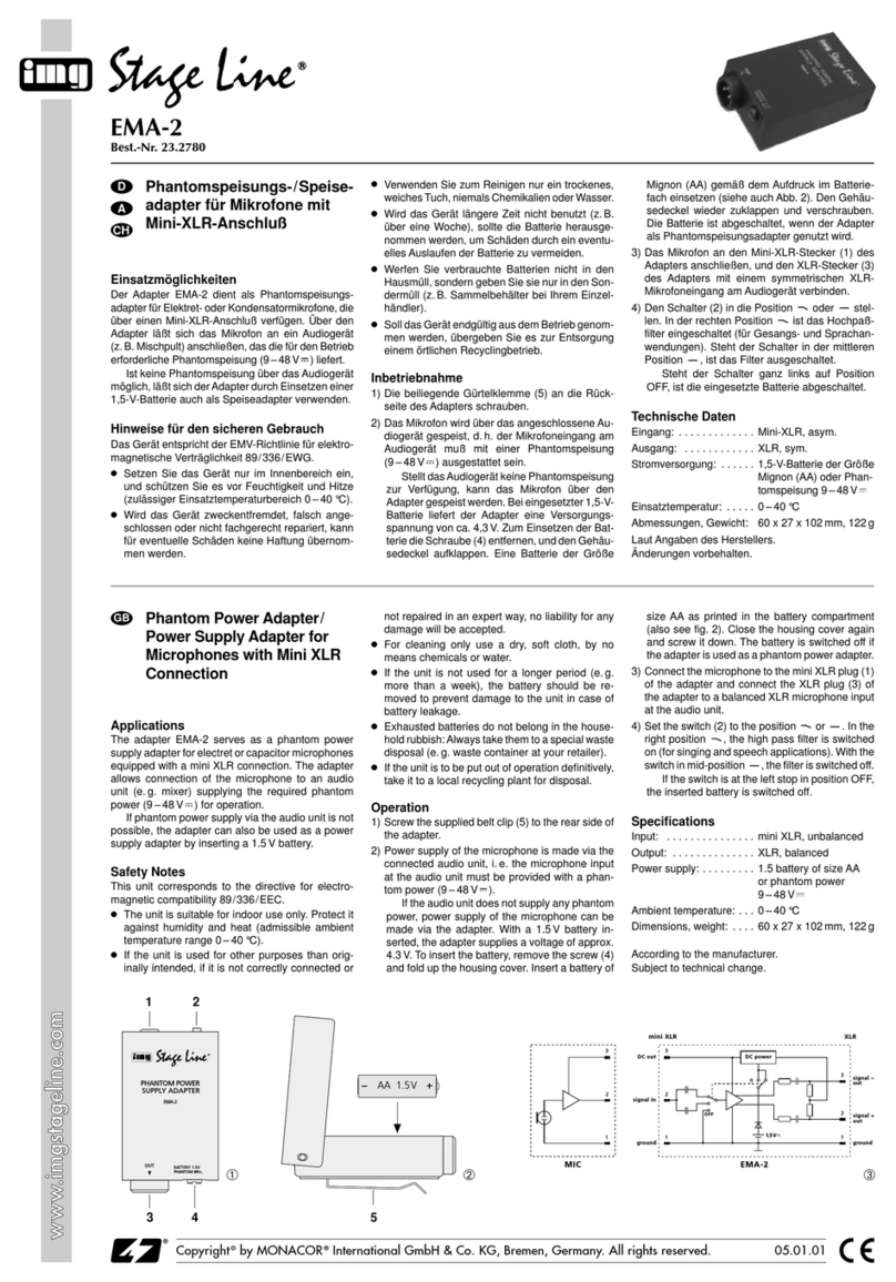
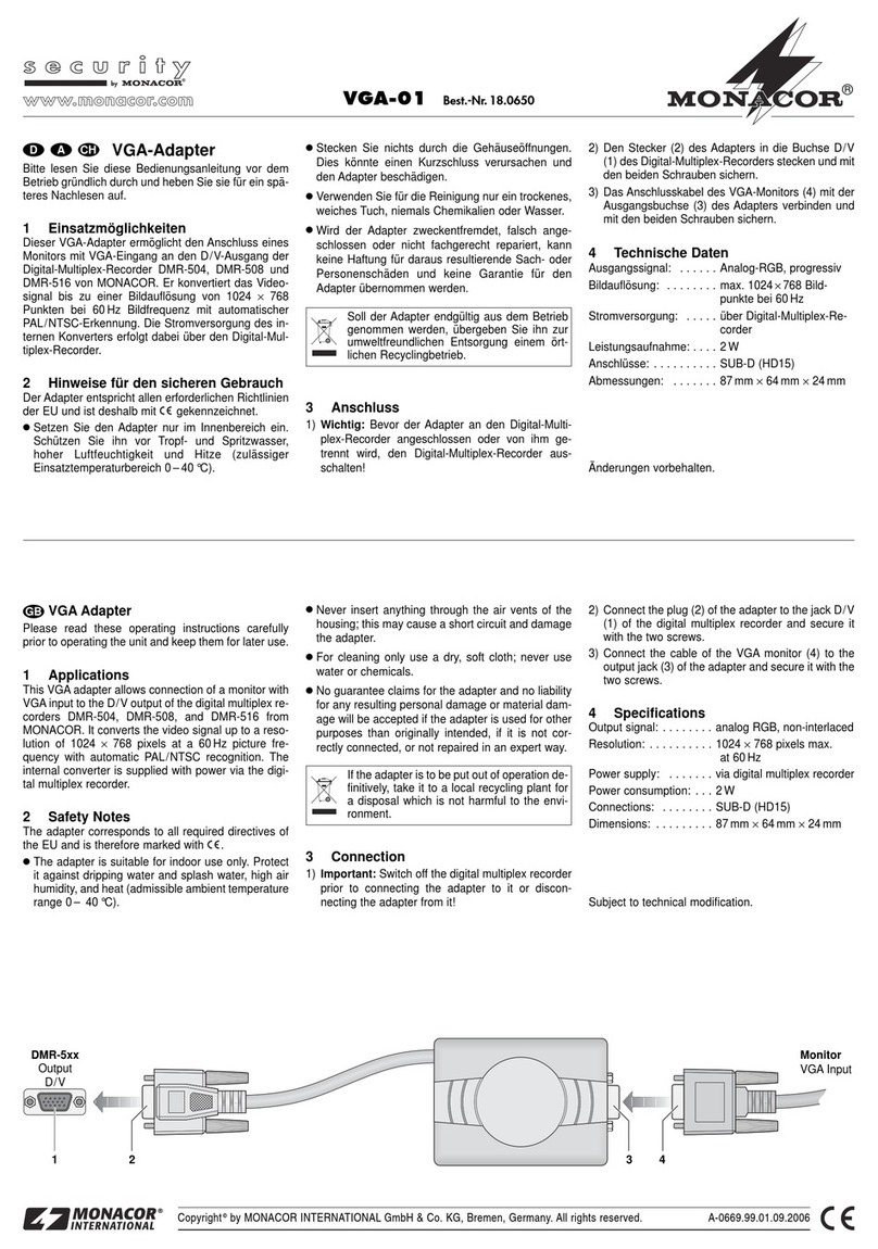
Monacor PATEL-1 User manual

Telefondurchsage-
Adapter für ELA-Anlagen
Bitte lesen Sie diese Anleitung vor der Installation gründlich
durch und heben Sie sie für ein späteres Nachlesen auf.
1 Verwendungsmöglichkeiten
Der Adapter PATEL-1 dient dazu, einen Telefonanruf als
Durchsage über eine ELA-Anlage hören zu können. Er
nimmt den Anruf automatisch an, schaltet die Durch-
sage auf den ELA-Verstärker und beendet nach der
Durchsage den Anruf. Der Adapter wird als analoge
AB-Nebenstelle an eine Telefonzentrale angeschlossen.
2 Bedienelemente und Anschlüsse
Vorderseite
1Gonglautstärke
2Gongtonhöhe und Gongtempo
3DIP-Schalter für Relais, Gong, Durchsageende-Erken-
nung und Durchsage-Zeitbegrenzung (Kap. 5)
4Lautstärke der Durchsage
5Regler für die Besetztzeichenerkennung (Kap. 5.1)
6Anzeige, leuchtet während einer Durchsage
7Betriebsanzeige
Rückseite
8Buchse zum Anschluss des beiliegenden Netzgeräts
9Buchse mit dem Audio- und Relaisausgang zum An-
schluss an einen Eingang der ELA-Anlage über die
beiliegende Anschlussdose (Abb. 3 + 4)
(2-m-Verbindungskabel mit RJ45-Steckern liegt bei)
10 Buchse zum Anschluss an eine Telefondose
(3-m-Verbindungskabel mit TAE-Stecker liegt bei)
3 Hinweise für den sicheren Gebrauch
Die Geräte (Durchsageadapter und Netzgerät) entspre-
chen allen relevanten Richtlinien der EU und sind des-
halb mit gekennzeichnet.
GVerwenden Sie die Geräte nur im Innenbereich.
Schützen Sie sie vor Tropf- und Spritzwasser, hoher
Luftfeuchtigkeit und Hitze (zulässiger Einsatztempe-
raturbereich 0 – 40 °C).
GNehmen Sie den Adapter nicht in Betrieb und ziehen
Sie sofort das Netzgerät aus der Steckdose:
1. wenn sichtbare Schäden am Adapter oder Netzge-
rät vorhanden sind,
2. wenn nach einem Sturz oder Ähnlichem der Ver-
dacht auf einen Defekt besteht,
3. wenn Funktionsstörungen auftreten.
Geben Sie die Geräte in jedem Fall zur Reparatur in
eine Fachwerkstatt.
WARNUNG Das Netzgerät wird mit lebensgefährlicher
Netzspannung versorgt. Nehmen Sie des-
halb nie selbst Eingriffe am Netzgerät vor.
Es besteht die Gefahr eines elektrischen
Schlages.
9V DC PA System Phone Line
1618
89 10
Tone
Chime
Mode Busy Tone
Vol
PWR
ON
OFF 1 2 3 4
PATEL-1
1234567
GVerwenden Sie zum Reinigen nur ein trockenes, wei-
ches Tuch, niemals Chemikalien oder Wasser.
GWerden die Geräte zweckentfremdet, nicht richtig
angeschlossen, falsch bedient oder nicht fachgerecht
repariert, kann keine Haftung für daraus resultierende
Sach- oder Personenschäden und keine Garantie für
die Geräte übernommen werden.
4 Anschluss des Adapters
Alle Anschlüsse sollten nur durch Fachpersonal und unbe-
dingt bei ausgeschalteten Geräten vorgenommen werden!
1) Die Verbindung des PATEL-1 mit einem Line-Pegel-
Eingang der ELA-Anlage erfolgt über die beiliegende
Anschlussdose (Abb. 3 + 4). Die Anschlussdose an
geeigneter Stelle festschrauben. Die Buchse „PA Sys-
tem“ (9) über das beiliegende Kabel mit der Buchse
der Anschlussdose verbinden.
2) Den Audioeingang der ELA-Anlage nach der Abb. 3
anschließen oder, wenn der Audioeingang durch
einen Schalter oder durch ein Relais aktiviert werden
muss, nach der Abb. 4.
Anschlussdose (geöffnet)
zur Verbindung mit der ELA-Anlage
Verbindung zur ELA-Anlage, wenn der Eingang
über ein Relais aktiviert werden muss
3) Zur Verbindung des Adapters mit dem Telefonnetz die
Buchse „Phone Line“ (10) über das beiliegende Kabel
mit dem TAE-Stecker an die Telefondose anschlie-
ßen.
4) Den Kleinspannungsstecker des Netzgerätes in die
Buchse „9 V DC“ (8) stecken und das Netzgerät in
eine Steckdose (230 V~/50 Hz). Die Betriebsanzeige
(7) leuchtet.
5 Grundeinstellungen
1) Die Einstellung der Relaisfunktion und des Gongs
erfolgt mit den DIP-Schaltern „Mode“ (3) Nr. 1 und 2:
1Werkseinstellung
Wenn der Eingang der ELA-Anlage nach der Abb. 3
angeschlossen ist, muss der DIP-Schalter Nr. 1 in
der Position ON stehen.
Nr. Position Funktion
1OFF Relais
schaltet zu Beginn einer Durchsage
kurz um
ON1schaltet während der Durchsage um
2OFF Gong ausgeschaltet
ON1eingeschaltet
1
2
3
4
8
7
6
5
18
zum Audioeingang
der ELA-Anlage
Audio
sym.
zum Sc alteingang
der ELA-Anlage
1
2
3
4
8
7
6
5
18
zum Audioeingang
der ELA-Anlage
Audio
sym.
Sollen die Geräte endgültig aus dem Betrieb
genommen werden, übergeben Sie sie zur
umweltgerechten Entsorgung einem örtlichen
Recyclingbetrieb.
2) Die Durchsageende-Erkennung und die Durchsage-
Zeitbegrenzung werden mit den DIP-Schaltern Nr. 3
und 4 eingestellt:
1Werkseinstellung
2Diese Einstellung nicht verwenden, weil sonst der Anruf nicht
beendet wird.
3) Eine Durchsage ausführen (Kap. 6) und die Laut-
stärke (Ausgangspegel des PATEL-1) mit dem Reg-
ler „Vol“ (4) einstellen.
4) Die Lautstärke des Gongs mit dem Regler
„Chime“ (1) einstellen. Die Gongtonhöhe und das
Gongtempo mit dem Regler „Tone“ (2) einstellen.
5.1 Abgleich der Besetztzeichenerkennung
Dieser Abgleich wurde bereits vom Werk aus durchge-
führt und darf nur geändert werden, wenn der PATEL-1
nach drei Besetztzeichen den Anruf nicht automatisch
beendet (Kap. 6, Bedienschritt 4b).
1) Eine Durchsage nach Kapitel 6 ausführen. Nach der
Durchsage sofort auflegen.
2) Den Regler „Busy Tone“ (5) so einstellen, dass die
LED (6) neben dem Regler im Rhythmus des Be-
setztzeichens aufleuchtet. Wenn die Besetztzeichen-
erkennung korrekt arbeitet, beendet das Gerät den
Anruf automatisch nach 2 – 3 Besetztzeichen.
Hinweis: Das Besetztzeichen der Telefonanlage sollte
dem Standardrhythmus (1⁄2s Ton, 1⁄2s Pause) entspre-
chen. Wenn das Besetztzeichen nicht so eingestellt wer-
den kann, ist eine Anrufbeendigung nur durch das Er-
kennen des Durchsageendes nach 2 s oder 4 s Stille
möglich (Kapitel 6, Punkt 4a).
6 Durchsage ausführen
1) Die Telefonnummer, die dem PATEL-1 zugewiesen
ist, wählen.
2) Sobald die Verbindung aufgebaut ist, den Gong
abwarten [wenn der Gong mit dem DIP-Schalter
„Mode“ Nr. 2 eingeschaltet ist (Position ON)].
3) Die Durchsage sprechen.
4) Um den Anruf zu beenden, gibt es zwei Möglichkeiten:
a) Schweigen, bis das Gerät als erstes den Anruf be-
endet [nach 2 oder 4 Sekunden entsprechend der
Einstellung mit den DIP-Schaltern (3), siehe Kap. 5].
b) Sofort nach der Durchsage auflegen. Das Gerät
erkennt das Besetztzeichen und beendet eben-
falls nach 2 – 3 Tönen den Anruf.
7 Technische Daten
Audioausgang: . . . . . . 1 V, 600 Ω, symmetrisch
Stromversorgung: . . . 9 V über beiliegendes Netz-
gerät an 230 V~/50 Hz
Abmessungen: . . . . . . 126 × 40 × 110 mm
Gewicht: . . . . . . . . . . . 340 g
Belegung der Anschlussdose (Abb. 3 + 4)
Belegung der Anschlussbuchse „Phone Line“ (10)
Änderungen vorbehalten.
Nr. 3 Nr. 4 Endeerkennung Zeitbegrenzung
OFF1OFF1nach 2 s Stille 5 Minuten
OFF ON nach 4 s Stille 5 Minuten
ON OFF keine Funktion 5 Minuten
ON2ON2keine Funktion keine
Kontakt Funktion
2 + 7 symmetrischer Audioausgang
3 Relaiskontakt NC
4 gemeinsamer Relaiskontakt
5 Relaiskontakt NO
1, 6, 8 nicht belegt
Kontakt Funktion
3 + 4 analoge Telefonleitung
1, 2, 5, 6 nicht belegt
PATEL-1 Bestellnummer 17.4170
MONACOR INTERNATIONAL GmbH & Co. KG • Zum Falsch 36 • 28307 Bremen • Germany
Copyright©by MONACOR INTERNATIONAL. All rights reserved. A-1414.99.01.03.2013
®
®
D A CH

Telephone Announcement
Adapter for PA Systems
Please read these operating instructions carefully prior
to installation and keep them for later reference.
1 Applications
The adapter PATEL-1 is used for reproducing telephone
calls as announcements via a PA system. The adapter
will automatically take the call, send the announcement
to the PA amplifier and disconnect the communication
after the announcement. The adapter is connected as
an analog AB extension to a telephone system.
2 Operating Elements and Connections
Front panel
1Chime volume
2Chime tone and chime speed
3DIP switches for relay, chime, silence detection and
time limit for the announcement (chapter 5)
4Volume of announcement
5Control for busy tone detection (chapter 5.1)
6LED; will light up during an announcement
7Power LED
Rear panel
8Jack to connect the power supply unit provided
9Jack with audio output and relay output for connec-
tion to an input of the PA system via the junction box
provided (figs. 3 and 4)
(2 m connection cable with RJ45 plugs is provided)
10 Jack for connection to a telephone socket
(3 m connection cable with TAE connector is pro-
vided)
3 Safety Notes
The units (announcement adapter and power supply
unit) correspond to all relevant directives of the EU and
are therefore marked with .
GThe units are suitable for indoor use only. Protect
them against dripping water and splash water, high
air humidity and heat (admissible ambient tempera-
ture range: 0 – 40 °C).
GDo not operate the adapter and immediately discon-
nect the power supply unit from the socket
1. if the adapter or the power supply unit is visibly
damaged,
2. if a defect might have occurred after a unit was
dropped or suffered a similar accident,
3. if malfunctions occur.
In any case the units must be repaired by skilled per-
sonnel.
WARNING The power supply unit uses dangerous
mains voltage. Leave servicing to skilled
personnel only. Inexpert handling may
result in electric shock.
9V DC PA System Phone Line
1618
89 10
Tone
Chime
Mode Busy Tone
Vol
PWR
ON
OFF 1 2 3 4
PATEL-1
1234567
GFor cleaning only use a dry, soft cloth; never use
water or chemicals.
GNo guarantee claims for the units and no liability for
any resulting personal damage or material damage
will be accepted if the units are used for other pur-
poses than originally intended, if they are not cor-
rectly connected or operated, or if they are not
repaired in an expert way.
4 Connecting the Adapter
All connections must be made by skilled personnel only.
Always switch off the units before connecting!
1) The PATEL-1 is connected to a line level input of the
PA system via the junction box provided (figs. 3
and 4). Fasten the junction box at a suitable place.
Use the cable provided to connect the jack „PA Sys-
tem“ (9) to the junction box.
2) Connect the audio input of the PA system according
to fig. 3. If it is necessary to activate the audio input
via a switch or a relay, connect it according to fig. 4.
Junction box (open)
for connection to the PA system
Connection to the PA system if the input
must be activated via a relay
3) For connecting the adapter to the telephone network,
use the supplied cable with TAE connector to con-
nect the jack “Phone Line” (10) to the telephone
socket.
4) Connect the low voltage plug of the power supply unit
to the jack “9 V DC” (8); then connect the power sup-
ply unit to a mains socket (230 V~/50 Hz). The power
LED (7) lights up.
5 Basic Settings
1) To set the relay function and the chime, use the DIP
switches “Mode” (3) No. 1 and No. 2:
1factory setting
If the input of the PA system is connected according
to fig. 3, set DIP switch No. 1 to ON.
No. Position Function
1
OFF
Relay
briefly switches over at the start of
an announcement
ON1switches over during the announce-
ment
2OFF Chime deactivated
ON1activated
1
2
3
4
8
7
6
5
18
to t e audio input
of t e PA system
Audio
sym.
to t e relay input
of t e PA system
1
2
3
4
8
7
6
5
18
to t e audio input
of t e PA system
Audio
sym.
to t e relay input
of t e PA system
If the units are to be put out of operation defin-
itively, take them to a local recycling plant for a
disposal which is not harmful to the environ-
ment.
2) To set the silence detection and the time limit for the
announcement, use the DIP switches No. 3 and No. 4:
1factory setting
2Do not use this setting; if you do, the communication will not
be disconnected.
3) Make an announcement (chapter 6). Adjust the volume
(output level of the PATEL-1) with the control “Vol” (4).
4) Set the volume of the chime with the control
“Chime” (1). Set the chime tone and the chime speed
with the control “Tone” (2).
5.1 Adjusting the busy tone detection
This adjustment has already been made in the factory.
Do not change it unless the PATEL-1 does not automat-
ically disconnect the communication after three busy
tones (chapter 6, step 4b).
1) Make an announcement according to chapter 6.
Hang up immediately after the announcement.
2) Set the control “Busy Tone” (5) in such a way that the
LED (6) next to the control lights up to the rhythm of
the busy tone. If the busy tone detection operates
correctly, the adapter will automatically disconnect
the communication after 2 to 3 busy tones.
Note: The busy tone of the telephone system should
comply with the standard rhythm (half a second of tone;
half a second of pause). If it is not possible to set the
busy tone in such a way, the silence detection will dis-
connect the communication at the end of the announce-
ment after 2 seconds or 4 seconds (chapter 6, step 4a).
6 Making Announcements
1) Dial the telephone number assigned to the PATEL-1.
2) Once the connection has been made, wait for the
chime [if the chime has been activated with DIP
switch “Mode” No. 2 (position ON)].
3) Make an announcement.
4) There are two possibilities to disconnect the commu-
nication:
a) Remain silent until the adapter disconnects the
communication first [after 2 or 4 seconds accord-
ing to the setting of the DIP switches (3), see
chapter 5].
b) Immediately hang up after the announcement.
The adapter will detect the busy tone and discon-
nect the communication after 2 to 3 tones.
7 Specifications
Audio output: . . . . . . . 1 V, 600 Ω, balanced
Power supply: . . . . . . 9 V via power supply unit
provided, connected to
230 V~/50 Hz
Dimensions: . . . . . . . . 126 × 40 × 110 mm
Weight: . . . . . . . . . . . . 340 g
Configuration of the junction box (figs. 3 and 4)
Configuration of the jack “Phone Line” (10)
Subject to technical modification.
Contact Function
3 + 4 analog telephone line
1, 2, 5, 6 not used
Contact Function
2 + 7 balanced audio output
3 relay contact NC
4 common relay contact
5 relay contact NO
1, 6, 8 not used
No. 3 No. 4 Silence detection Time limit
OFF1OFF1after 2 seconds of silence 5 minutes
OFF ON after 4 seconds of silence 5 minutes
ON OFF no function 5 minutes
ON2ON2no function none
PATEL-1 Order No. 17.4170
MONACOR INTERNATIONAL GmbH & Co. KG • Zum Falsch 36 • 28307 Bremen • Germany
Copyright©by MONACOR INTERNATIONAL. All rights reserved. A-1414.99.01.03.2013
®
®
GB

¥ Adaptateur dʼannonce
téléphonique pour
systèmes de sonorisation
Merci de lire attentivement ces instructions avant lʼins-
tallation du matériel, et de les conserver pour vous y
reporter ultérieurement.
1 Utilisation
Lʼadaptateur PATEL-1 est utilisé pour reproduire les
appels téléphoniques comme des annonces via un sys-
tème de sonorisation. Lʼadaptateur prend automatique-
ment lʼappel, diffuse lʼannonce à lʼamplificateur de sono-
risation et termine la communication après lʼannonce.
Lʼadaptateur est raccordé sur une ligne analogique sim-
ple PS du système téléphonique.
2 Eléments dʼopérations et raccordements
Face avant
1Volume du carillon
2Tonalité et vitesse du carillon
3Interrupteurs pour le relais, le carillon, la détection de
silence et la durée limite de lʼannonce (chapitre 5)
4Volume de lʼannonce
5Contrôle de la détection de tonalité dʼoccupation
(chapitre 5.1)
6LED qui sʼallume durant la diffusion de lʼannonce
7LED dʼalimentation
Face arrière
8Prise pour raccorder le bloc dʼalimentation fourni
9Prise avec la sortie audio et la sortie relais pour le
raccordement à une entrée dʼun système de sonori-
sation via le boitier de connexion fourni (fig. 3 et 4)
(câble de connexion de 2 m avec connecteurs RJ45
fourni)
10 Prise pour le raccordement à un connecteur télépho-
nique (câble de connexion téléphonique de 3 m avec
connecteur TAE fourni)
3 Informations de sécurité
Les appareils (adaptateur dʼannonce et bloc dʼalimenta-
tion) sont conformes aux directives de lʼUE et sont ainsi
marquées du logo .
GLes appareils sont uniquement prévus pour un usage
intérieur. Protéger les contre les fuites dʼeau et les
projections dʼeau, les fortes chaleurs et humidités
(température ambiante admissible : 0 – 40 °C).
GNe pas utiliser lʼadaptateur et déconnecter immédia-
tement le bloc dʼalimentation
1. si lʼadaptateur ou le bloc dʼalimentation sont visi-
blement endommagés
2. si un défaut se produit en cas de chute de lʼappareil
ou de tout autre incident similaire
ATTENTION Le bloc dʼalimentation utilise des ten-
sions primaires dangereuses. La mise en
service doit être effectuée par du person-
nel qualifié. Une mauvaise manipulation
peut entrainer un choc électrique.
9V DC PA System Phone Line
1618
89 10
Tone
Chime
Mode Busy Tone
Vol
PWR
ON
OFF 1 2 3 4
PATEL-1
1234567
3. si des problèmes de fonctionnements se produisent
Dans tous les cas, les appareils doivent être réparés
par du personnel qualifié.
G
Pour le nettoyage, utiliser seulement un chiffon sec et
propre ; ne jamais utiliser dʼeau ou de produits chimiques.
GAucune réclamation de garantie pour les appareils, et
aucune responsabilité résultant des dommages de
personnes ou des dommages matériels, ne seront
acceptées si les appareils sont utilisés dans un autre
objectif que celui dʼorigine, sʼils ne sont pas correcte-
ment raccordés ou utilisés, ou sʼils ne sont pas répa-
rés de manière professionnelle.
4 Raccordement de lʼinterface
Tous les raccordements doivent être réalisées par du
personnel qualifié. Toujours éteindre les appareils avant
le raccordement !
1) Le PATEL-1 est raccordé à une entrée niveau ligne
du système de sonorisation via le boitier de
connexion fourni (fig. 3 et 4). Fixer le boîtier de
connexion à un endroit convenable. Utiliser le câble
fourni pour raccorder la prise « PA System » (9) au
boîtier de connexion.
2) Raccorder lʼentrée audio du système de sonorisation
conformément à la fig. 3. Sʼil est nécessaire dʼactiver
lʼentrée audio par un interrupteur ou un relais, la rac-
corder conformément à la fig. 4.
Boitier de connexion (ouvert)
pour le raccordement au système de sonorisation
Raccordement au système de sonorisation
si lʼentrée doit être activée par un relais
3) Pour raccorder lʼadaptateur au réseau téléphonique,
utiliser le câble fourni pour brancher la prise « Phone
Line » (10) au connecteur téléphonique.
4) Raccorder lʼembout basse tension du bloc dʼalimen-
tation à la prise « 9V DC » (8) ; raccorder ensuite le
bloc dʼalimentation à une prise secteur (230 V~/
50 Hz). La LED dʼalimentation (7) doit sʼallumer.
5 Réglages de base
1) Pour régler la fonction relais et le carillon, utiliser les
interrupteurs « Mode » (3) No. 1 et No. 2 :
1Réglage dʼusine
No. Position Fonction
1
OFF
Relais
commute brièvement au début de
lʼannonce
ON1commute en permanence durant
lʼannonce
2OFF Carillon désactivé
ON1activé
Si les appareils doivent être définitivement mis
hors service, emmener les dans un centre
local de recyclage pour une destruction sans
impact sur lʼenvironnement.
Si lʼentrée du système de sonorisation est raccordée
selon la fig. 3, mettre lʼinterrupteur No. 1 à ON.
2) Pour régler la détection de silence et la durée limite
de lʼannonce, utiliser les interrupteurs No. 3 et No. 4 :
1Réglage dʼusine
2Ne pas utiliser ce réglage ; si vous lʼutilisez, la communica-
tion ne sera pas interrompue.
3) Faire une annonce (chapitre 6). Ajuster le volume
(niveau de sortie du PATEL-1) avec le contrôle
« Vol » (4).
4) Régler le volume du carillon avec le contrôle
« Chime » (1). Ajuster la tonalité et la vitesse du
carillon avec le contrôle « Tone » (2).
5.1 Réglage de la détection de tonalité dʼoccupation
Ce réglage a déjà été effectué en usine. Ne pas le modi-
fier, sauf si lʼadaptateur PATEL-1 ne raccroche pas auto-
matiquement après 3 tonalités dʼoccupation (chapitre 6,
étape 4b).
1) Faire une annonce conformément au chapitre 6.
Raccrocher immédiatement après lʼannonce.
2) Régler le contrôle « Busy tone » (5) de manière à ce
que la LED (6) à côté du contrôle clignote au rythme
de la tonalité dʼoccupation. Si la détection de tonalité
dʼoccupation fonctionne correctement, lʼinterface
raccroche automatiquement après 2 à 3 tonalités
dʼoccupation.
Note : La tonalité dʼoccupation du système téléphonique
doit être conforme à une cadence standard (
1
⁄
2
seconde de
tonalité,
1
⁄
2
seconde de silence). Sʼil nʼest pas possible de
régler la tonalité dʼoccupation à cette cadence, la détection
de silence permettra de terminer la communication à la fin
de lʼannonce, après 2 ou 4 secondes (chapitre 6, étape 4a).
6 Diffuser une annonce
1) Composer le numéro de téléphone assigné au
PATEL-1.
2) Une fois la connexion établie, attendre la diffusion du
carillon [si le carillon a été activé avec lʼinterrupteur
« Mode » No. 2 (position ON)].
3) Diffuser une annonce.
4) Il y a 2 possibilités de terminer la communication :
a. Rester silencieux jusquʼà ce que lʼadaptateur ter-
mine la communication en premier [après 2 ou 4
secondes selon le réglage des interrupteurs (3),
voir chapitre 5].
b. Raccrocher immédiatement après lʼannonce.
Lʼadaptateur détecte la tonalité dʼoccupation et
termine la communication après 2 ou 3 tonalités.
7 Spécifications techniques
Sortie Audio : . . . . . . 1 V, 600 Ω, symétrique
Alimentation : . . . . . 9 V via le bloc dʼalimentation
fourni, raccordé au 230 V~/50 Hz
Dimensions : . . . . . . 126 × 40 × 110 mm
Poids : . . . . . . . . . . . 340 g
Configuration du boîtier de connexion (fig. 3 et 4)
Configuration de la prise « Phone Line » (10)
Sujet à des modifications techniques.
Contact Fonction
3 + 4 ligne analogique téléphonique
1, 2, 5, 6 non utilisé
Contact Fonction
2 + 7 sortie audio symétrique
3 contact relais NF
4 contact relais commun
5 contact relais NO
1, 6, 8 non utilisé
No. 3 No. 4 Détection de silence Durée limite
OFF1OFF1après 2 secondes de silence 5 minutes
OFF ON après 4 secondes de silence 5 minutes
ON OFF aucune 5 minutes
ON2ON2aucune aucune
PATEL-1 Réf. num. 17.4170
MONACOR INTERNATIONAL GmbH & Co. KG • Zum Falsch 36 • 28307 Bremen • Germany
Copyright©by MONACOR INTERNATIONAL. All rights reserved. A-1414.99.01.03.2013
®
®
F B CH
This manual suits for next models
1
Table of contents
Languages:
Other Monacor Adapter manuals

Monacor
Monacor IMG STAGELINE LC-31 User manual

Monacor
Monacor img Stage Line MC-31 User manual

Monacor
Monacor 21.0600 User manual

Monacor
Monacor IMG STAGELINE EMA-1 User manual

Monacor
Monacor img Stage Line EMA-2 User manual

Monacor
Monacor JTS MA-500 User manual

Monacor
Monacor LPC-1 User manual

Monacor
Monacor IMG STAGELINE EMA-1 User manual

Monacor
Monacor JTS MA-500 User manual

Monacor
Monacor IMG STAGELINE DMA-1USB User manual